Week 12- Final project
AIM:
- Creation of Product file from the given Class A data with all the Parts separated out .
- Creating the Tooling Axis Direction for all the parts and then create the solid bodies
- To create the Flanges and Engineering Features based on Mastersection
- Creation of Features for final join operation to be performed with additional information provided - dog houses and heat stakes
1)Creation of Tooling Axis Direction for all the Parts
A) MAP POCKET
First, we'll view the Class A surface from all three axes to determine the most suitable direction along which the Main Tooling Axis can be created
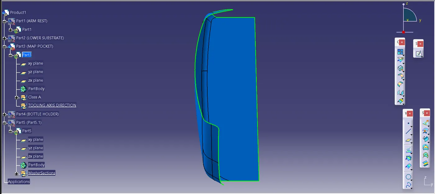
a) In X Direction :
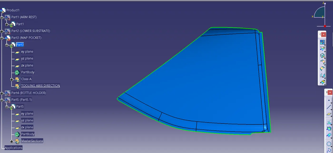
b) In Y Direction :
c) In Z Direction
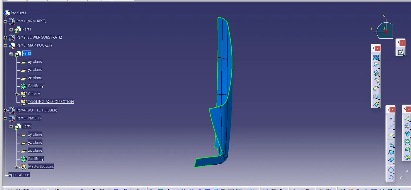
From the above images it is clear that 'Y direction ' is the most suitable direction for creation of Tooling Axis since most of the area is exposed along this direction
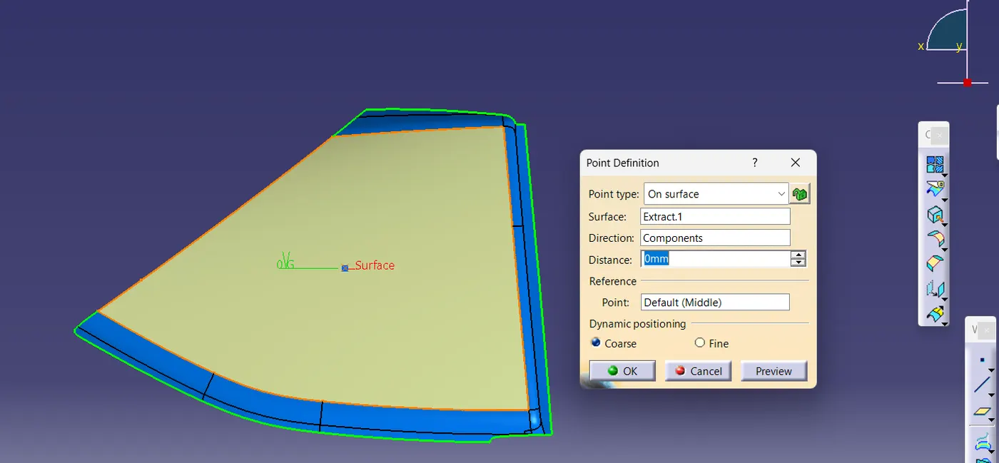
- Create an Extract on surface of Map Pocket as shown and then create a point on that extract
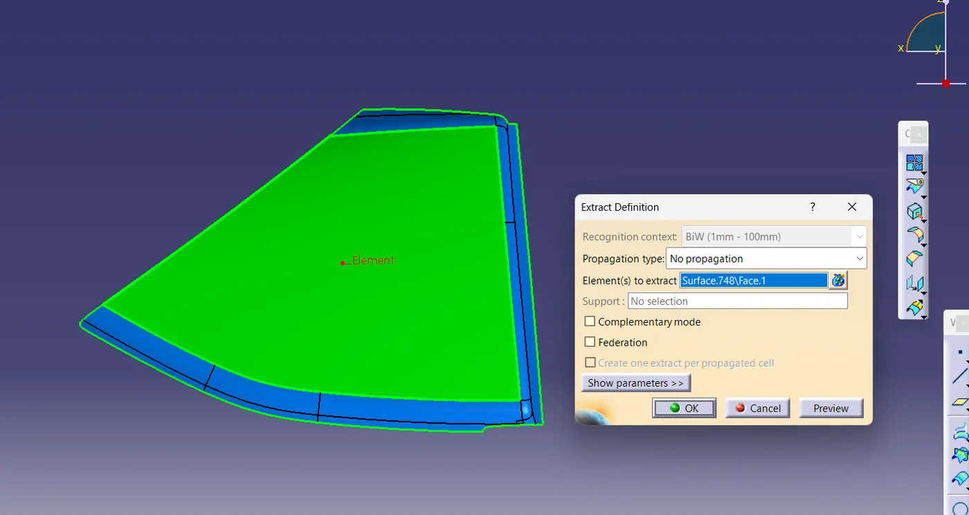
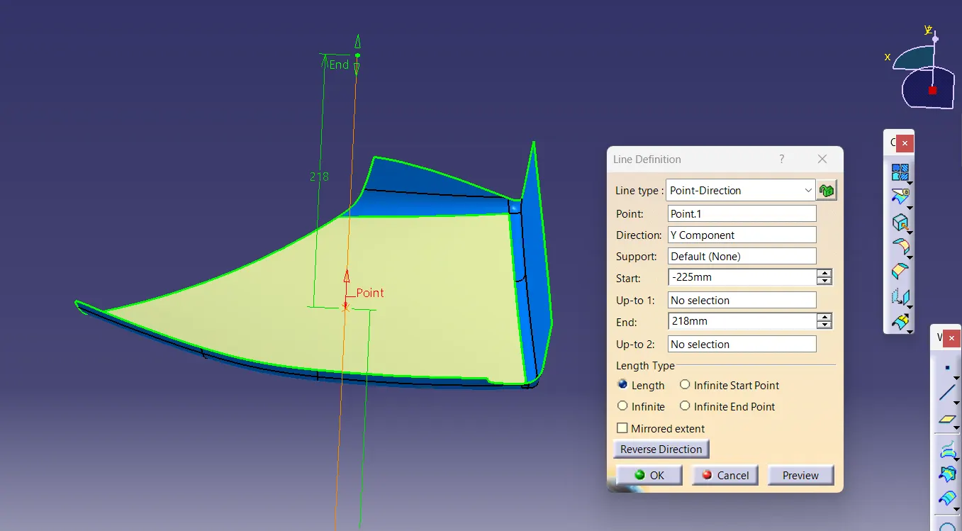
- Now create a Line using Point-Direction method along Y direction as shown
B) LOWER SUBSTRATE
- Similarly ,when viewed from all directions visually, we noticed that here also Y direction is the most suitable direction for creation of Tooling Axis when compared to other axes as most surface area is exposed along this direction
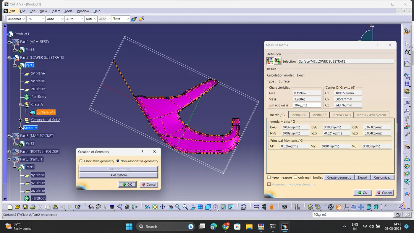
- Create a Point using Measure Inertia command as shown
Go to Measure Inertia command and select the Class A surface then click on Create Geometry where new window is opened up .Then click on Non-Associative geometry and Now select the
Centre of Gravity
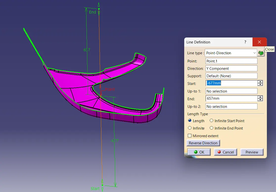
- Now create a line using Point-Direction Method selecting Y direction
C) ARM REST
- First create an Extract on Flat surface of Arm Rest as shown and then create a Point on that extract
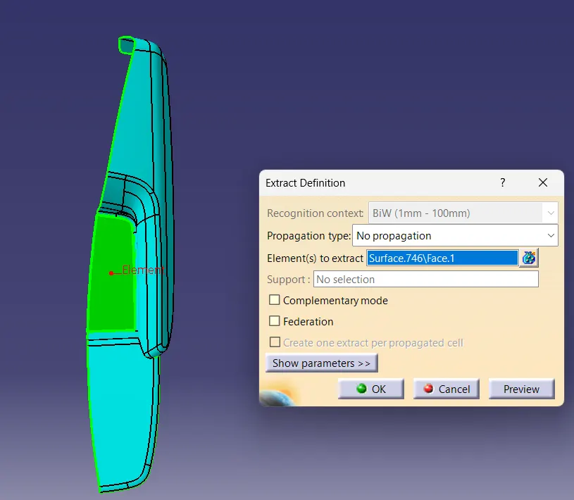
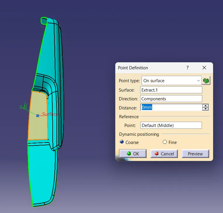
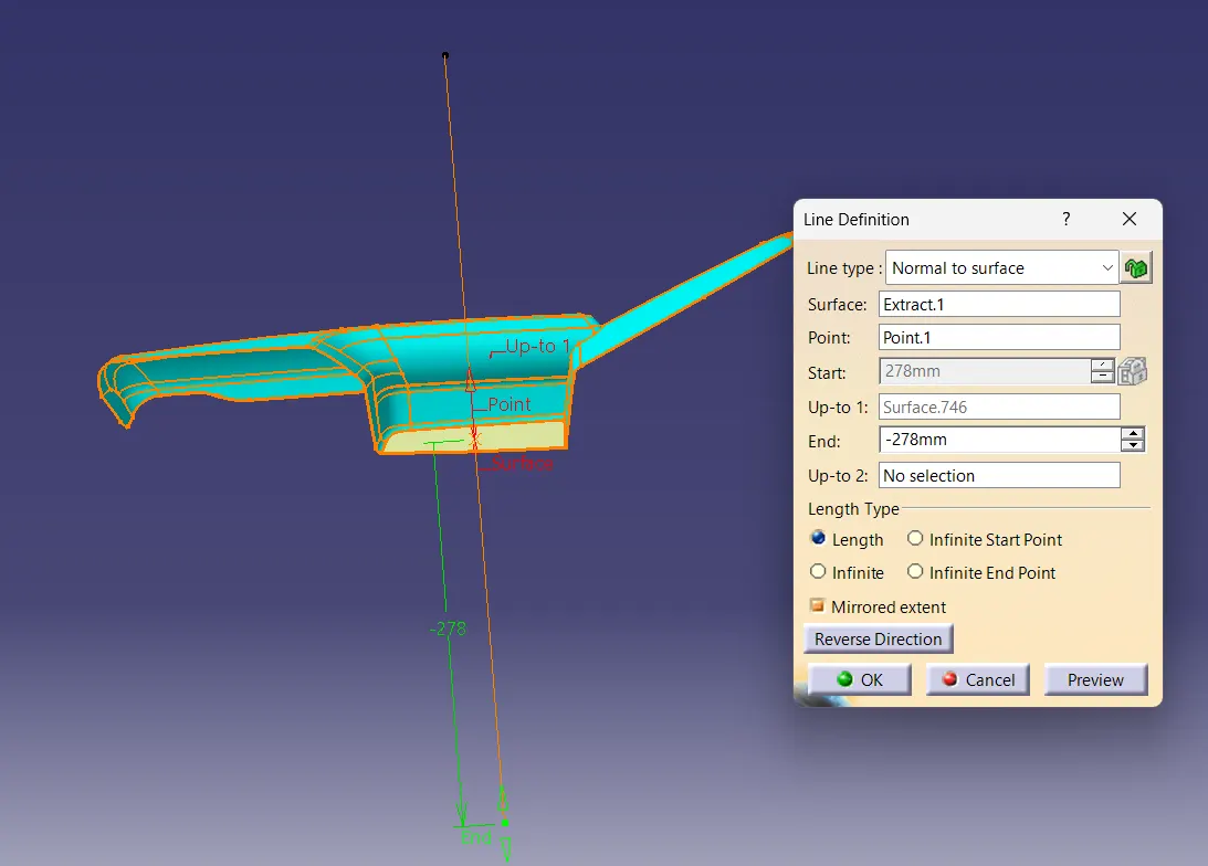
- Create a Line using Normal to surface and point method
D) BOTTLE HOLDER
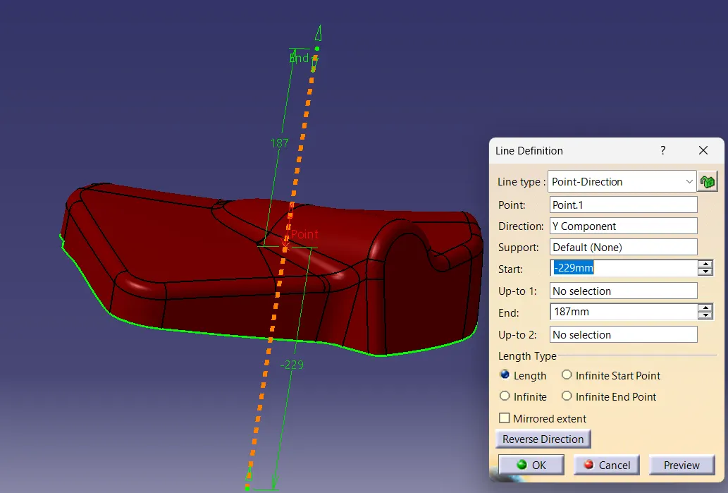
When viewed from all directions visually, we noticed that here also Y direction is the most suitable direction for creation of Tooling Axis when compared to other axes as most surface area is exposed along this direction
- Create a Point using Centre of Gravity and Create a Line along Y direction
2)On ARM REST
- Creation of Flange using Mastersection
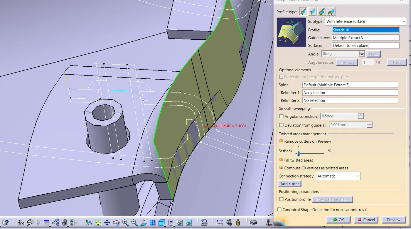
i)First create the plane using three points and then create sketch on the plane .Use " Project 3D elements " on the mastersection whichever you want as the 1st profile .Exit sketch and then take Multi Extract on the Final Trim surface component only (class A+C-B surface) of Arm Rest which will be used as Guide curve for sweep command
)
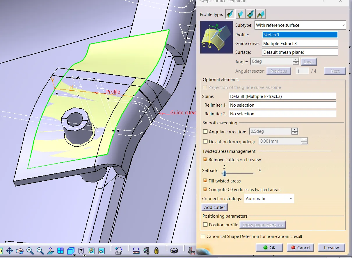
ii)Similarly Again create the sketch ,Now Use " Project 3D elements " on the mastersection whichever you want as the 2nd profile to create surface for Flange using sweep . Make sure that 1st sweep surface and
Flange surface intersects so that atlast we can apply Trim to gest desired output and Later use Edge Fillet of Radius 5.5mm measured from the mastersection.
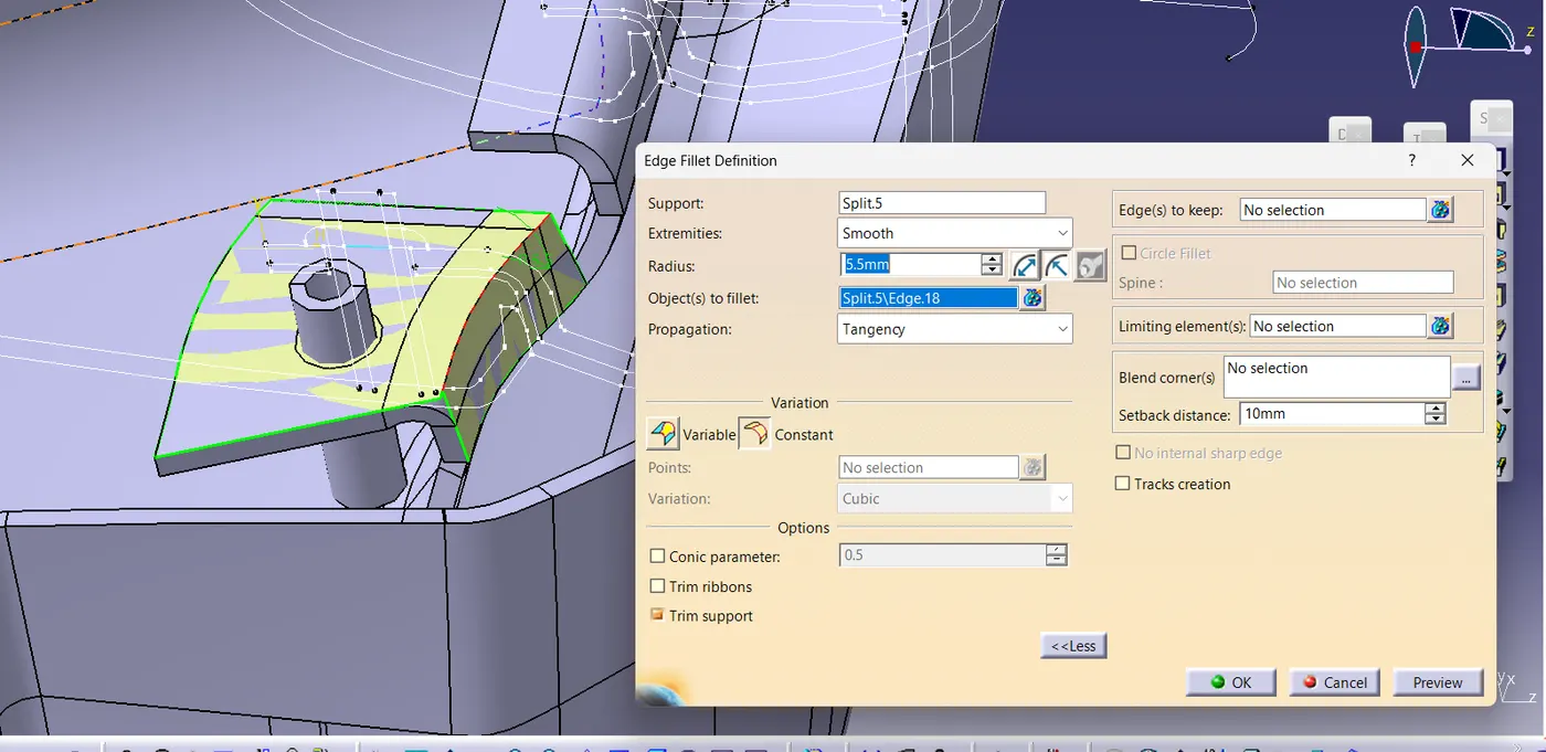
iii)Now Apply Thick Surface of 2.5mm
- Creation of Heat stakes ysing Mastersection
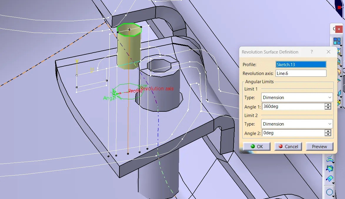
i)From mastersection provided for Heatstakes ,use Project 3D elements by creating sketch on plane created for Flange
ii)Create a Line as Revolution axis for Heatstakes accordingly
iii) use Revolve surface command
iv) use Thick surface fot thickness of 2.5mm
3)On the Bottle Holder
- Creation Of Flanges
i)Create an Extract on Bottle Holder Surface and then create a point on the extaract and Now create a Plane as shown
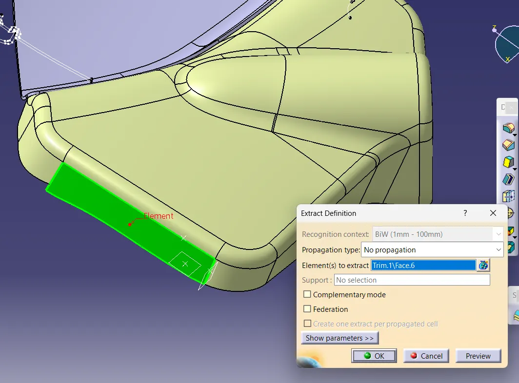
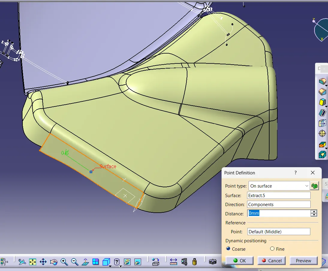
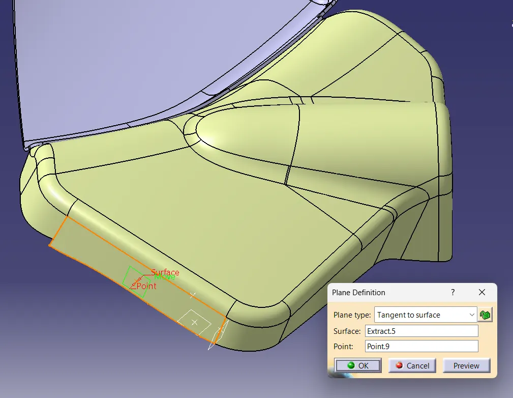
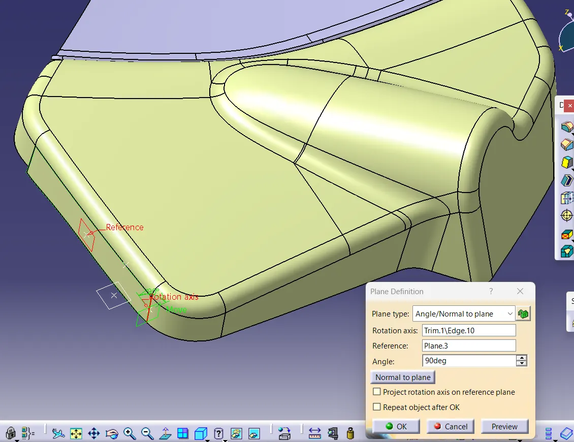
ii) Now create another plane for proper orientation to create the sketch for flange as shown and now create the sketch for Flange as shown .create Multi extract on Final Trim A+C-B surface Component which will be used as Guide curve
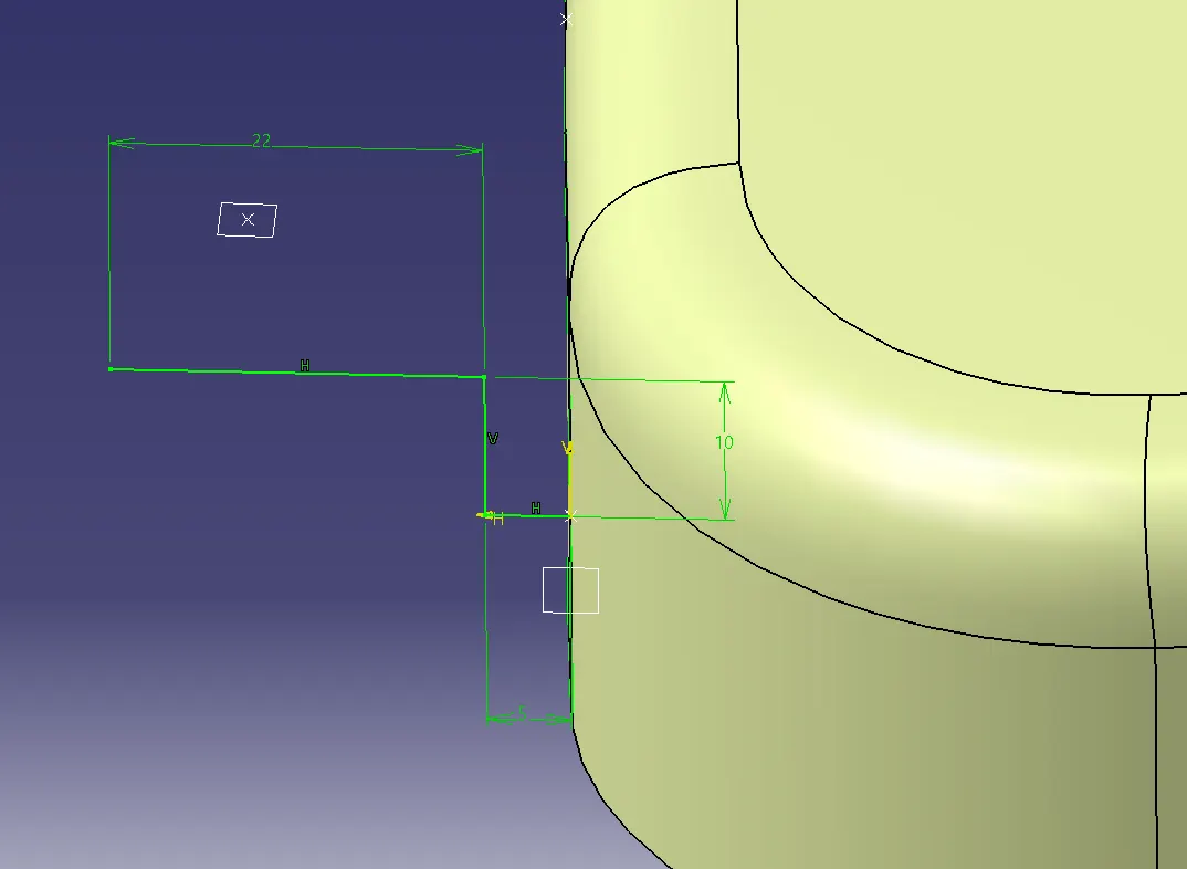
iii)Now use Sweep using Reference surface of 1st type as shown
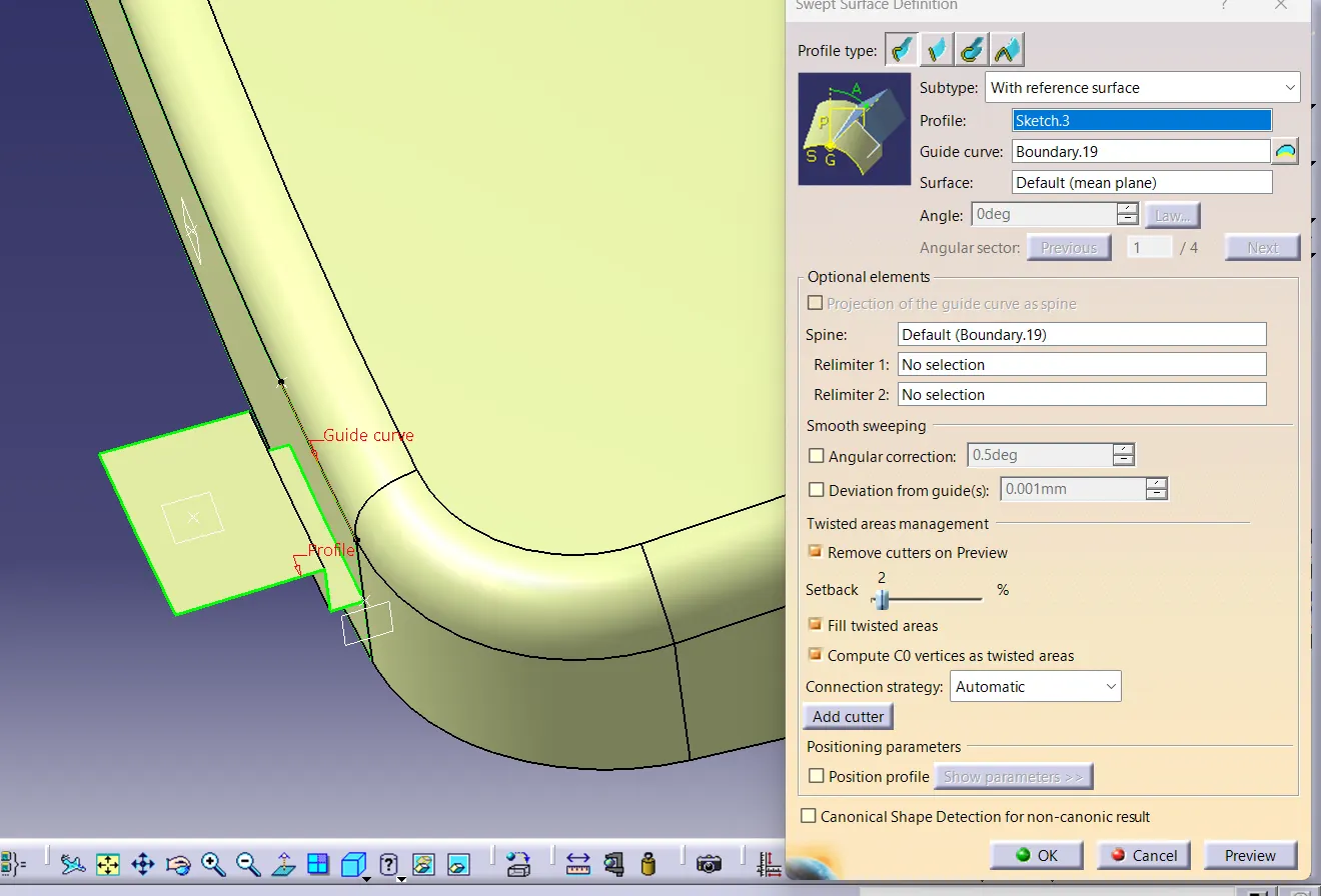
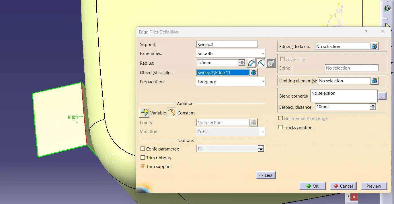
iv)Now provide Edge Fillet of 5.5 mm radius as per the mastersection provided at suitable places
v) Insert Body and use Thick surface by thickness of 2.5mm
- Creation Of Clearance, for Heatstakes on the Lower Substrate rest on the Flange attached to Bottle Holder
i)First Create the Heat stakes on the Flange attached to Bottle Holder, by creating two concentric circles of R2.25mm and R3.75 mm as per the mastersection and then Insert Body .Now use PAD such that it intersects the Lower substrate part and Now use Union Trim .
ii)Now draw another circle of radii 8.5mm on the Flange attached to Bottle Holder . Insert another Body and then Use Pocket Downwards . Define the Flange body (that is attached to Bottle Holder )and use
Remove Boolean Operation to create Clearance .
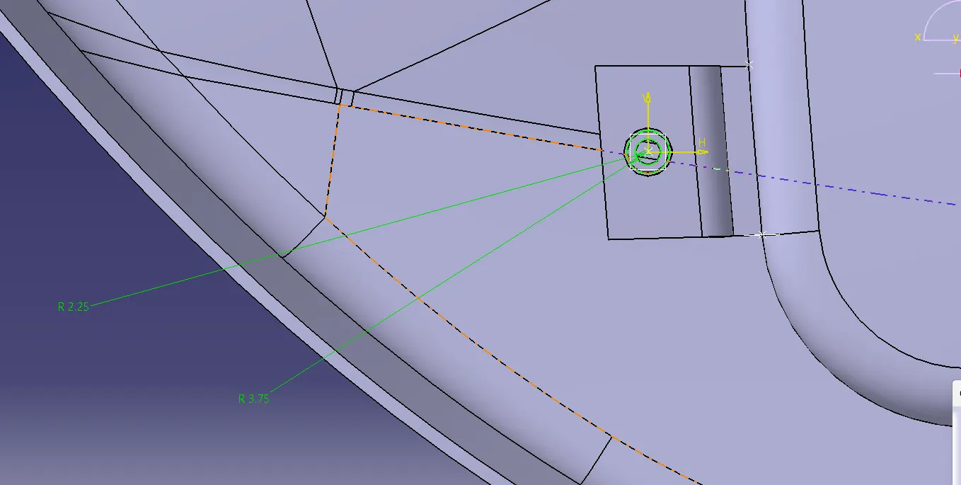
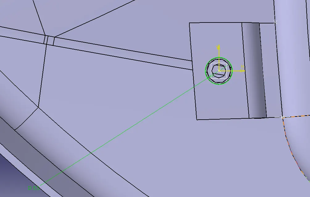
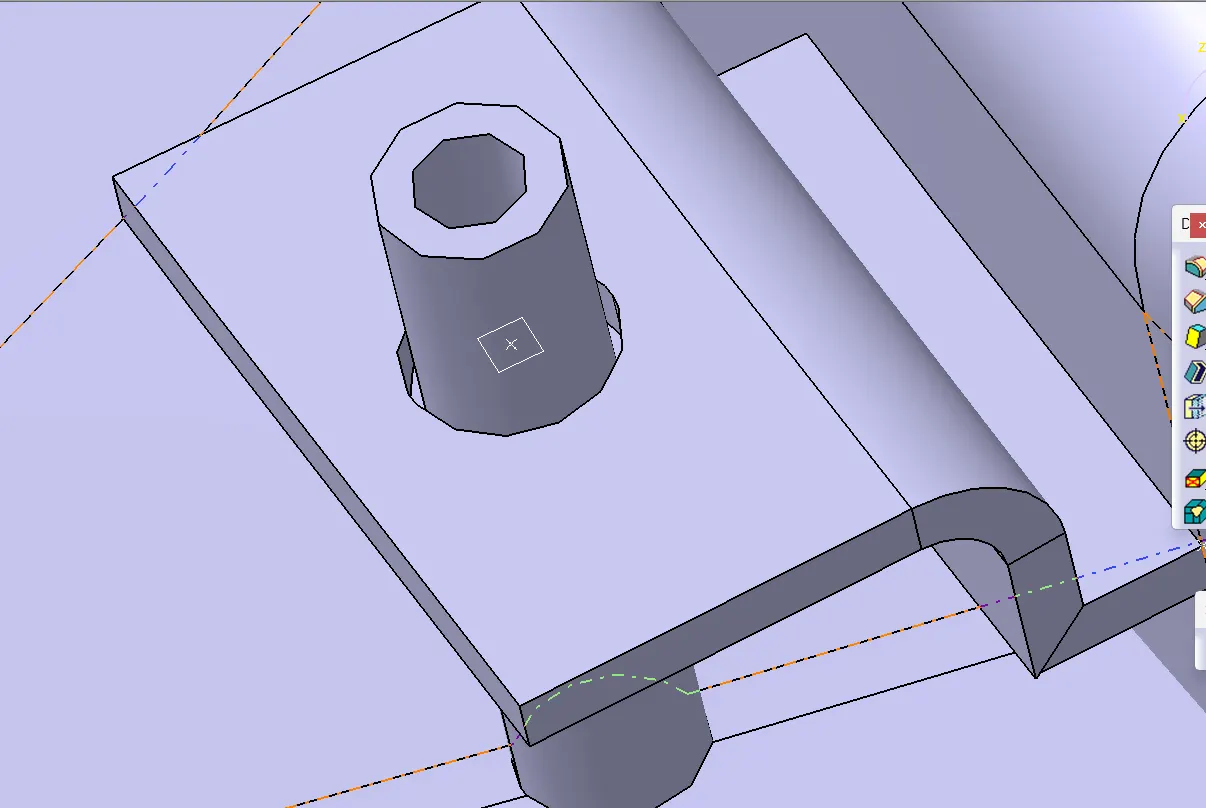
Heat stakes part is saved in Lower substrate part while Flange and clearance are saved in Bottle Holder Part .
Dog House Creation
i) First create Extract and create a point on that extract .Now create a plane using Normal to curve and select Tooling Axis as curve. Now Create a centered Rectangle of 25x25 mmand then PAD it by 25mm up and below to intersect it with the Lower substrate
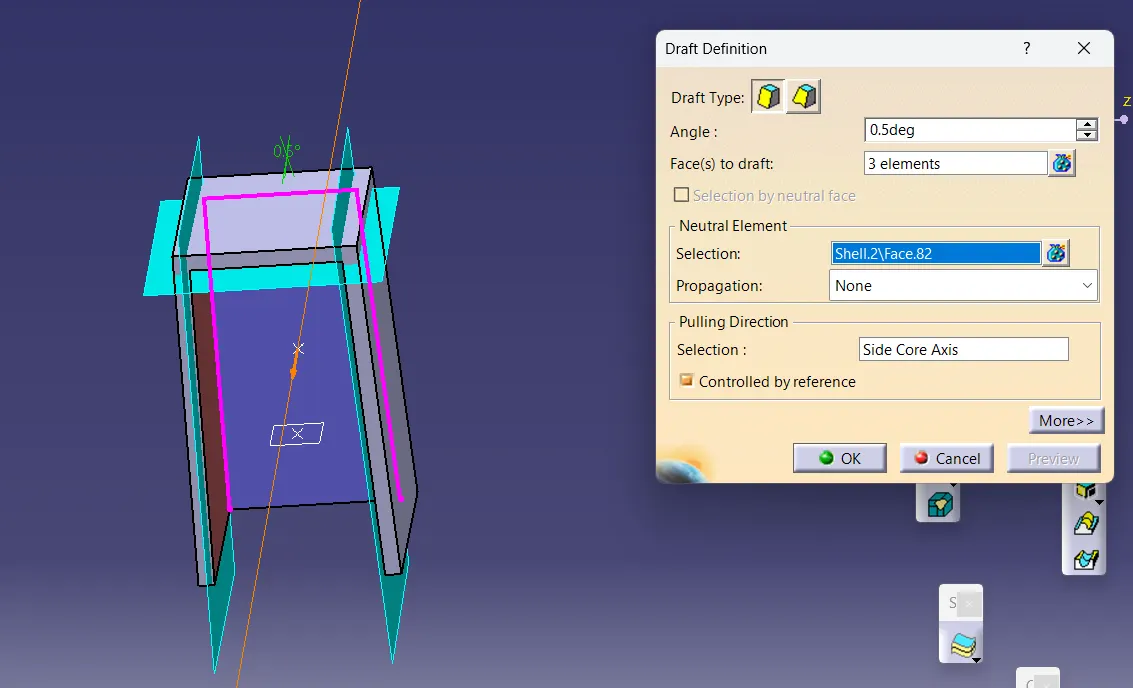
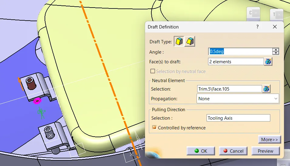
ii) Draft Definition on Outer faces as shown
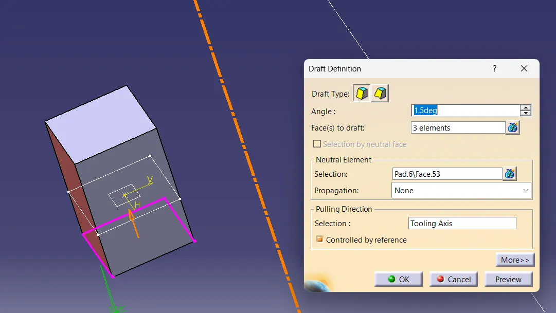
iv) Perform SHELL operation as shown
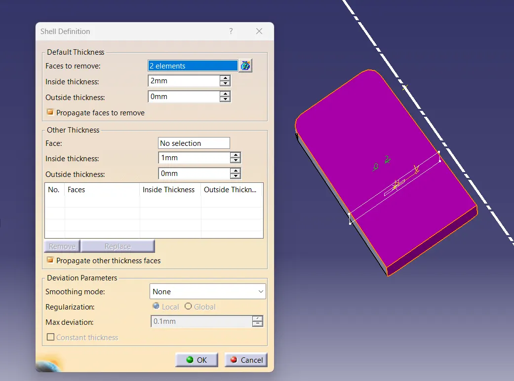
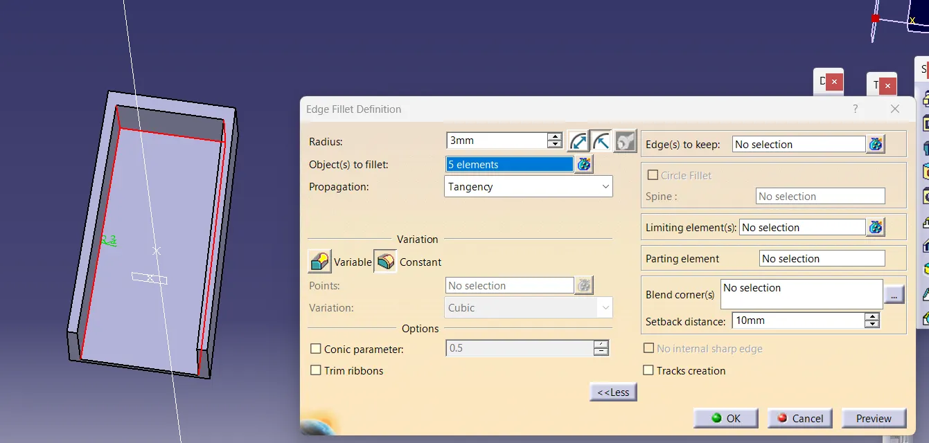
vi)
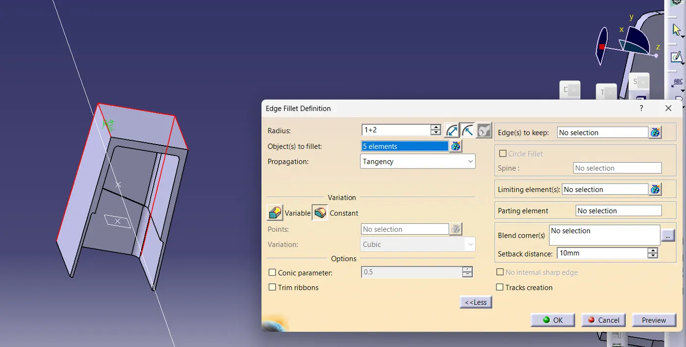
Use Edge Fillet to 1mm only since 3mm is bigger value
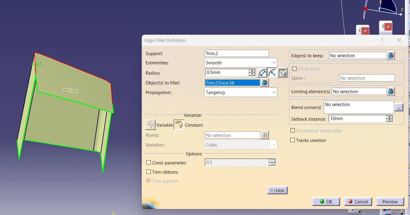
vi) Now Extract inner face of Dog House with Tangent Continuity and Offset it to 1mm( 40% of Dog House Wall Thickness ) . Offset the base surface extract to 3 to 6 mm .
use Trim to get desired output .Now use Edge Fillet of Radius 0.5mm
Vi) use PART BODY Split Command
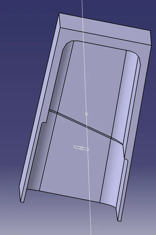
Give EDGE FILLET to Outer edges for 1mm+wall thickness (2mm)
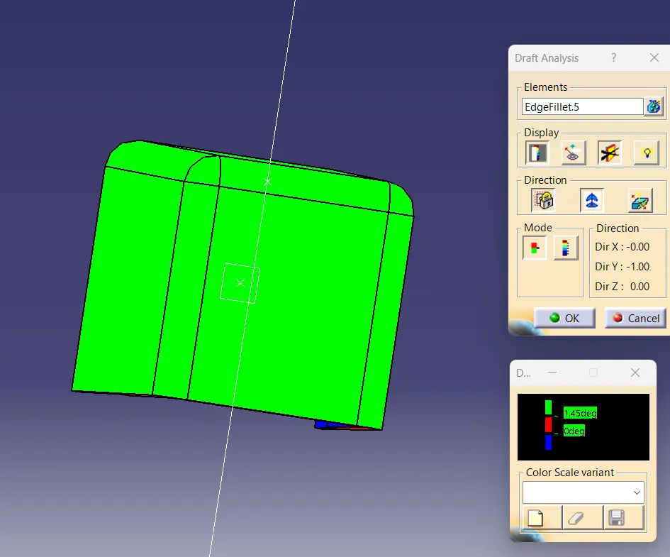
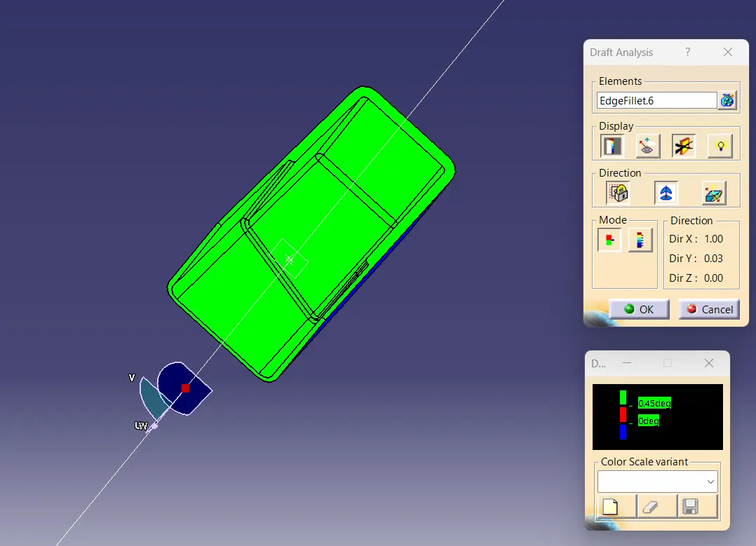
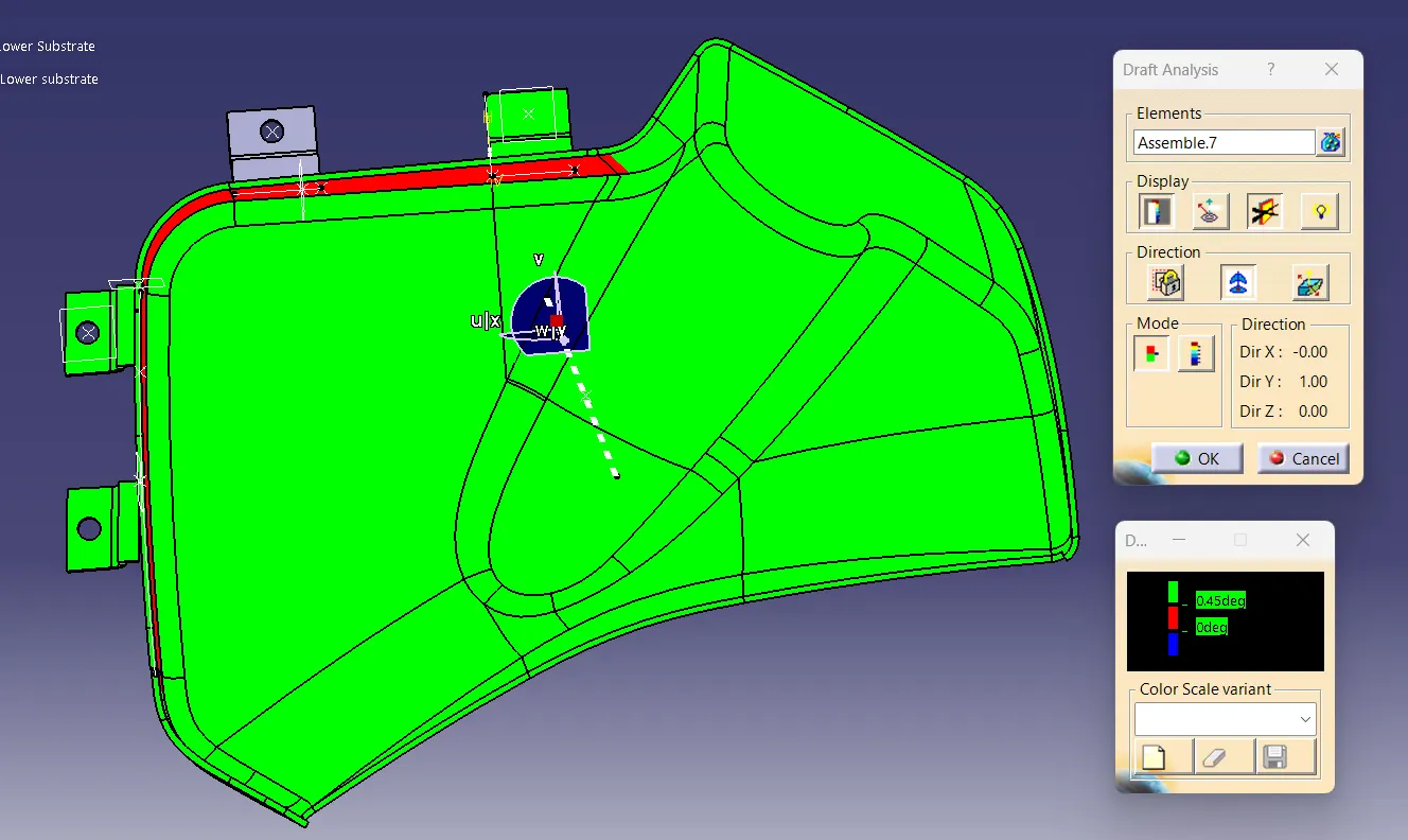
To perform Draft Analysis on Dog House component , Right click the PAD object and then click on Insert in New
a) Draft Analysis on Outer faces
b)Draft Analysis on Inner faces
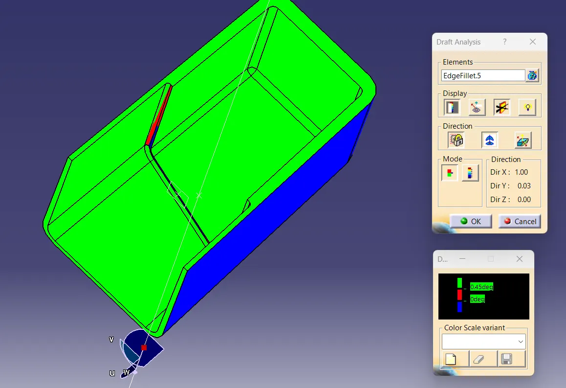
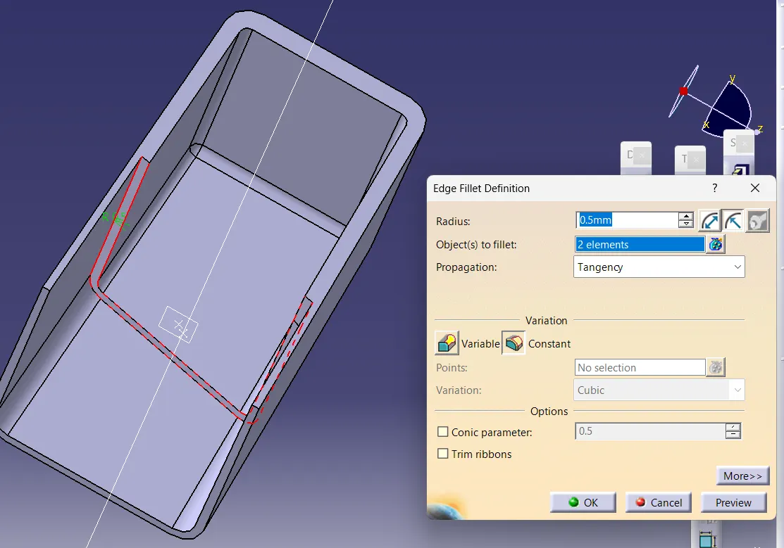
Since Edge Fillet regions are negative draft , delete Edfe fillet region and draft it by 0.5mm accordingly with respect to Side Core Axis
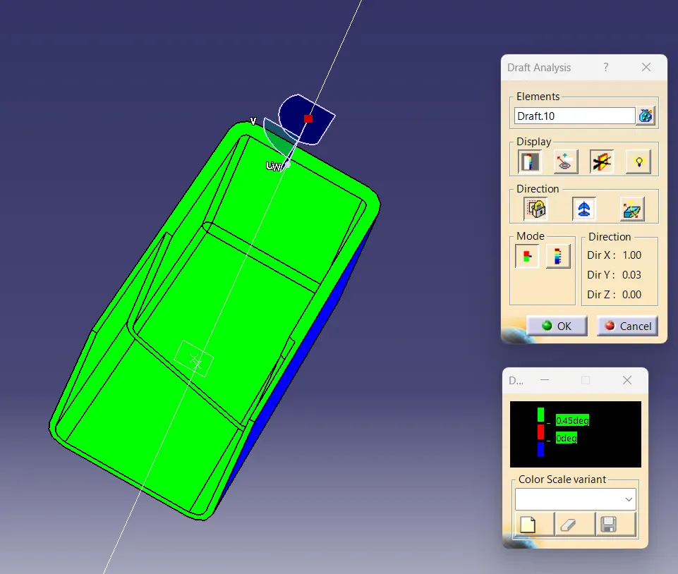
Now again perform Edge Fillet as shown by 0.5mm
Design Of Ribs
4)MAP POCKET
- Creation of Heat stakes
i) create two points using Between up and down on the mastersection provided for Heatstakes on Map Pocket .Now create Line using Point-Point method
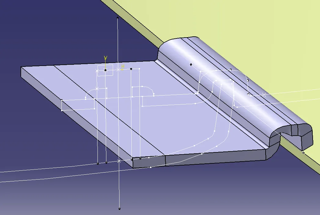
ii) use Revolve command as shown
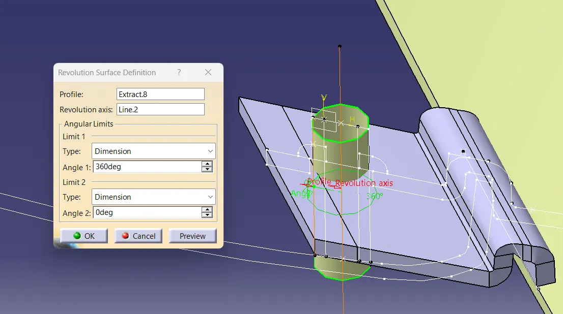
iii) use Thick surface for 1.5mm
iv) Draft it by 0.5 on inner and Outer faces
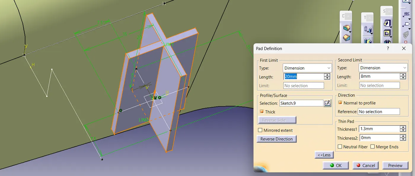
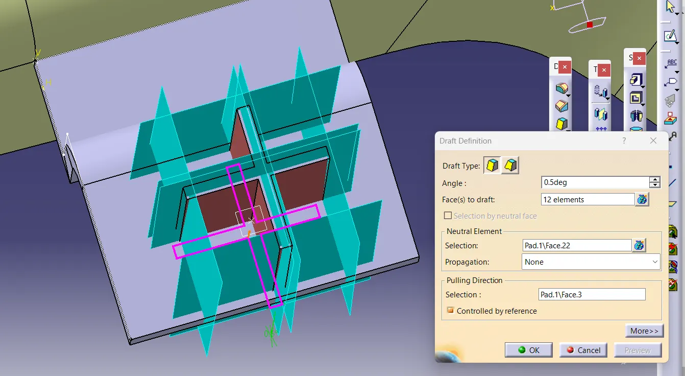
4 Way Locators creation
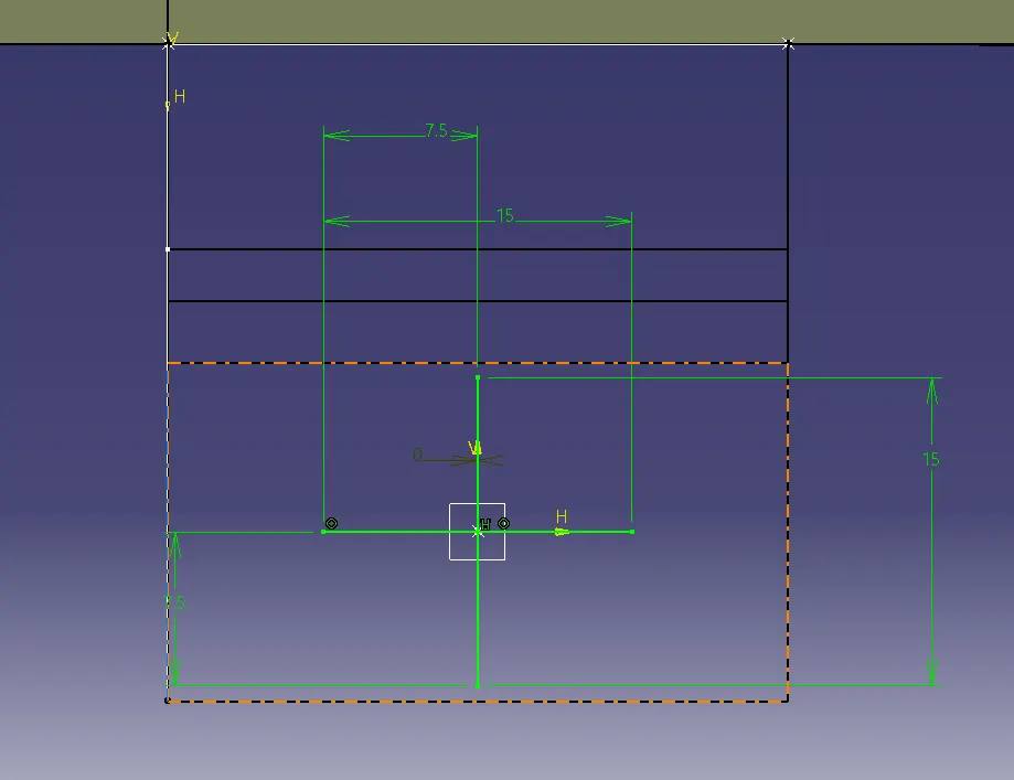
i) Do PAD as shown
ii) EDGE FILLET
iii)CHAMFER
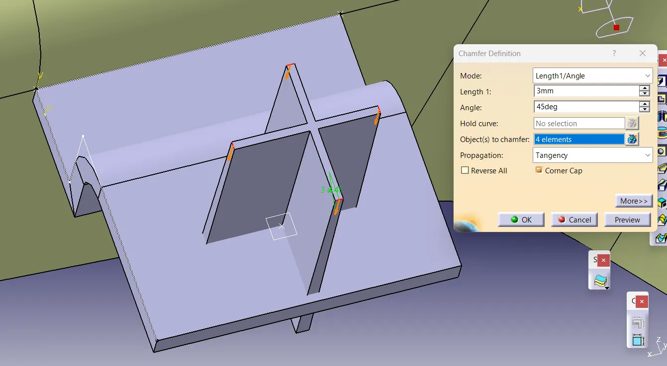
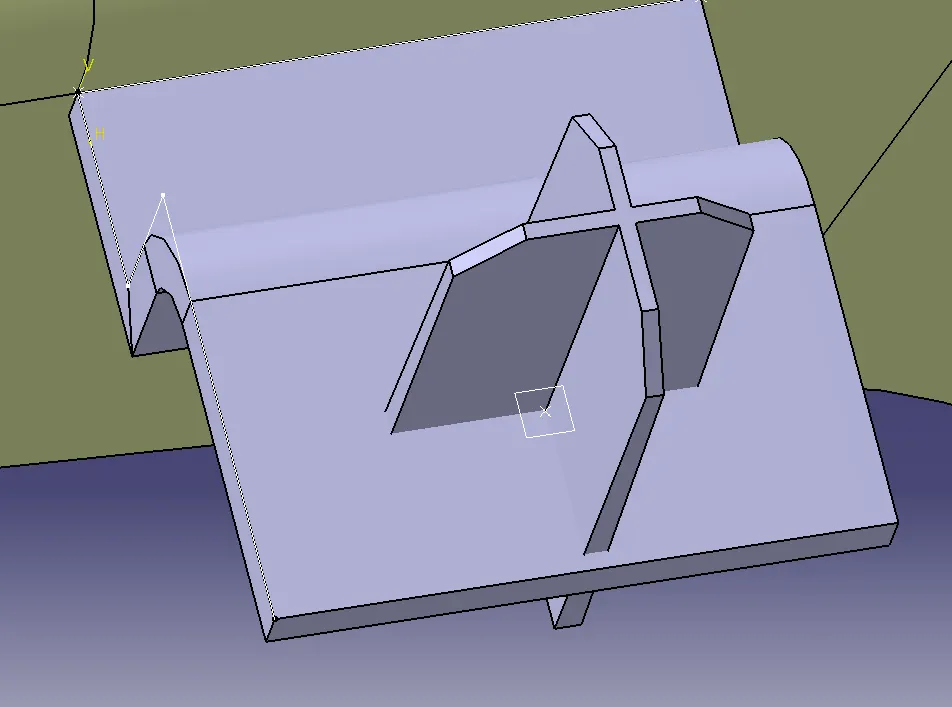
iv) EDGE FILLET
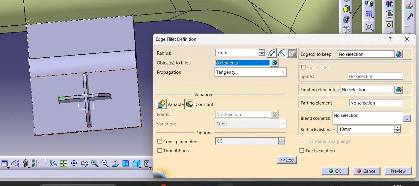
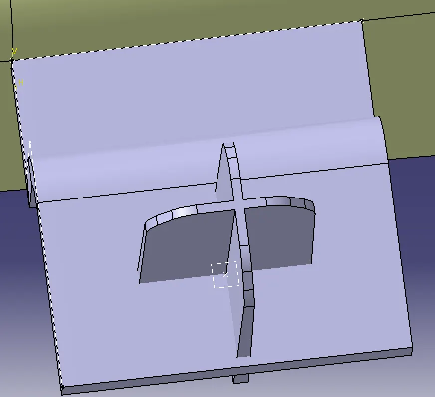
V) Now again perform Edge fillet by 0.3mm as shown
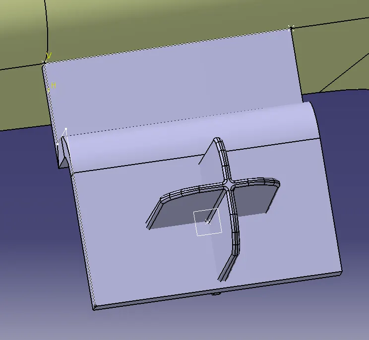
Draft Analysis on Final Assembly components
a)Door Arm Rest
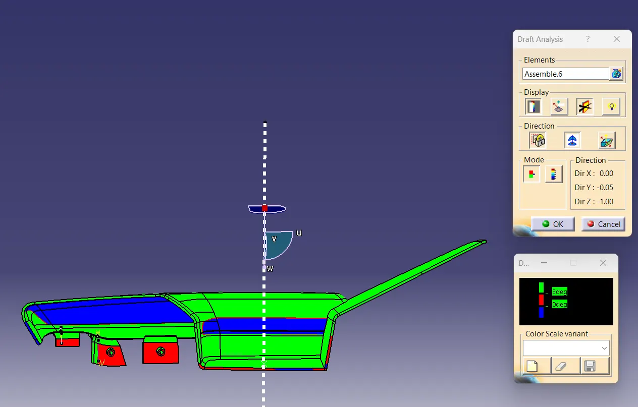
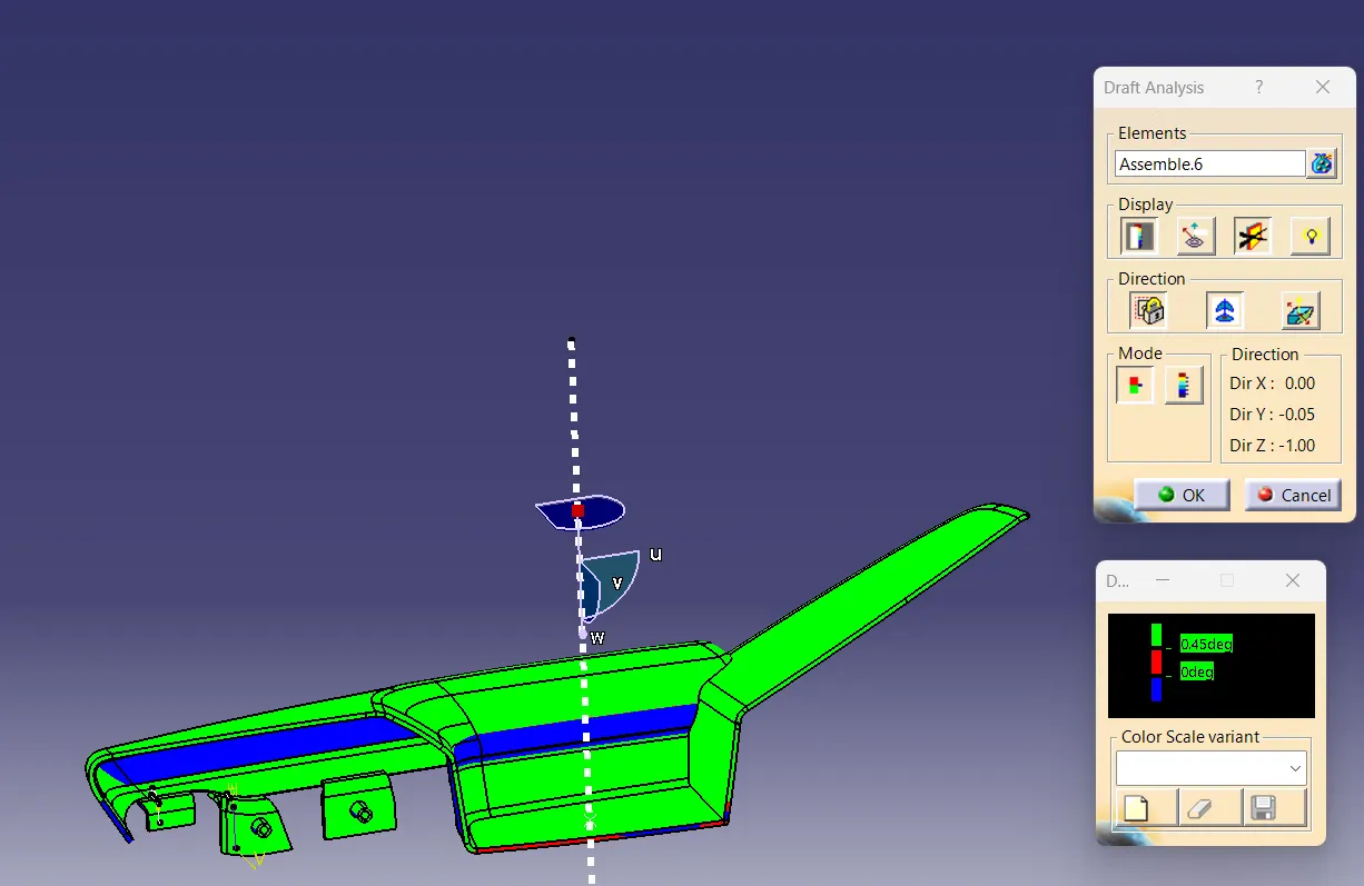
b) Lower substrate
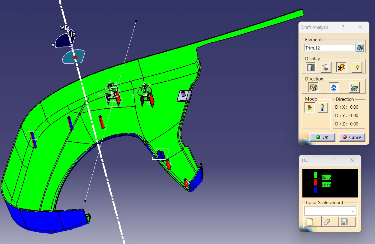
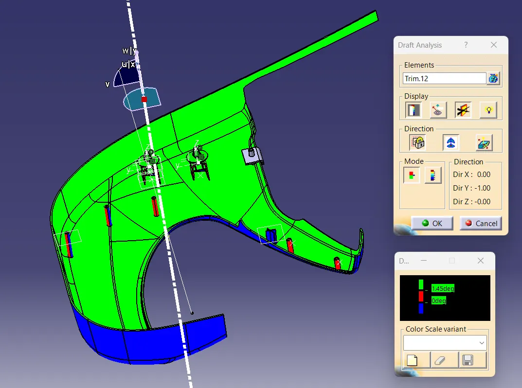
C) MAP POCKET
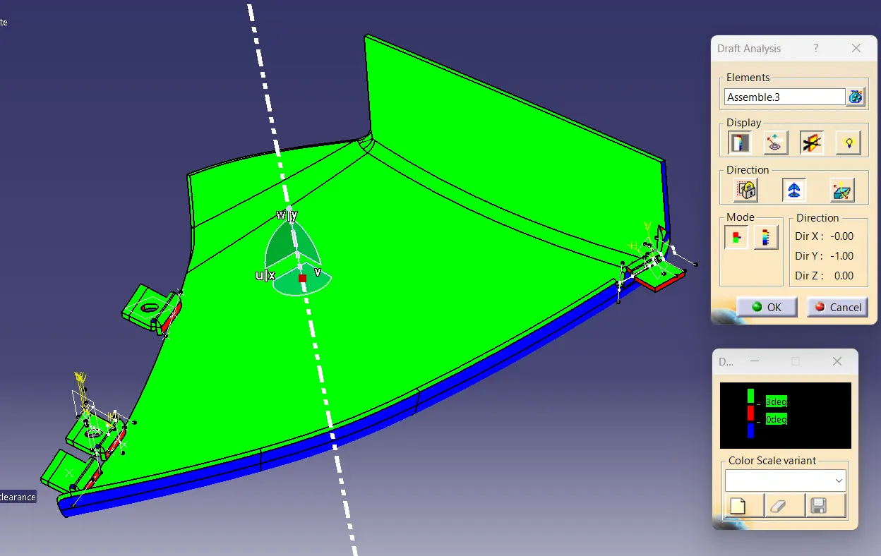
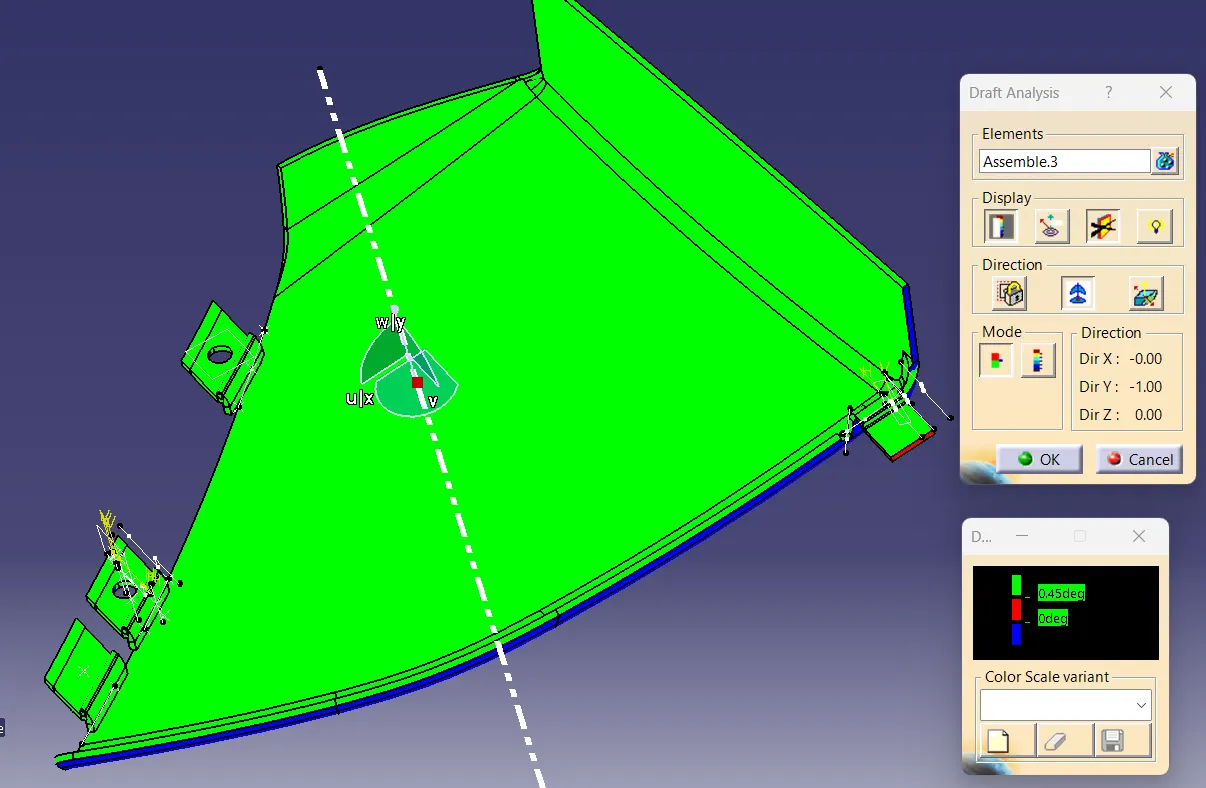
d)Bottle Holder
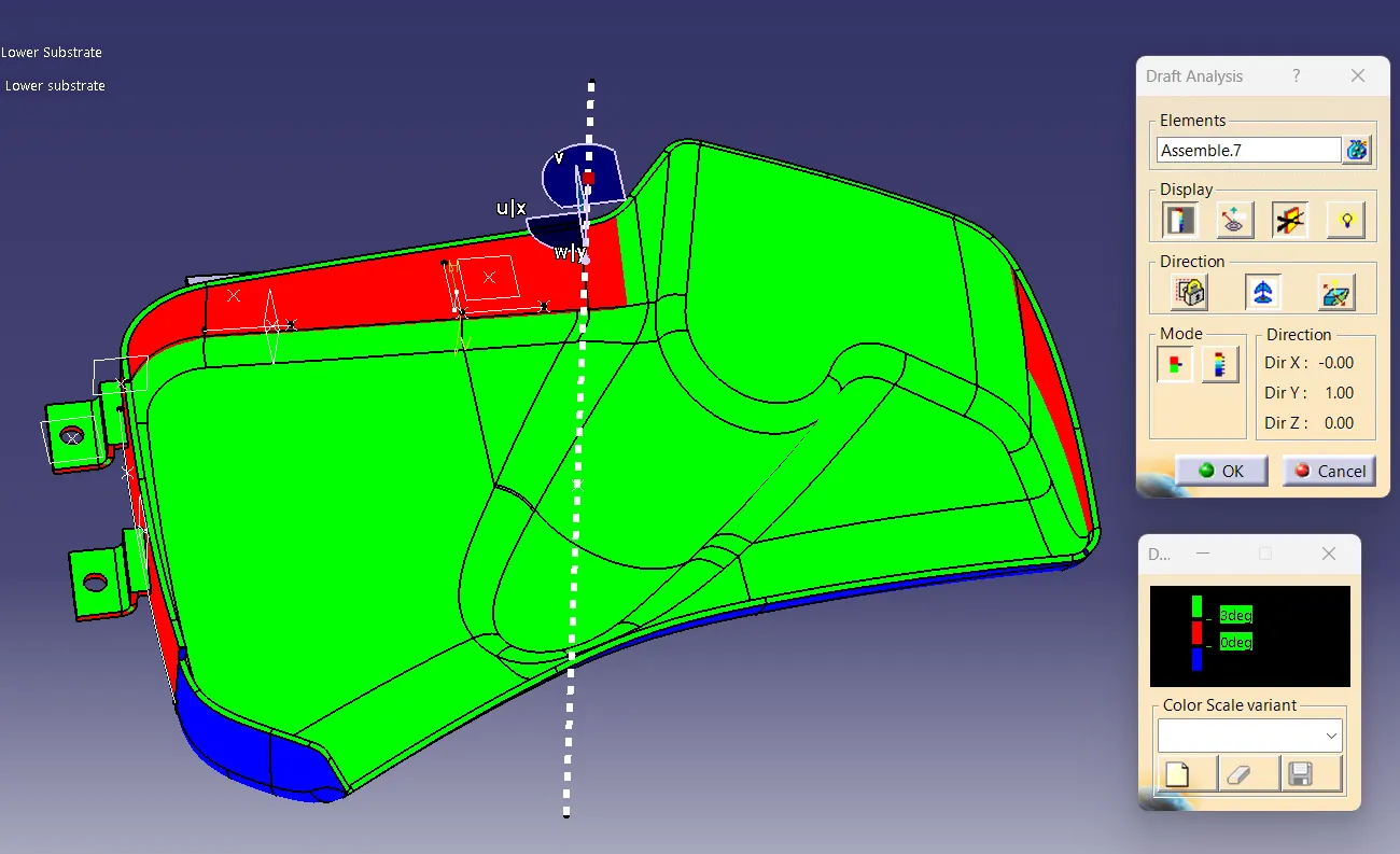
Material Details :
Apply materil Plastic to all components
Creation Of Parting Line :
a)Arm Rest
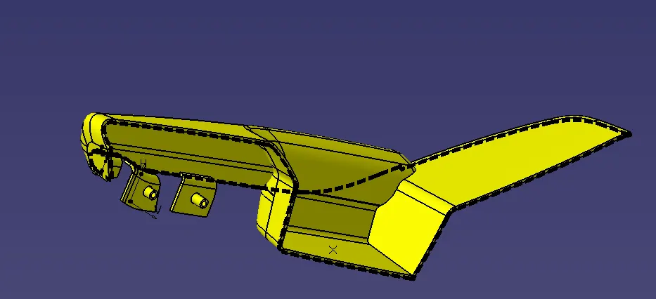
b)Lower substrate
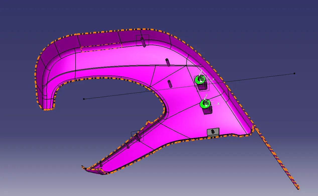
C) MAP POCKET
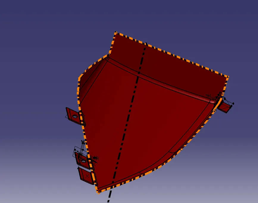
d)Bottle Holder
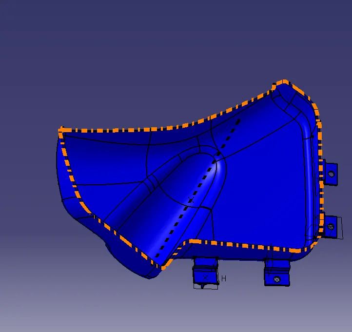
Weight of the Component
- Use " Measure Inertia " command to calculate weight of the component
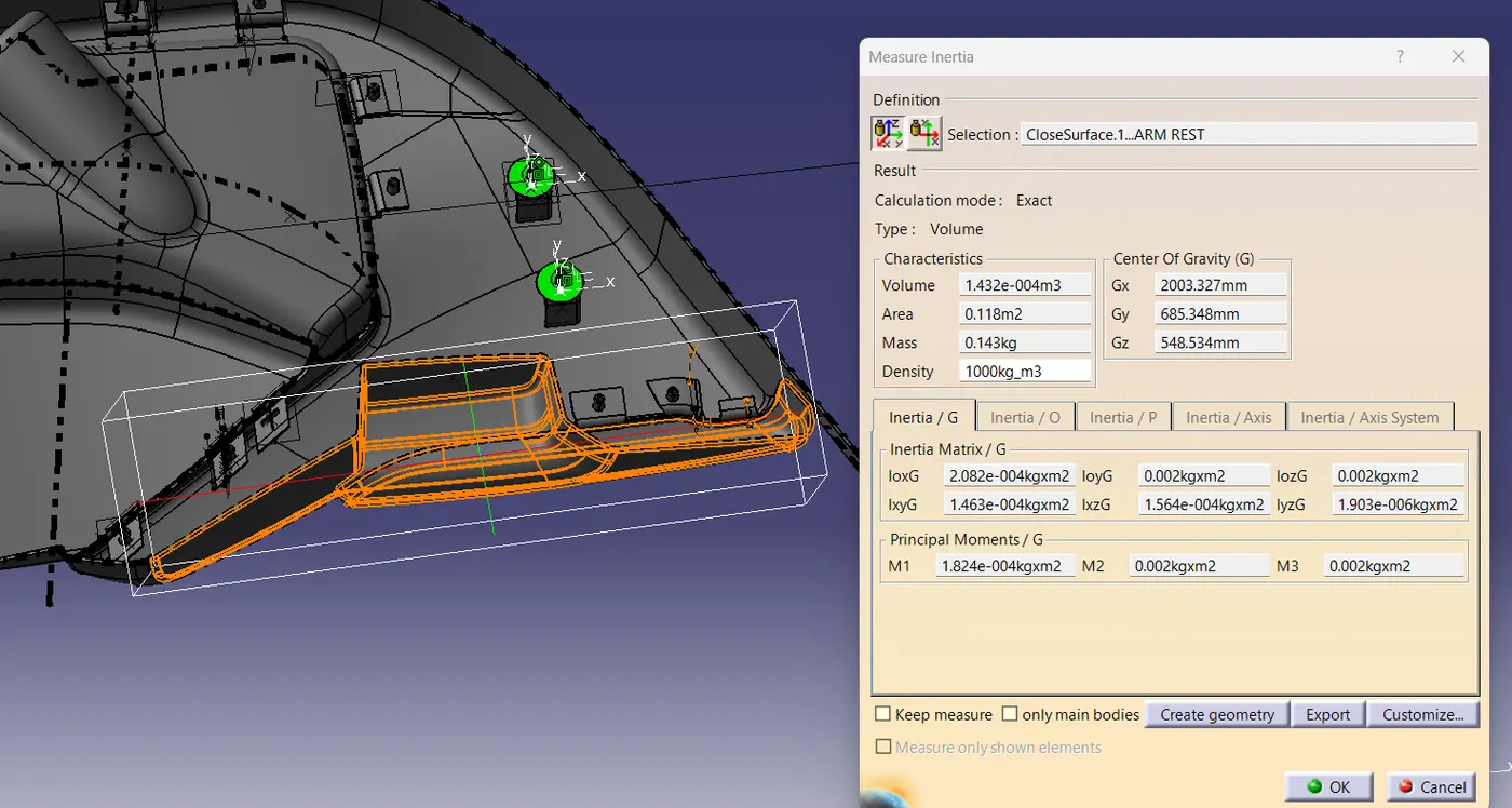
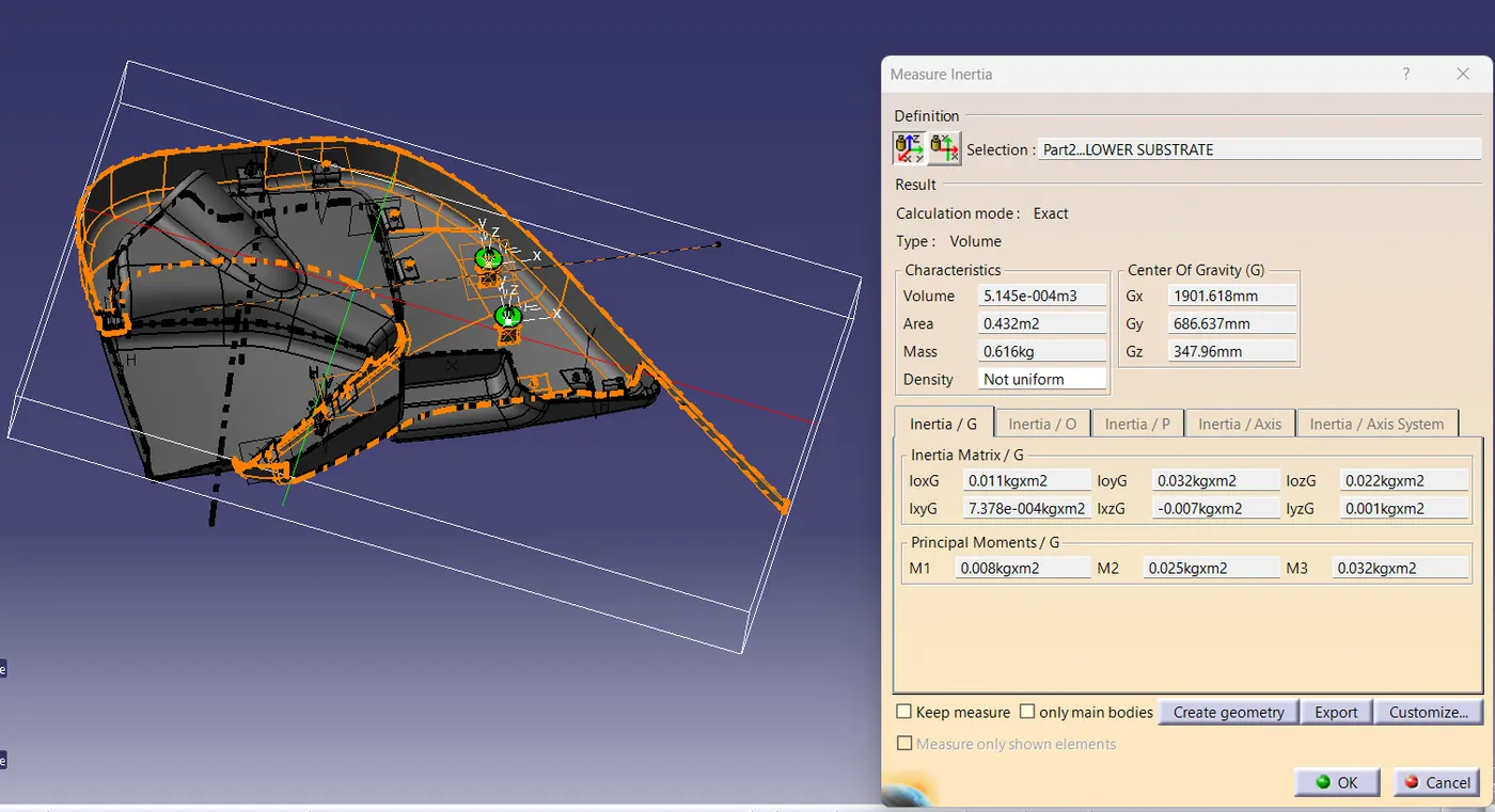
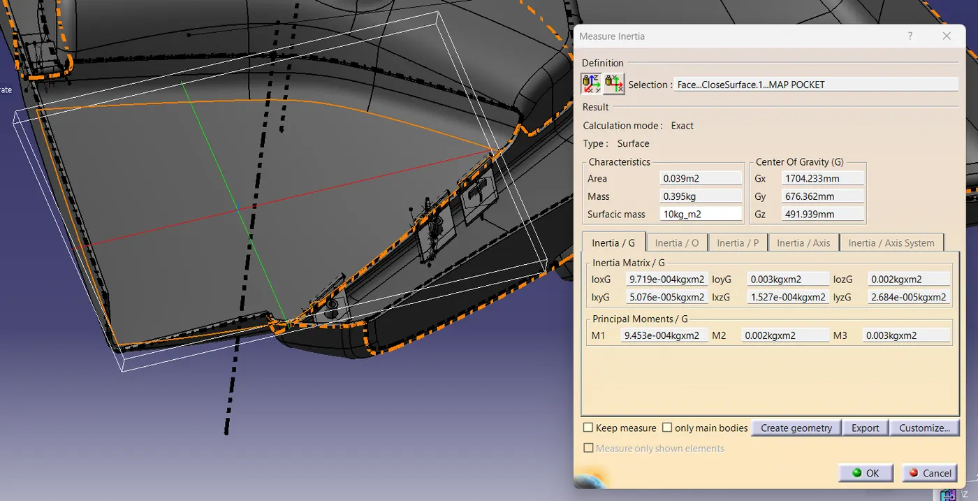
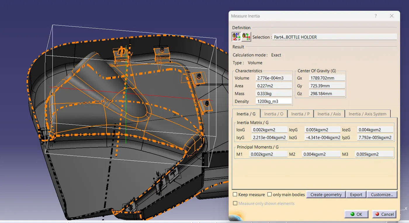
Calculation Of Overall weight of the Product
Arm Rest = 0.143Kg
Lower Substrate = 0.616 Kg
Map Pocket = 0.395Kg
Bottle Holder = 0.333Kg
The Total Weight of the product = 1.787Kg