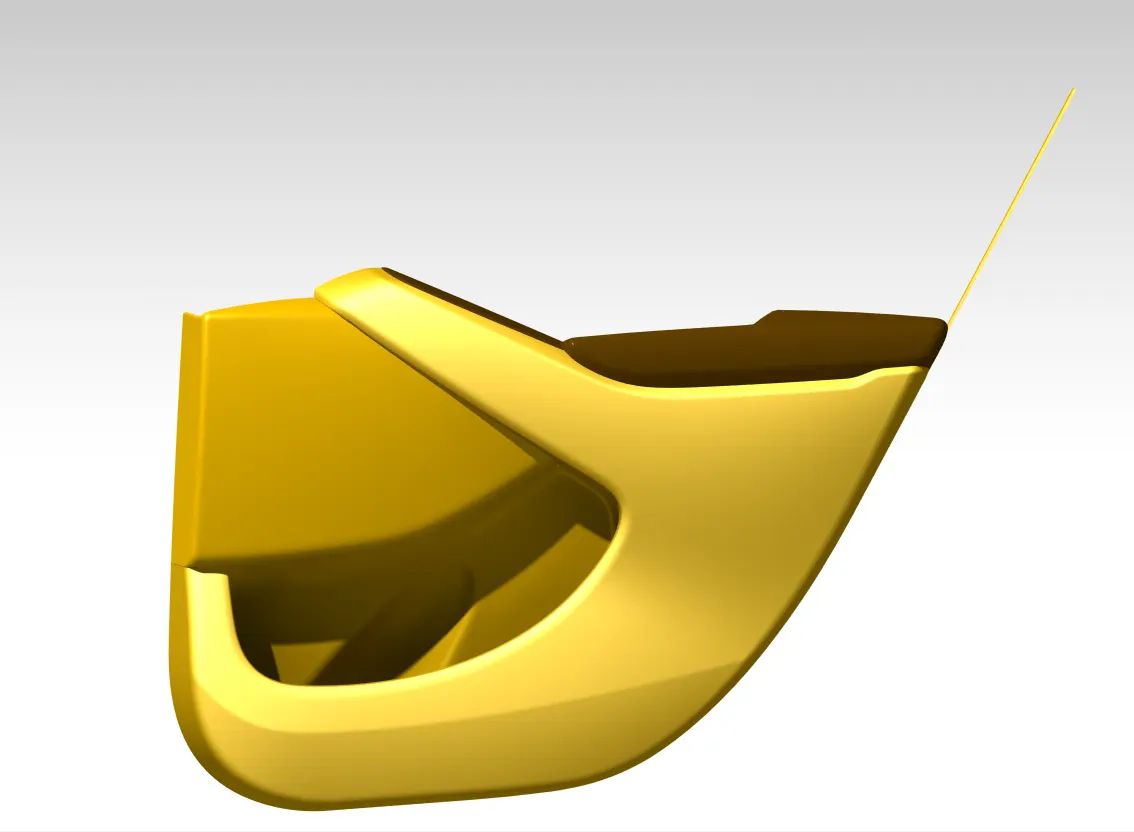
Week 12- Final project
Problem Statement - Plastic Design of a Door Trim panel
- Creating thickened parts using the master section for reference.
- Creating the mounting features as per design guidelines in the industry and with master sections.
- Applying material details
- Draft analysis & Tooling analysis
- Creation of parting lines and checking tooling feasibility.
Solution -
The following Door Trim components are to be designed -
- Lower Substrate
- Bottle Holder
- Applique
- Arm Rest
Let's start with Lower Substrate since all other components will be mounted with it.
1. Lower Substrate
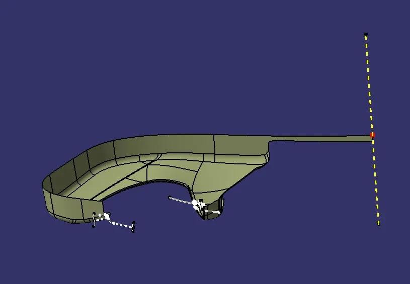
Creating Tooling Axis- While creating the tool axis make sure to check with all draft surfaces and use the "bisection method" to create a mean line for the tooling axis. A draft of 3-deg is recommended for all surfaces.
Draft Analysis- Perform a draft analysis along the created tooling axis. If the surfaces pass the 3-deg criteria then we can move forward else co-ordinate with the styling team and get things rectify.
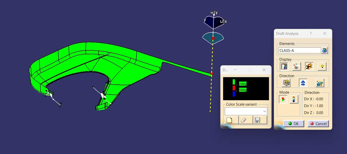
Since our part passes the draft criteria so we can move forward with creating Class-B Surface.
Creating Class-B- For creating Class-B for complex surfaces we first try to offset all surfaces as per given thickness. If achieved we are good to move on next step else offset all non-erroneous surfaces and extrapolate individual surfaces and trim them and then give the necessary fillet. This process of converting non-parametric to parametric is called remastering of the surface.
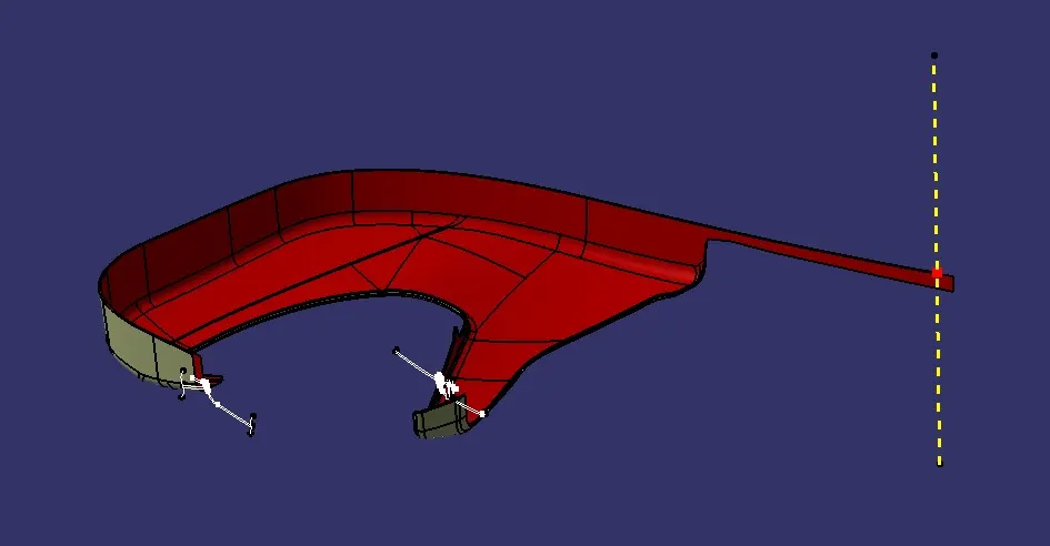
Class-C Surface- For the surfaces parallel to the tooling axis use "swept with reference surface" and give a 90-deg angle. Also, for surfaces perpendicular to the tooling axis "sweep with draft direction" will be used with 3-deg of draft angle in the outward direction. Create all the surfaces, extrapolate them, and trim them to form a single surface.
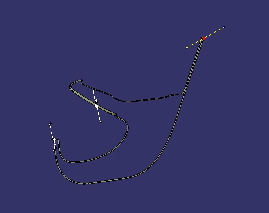
Closed Surface- Use Join Command to join Class-A & Class-C surfaces. Now use the trim command to form a closed surface. If all boundaries are not extending then extrapolate the boundary. Use Boundary Command to check whether the body is closed or not. Finally, use the Close Surface command to make the solid part. Apply the material.
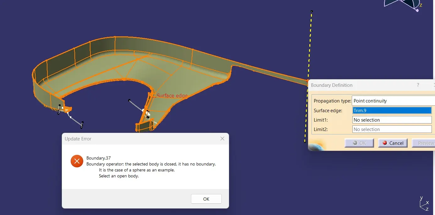
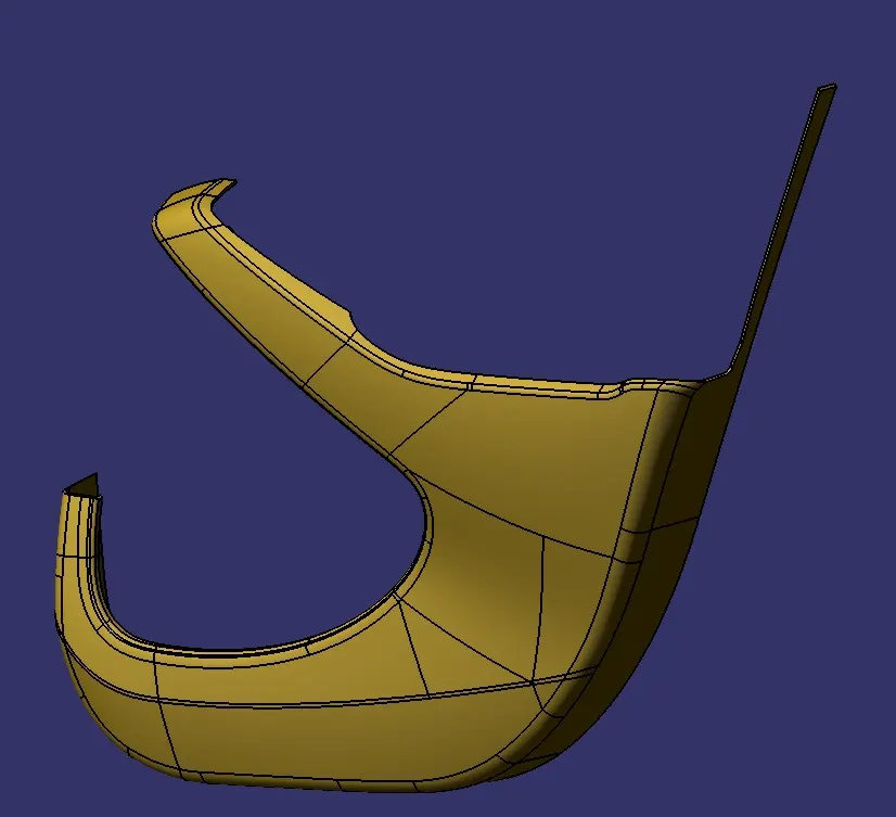
Similarly, create Close Surfaces & Solid parts for other components.
2. Bottle Holder
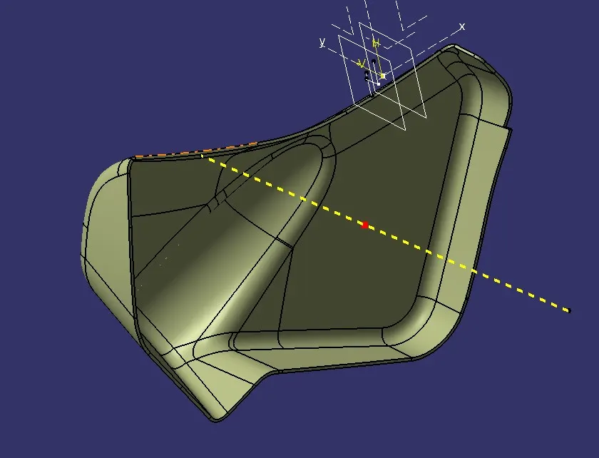
3. Applique
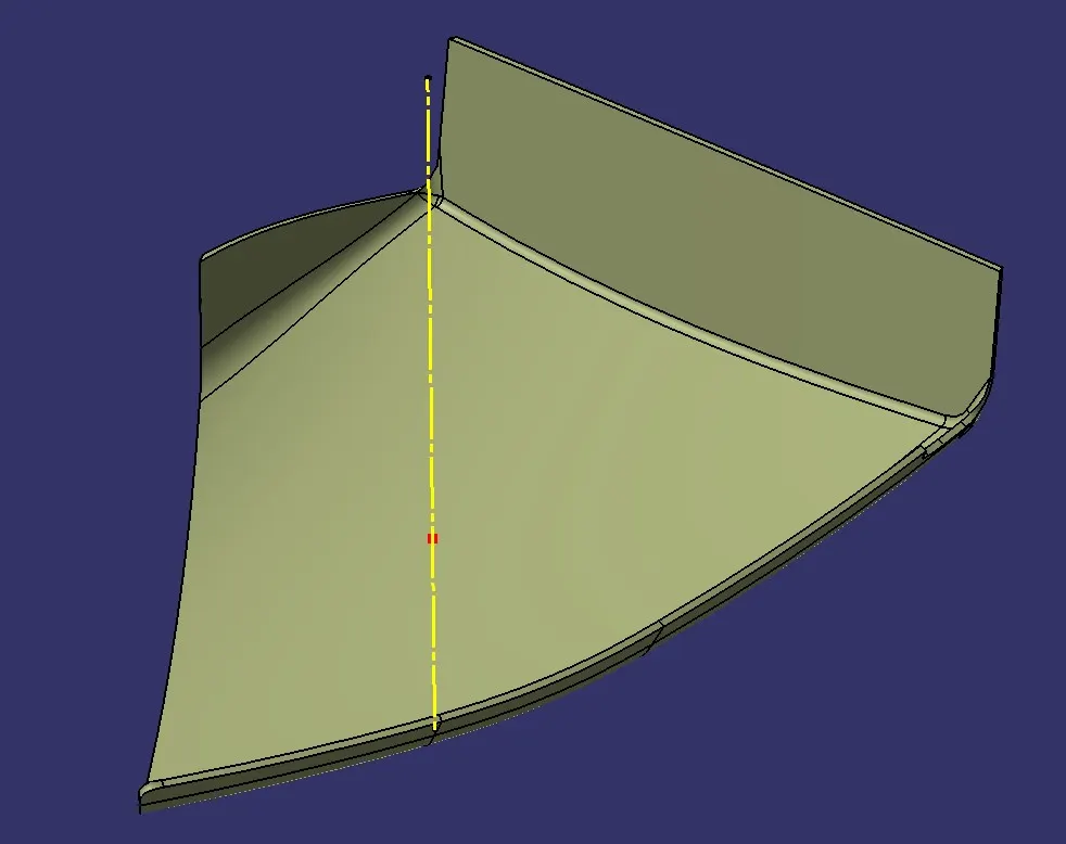
4. Arm Rest - It will have 2 tooling axis one for the side core.
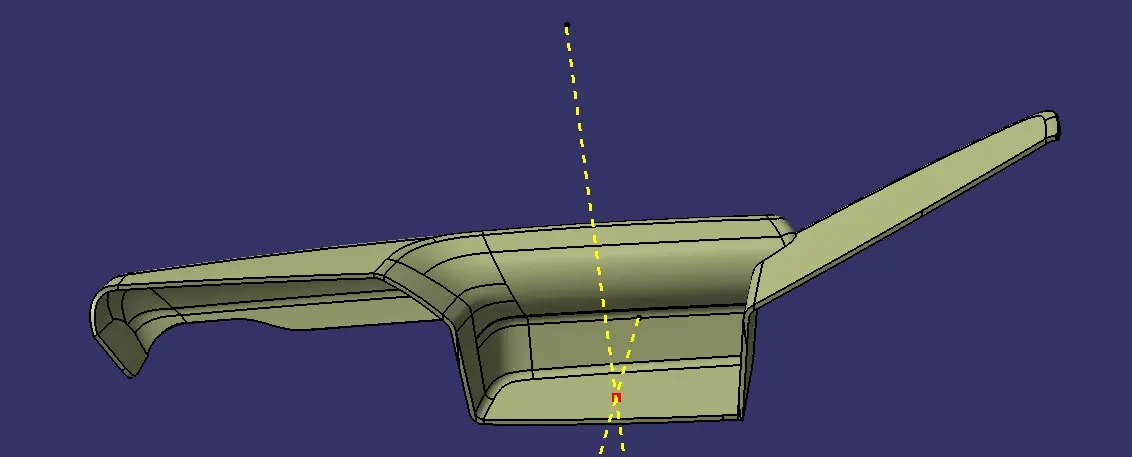
Fixation Strategy -
Heat Stakes- It is an engineering feature used to permanently assemble parts using the plastic welding method. Design consideration for Heat Stake -
- Inner Dia. - 4.5-5mm
- Outer Dia. - 7-7.5mm
- Stake Height < 5x>
- Draft - 0.5-deg
- Stake Ribs - They should sit on the flange created for assembly.
- Gap b/w stakes - 50-60mm
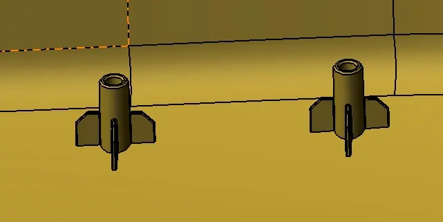
Ribs- Ribs are used to provide strength to the part without increasing the part's overall thickness. Design Consideration-
- Draft - 0.5-deg
- Tip Thickness > 0.75mm
- Height < 5x>
- Gap - Least 2x(material thickness)
2/4-Way Locator- Locators are used to constrain the motion of part w.r.t other part. A 2-way locator restricts 2 DOF & 4-way restricts 4 DOF. The height of the locator should be greater than the height of the heat stakes for proper alignment of parts. Chamfer is provided at the tip of a locator to ease assembly.
Dog-House - They are used to provide the necessary height for other B-set features. The bottom section has to core out such that it has less than 60% of material thickness up to a height of 3-6mm. An extra side/lifter core is required for clearing the inner side of the dog house. A draft of 1.5-deg is required for the dog house.
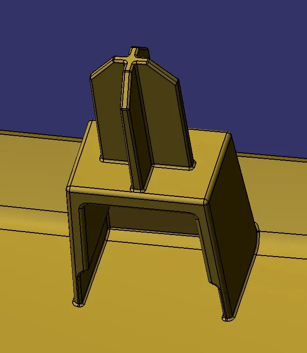
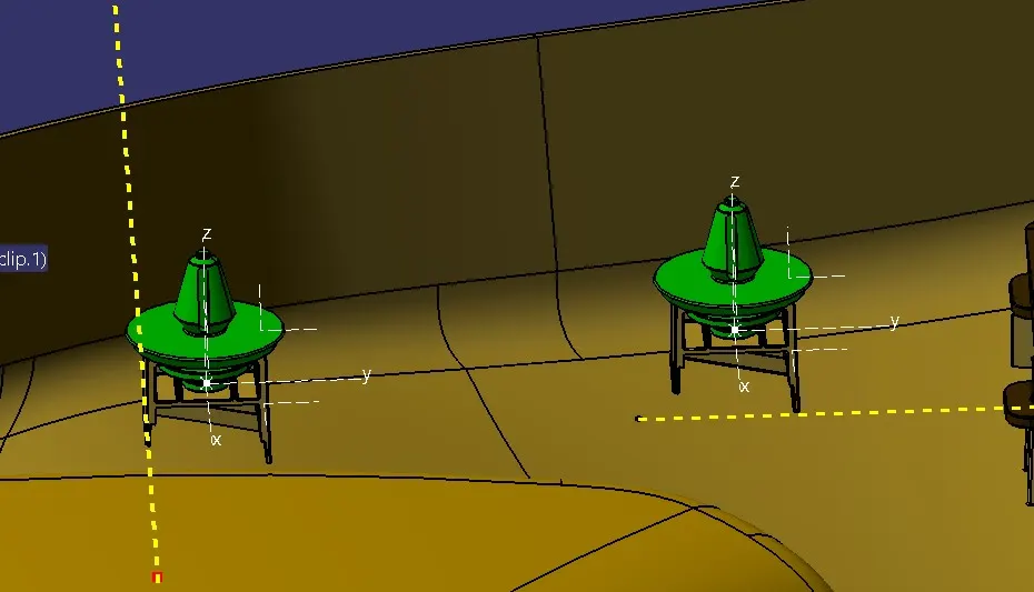
Push Pins - Push Pins are used for attaching the Plastic body to the BiW body of the Door. Dog House with the slot on top is used to assemble a push pin with a plastic body.
Flanges- Flanges are additional features created at the boundary of Class-A. They are used to assemble parts together. Firstly, the master section is created and according to that flanges are created.
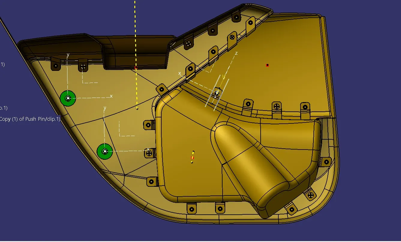
Material & Render- Material can be assigned to individual parts of door trim with appropriate texture & specifications. Catia also has a tool to render the output to get realistic visualization.