Week 12- Final project
FINAL PROJECT REPORT
AIM
The aim of this project is to make a solid body of a side door trim of a vehicle from the given class As of 4 parts of the door trim which are Lower Substrate, Bottle Holder, Map Pocket, and Door Armrest. Also, B side features like doghouse, heat stake and locator should be added, all obeying the design rules and guidelines. Also create the proper tooling axis for each part and do draft analysis on every parts.
INTRODUCTION
Plastic in Aotomotive Industry
The role of plastic in the design and manufacturing of automotive vehicles has never been more essential, with stringent regulations and changing consumer habits driving demand for more affordable, lightweight, and fuel-efficient vehicles. Fuel efficiency has become one of the most important features in automotive vehicle design due to the rising fuel prices and stricter environmental regulations.
There are two types of plastic used in automotive industry -
- Thermosets plastic
- Thermoplastic
Thermosets plastic -
Thermosets are formed when two or more components chemically react with each other under ambient conditions or when induced by radiation or heat to form a highly cross-linked network. The formation of thermosets is an irreversible process. Thermosets are typically hard and rigid. They tend to have higher temperature resistance when exposed to heat and will not creep or warp at higher temperatures compared to thermoplastics. Thermosets typically are used for structural applications where high strength and stiffness is required to resist high loads. Table 3.14 compares the properties of thermoplastics and thermosets.
Pros and Cons of Thermosets Plastic -
Pros -
- More resistance to high temperatures than thermoplastic
- High Flexible design
- Thick to thin wall capabilities
- Excellent aesthetic appearances
- High levels of dimensional stability
- Cost - effective
Cons -
- Cannot be recycled
- More difficult to surface finish
- Cannot be remolded or reshaped
Thermoplastic -
Thermoplastics are defined as polymers that can be melted and recast almost indefinitely. They are molten when heated and harden upon cooling. When frozen, however, a thermoplastic becomes glass-like and subject to fracture. These characteristics, which lend the material its name, are reversible, so the material can be reheated, reshaped, and frozen repeatedly. As a result, thermoplastics are mechanically recyclable.
Pros and Cons of Thermoplastic -
Pros -
- High recyclable
- Aesthetically - superior finishes
- High - impact resistance
- Remolding / Reshaping capabilities
- Chemical resistance
- Eco - friendly manufacturing
Cons -
- Generally more expensive than thermoset
- Can melt if heated
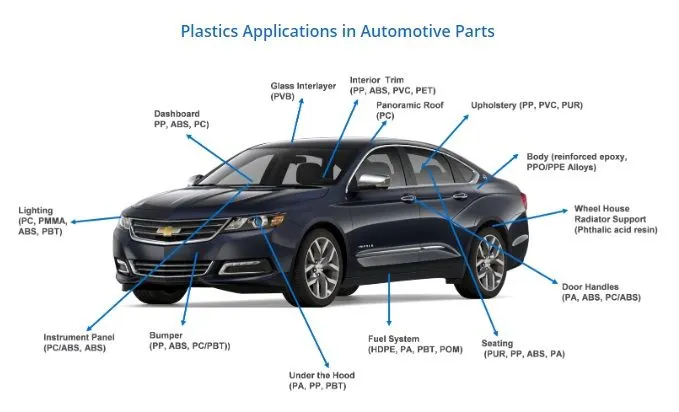
The most common plastics used in an Aotomotive Industry -
- PC (Polycarbonate)
- PP (Polypropylene)
- PVC (Polyvinyl Chloride)
- ABS (Acrylonitrile butadiene styrene)
- PBT (Polybutylene terephthalate)
- PVB (Polyvinyl butyral)
- PET (Polyethylene Terephthalate)
- PUR (Polyurethane)
- PPO/PPE Alloys
- PA
- PMMA
- POM
- HDPE
Manufacturing Process for Platic used in Aotomotive Industry -
These are the different manufacturing process for plastic -
- Injection molding
- Compression molding
- Extrusion molding
- Rotational molding
- Blow molding
Injection molding are the major manufacturing process in whole of the plastic industry and 90% of Auromotive Components are manufactured by Injection Molding -
Injection Molding -
Injection molding is the process of making plastic parts by injecting molten plastic material at high pressure into a metal mold. After the molten plastic is injected into the mold, the mold is cooled and opened and a solid plastic part.
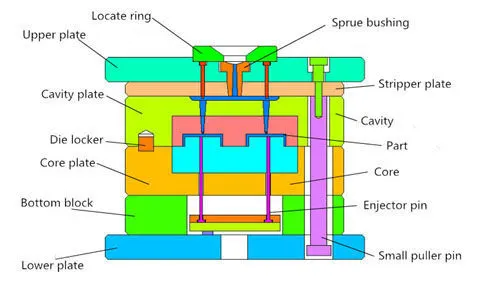
Parts of an Injection Molding Machine -
- Cavity and Core Plate
- Sprue bush
- Runner and gate System
- Register ring
- Guide Pillar and bushes
- Top Plate
- Bottom Plate
- Ejection System
Working Principle -
- Clamping
- Injection
- Dwelling
- Cooling
- Mold Opening
- Ejection
- Clamping
Tooling Direction -
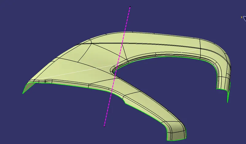
Tooling direction is the direction the mould takes to make the part. It is basically the direction that the mould pulls apart. The mould is built in two separate pieces, a cavity side and the core side. The core pulls apart from the cavity and that is the Tooling Direction.
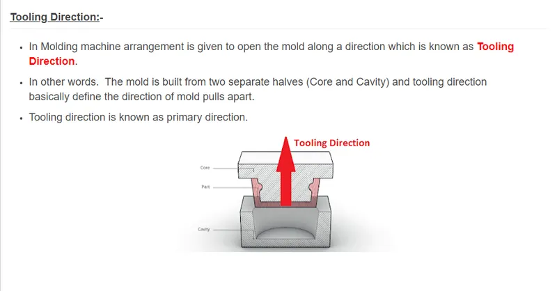
Core is the male part which forms the internal shape of the moulding. Cavity is the female part that forms the external shape of moulding.
Parting line is the line of separation on the plastic part where the two halves of the plastic injection mould meet, i.e. where the core and cavity meet.
Design for Manufacturing & Assembly (DFMA)
Design for Manufacturing and Assembly is an engineering methodology that focuses on reducing time-to-market and total production costs by prioritizing both the ease of manufacture for the product’s parts and the simplified assembly of those parts into the final product – all during the early design phases of the product lifecycle.
Before becoming the singular philosophy it's known as today, DFMA used to be considered as two distinct methodologies: Design for Manufacturing (DFM) and Design for Assembly (DFA).
DFM is concerned with selecting cost-effective raw materials and attempting to minimize the complexity of manufacturing operations during the product design phase in order to reduce the overall manufacturing time and costs for product components. Similarly, DFA is concerned with reducing the product's assembly time, costs, and complexities by minimizing the number of individual parts, assembly steps, and the potential for variability in build quality.
Function of Heat Stake, Locator, Doghouse, and Ribs -
Heat Stakes
Heat staking also known as thermoplastic staking is the process of joining two dissimilar materials together. In heat staking we use local heating and cooling to raise the temperature of plastic components and allow plastic reforming to be carried out. This reforming can be used in a wide variety of applications.
Applications range from staking plastic bosses for assembly of car door panels to joining PCB’s to plastic housings. Benefits of this technique include; no vibration damage, no particulates, the ability to stake metalized coated applications and the capability to stake in difficult to access or restricted areas.
Locators
Locators provide a positive stop for the workpiece. Placed against the stop, the workpiece cannot move. Clamps, on the other hand, rely only upon friction between the clamp and the clamped surface to hold the workpiece. Sufficient force could move the workpiece.
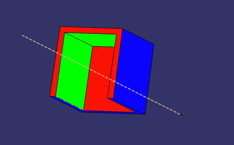
3-2-1 Principle:
Locating Process: In order to completely specify the position in space of a three-dimensional object (such as the cube that’s shown), we refer to six coordinates with total 12 degrees of freedom.
- Translational position along the X-axis
- Translational position along the Y-axis
- Translational position along the Z-axis
- Rotational position about the X-axis
- Rotational position about the Y-axis
- Rotational position about the Z-axis
These six coordinates are known as the six degrees of freedom of a three-dimensional object. As the double-headed arrows indicate, the translational and rotational positions can vary in either direction with respect to each of the three axes. To completely prevent movement, all six degrees of freedom must be restricted.
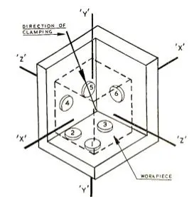
So locators are basically used to arrest the degree of freedom of the component.
There are two types of locators -
1.) 4- way locators - A round locating pin located concentrically in a hole is a common application of a 4-way pin, and helps to further secure the piece. 4-WAY LOCATORS: 4-way mean you prevent movement at 2 axes (+X, -X, +Y and -Y) on the plane. Generally, you have cylindrical pin on the fixture and circular hole at workpiece part.
2.) 2- way locators - A 2-way locating pin restricts motion along 1 axis (or 2 degrees of Freedom), like a round pin in a slot. Likewise, a 4-way pin restricts 4 degrees of freedom along 2 axes.
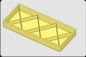
Dog House
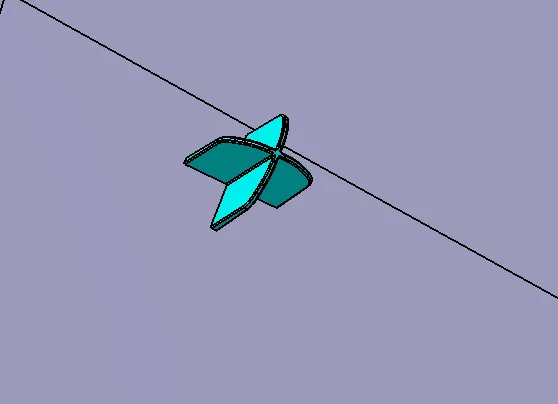
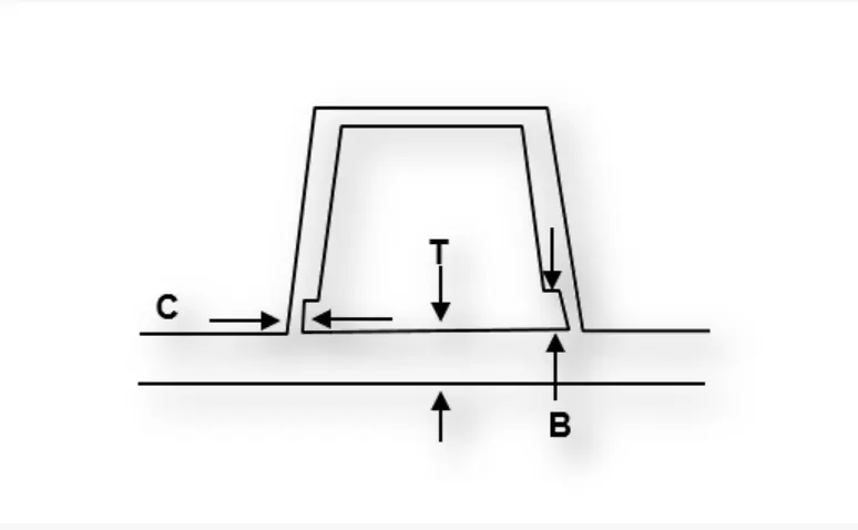
The dog-house is an engineering feature used in the plastic trim design that is used as a supporting feature. Sometimes other engineering features like snaps; locators etc. are mounted on them to increase their strength. Usually, this engineering component is built on the B-surface and is subjected to draft analysis to prevent breakage of the component during ejection from the mould cavity.
Ribs
Ribs are used to strengthen the walls of your mould without increasing wall thickness which means that you minimise the problems that come into play when the wall thicknesses have to be increased.
DESIGN PROCEDURE FOR DEVELOPMENT OF A DOOR TRIM PANEL
In a Door Trim Panel, There are four parts of Door Trim Panel and we have to work one by one on each parts.
- Lower Substrate
Let's create the lower substrate for door trim panel -
Class-A Surface -
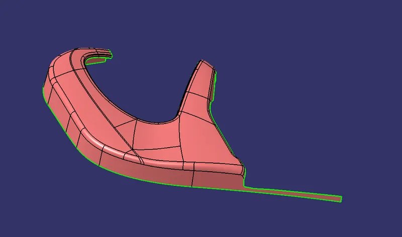
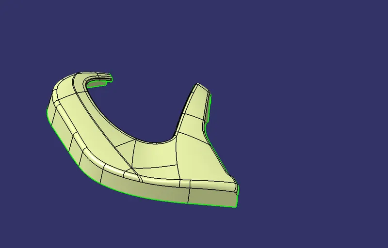
Remove the extra portion of class-A surface -
Tooling Axis -
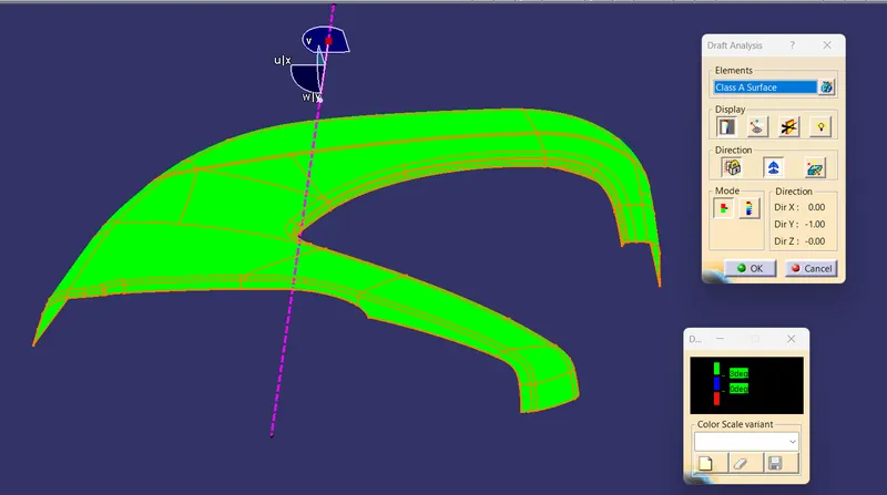
Draft Analysis on Class-A Surface -
Class B Surface -
create class B Surface by offsetting Class-A Surface -
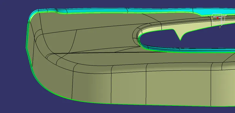
Class c Surface -
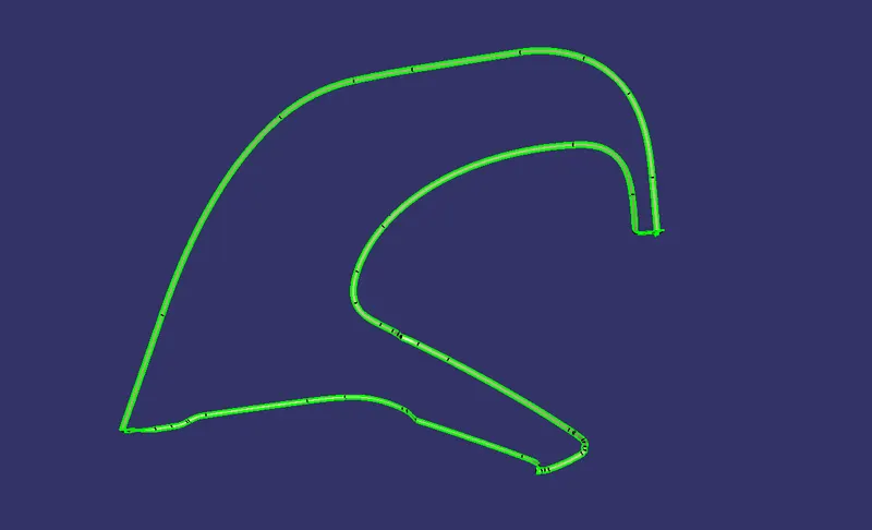
Closed Surface -
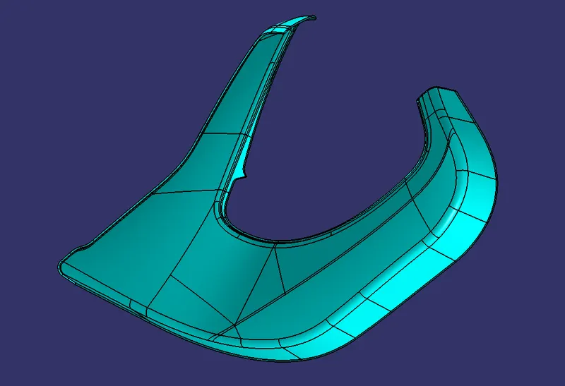
Lower Substrate Solid Body -
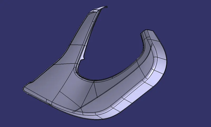
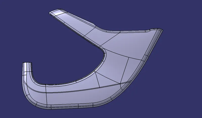
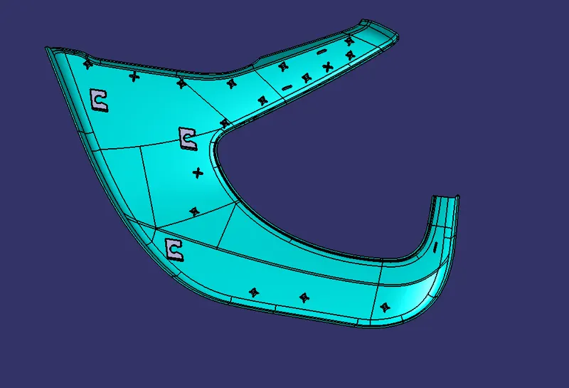
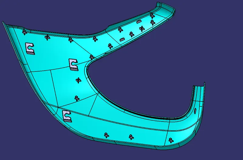
Now Creates the Heat Stakes, Locators and Dog Houses with Tooling Direction -
Heat Stakes -
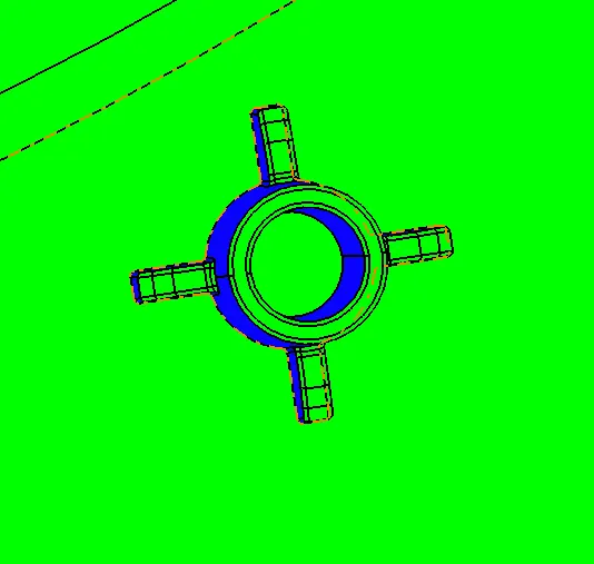
Locators -
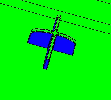
Dog House -
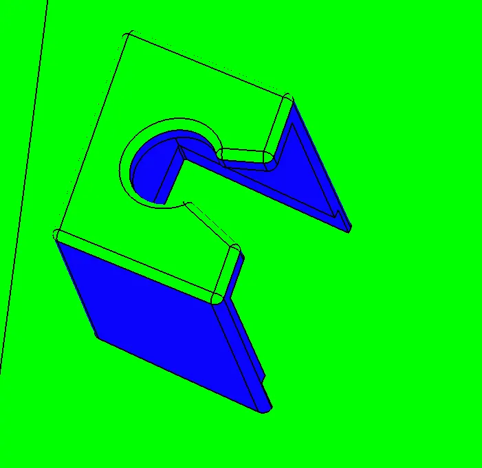
Dog House Inner Surface -
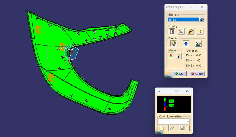
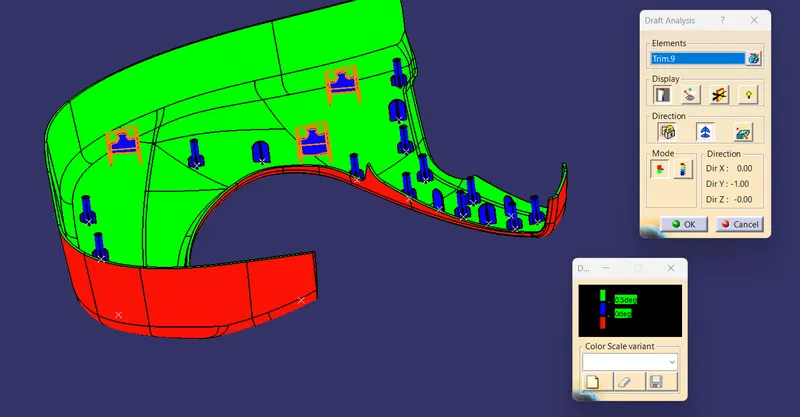
Now do the draft analysis on Final Component -
3 degree
0.5 degree
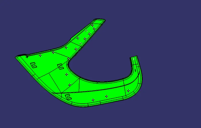
Final Component -
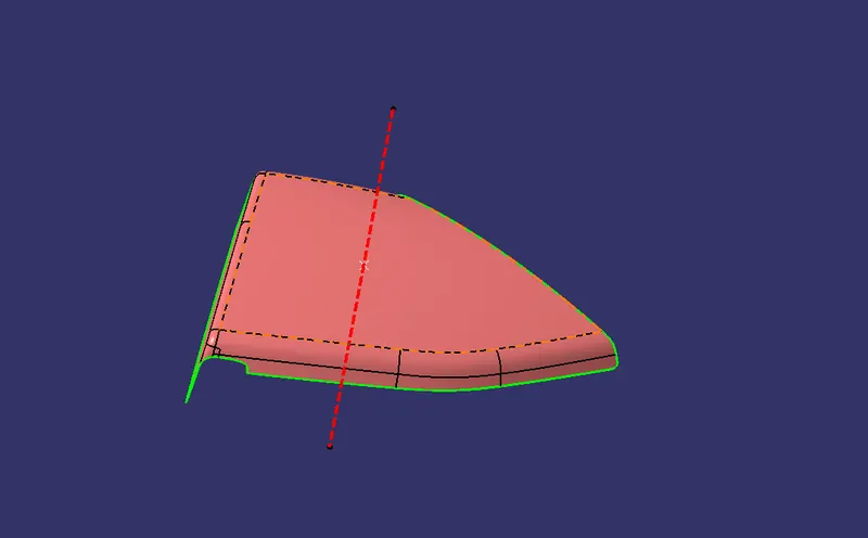
- Map Pocket
Class-A Surface -
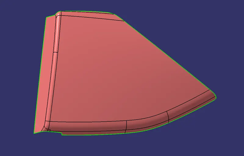
Tooling Axis -
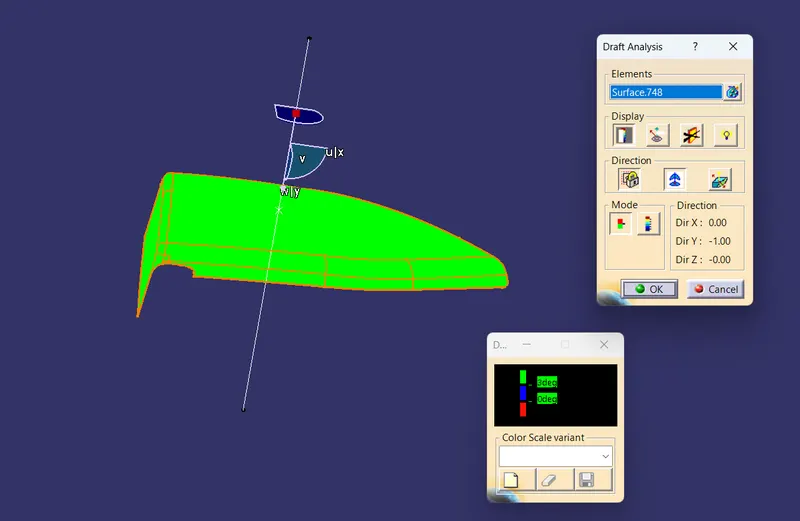
Draft Analysis on Class-A Surface -
Class B Surface -
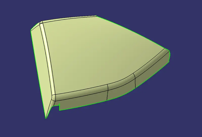
Class C Surface -
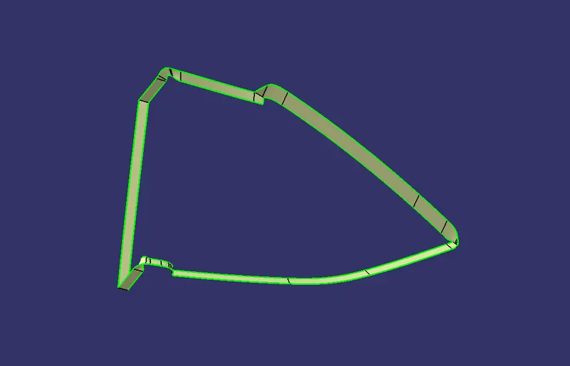
Closed Surface -
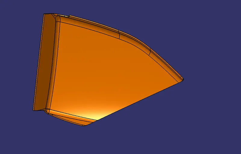
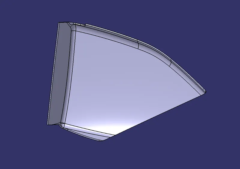
Map Pocket Solid Body -
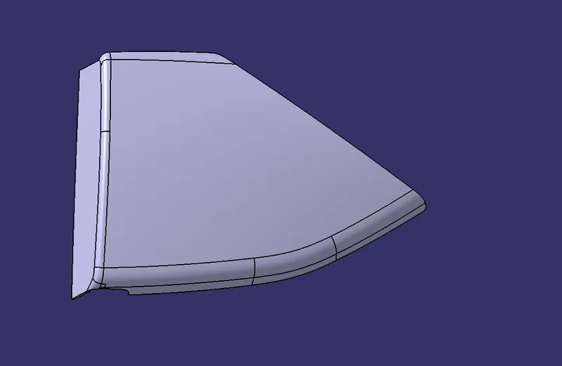
Now create Flanges for attachments -
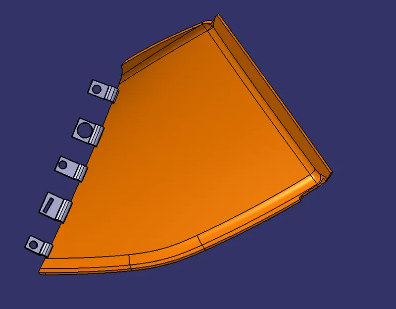
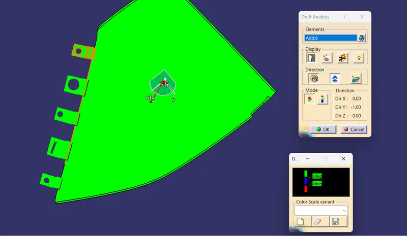
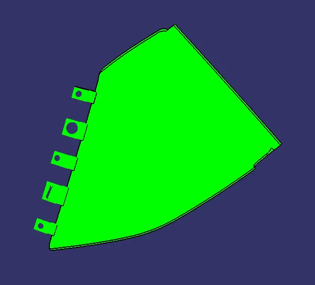
Draft Analysis on Final Component -
- Bottle Holder -
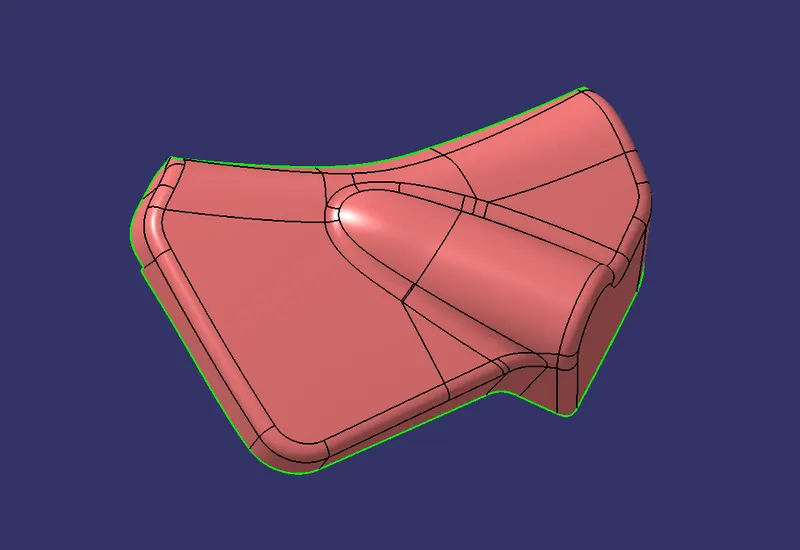
Class-A Surface
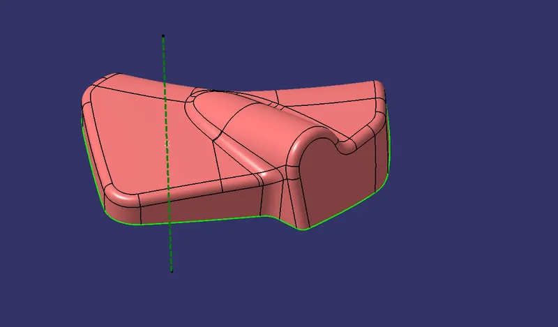
Tooling Axis -
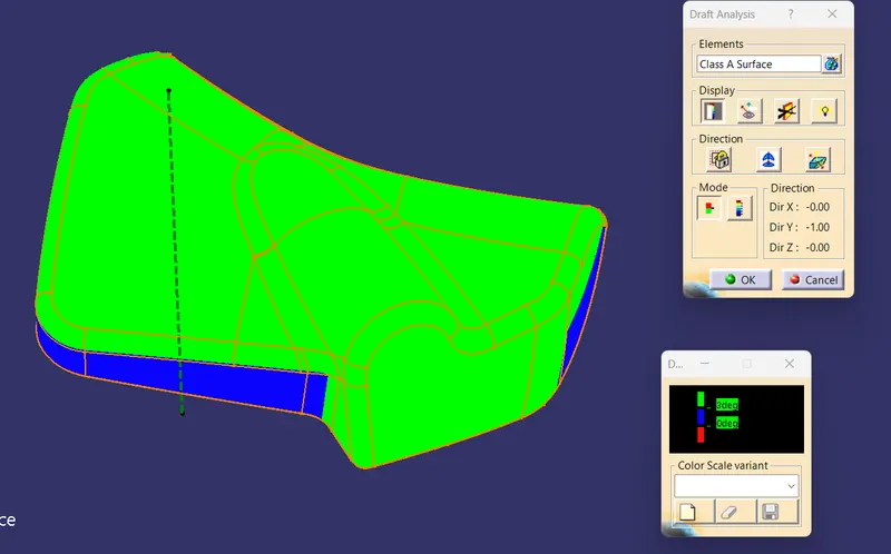
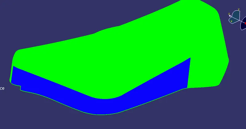
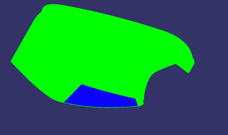
Draft Analysis on Class-A Surface -
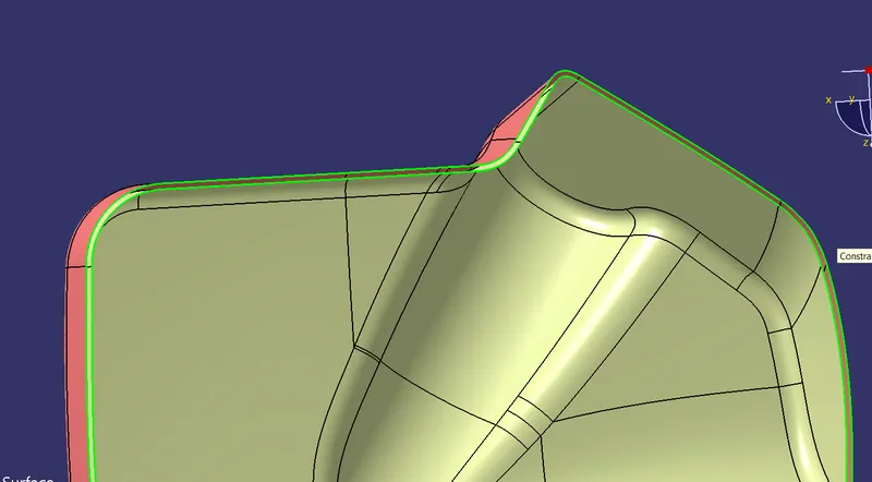
Class B Surface -
Class C Surface -
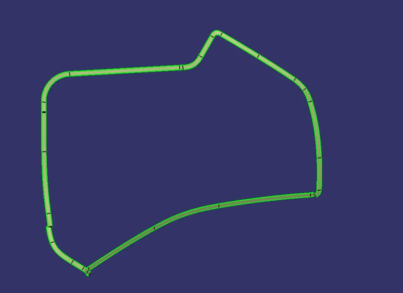
Closed Surface -
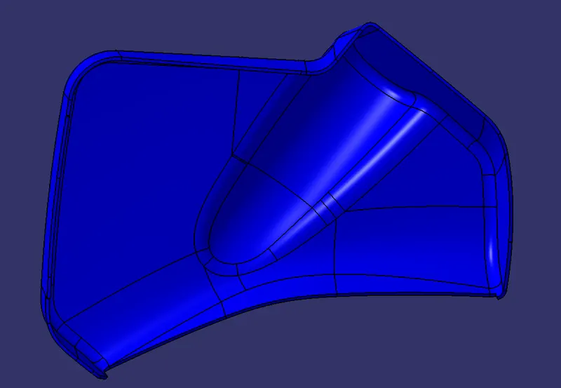
Bottle Holder Solid Body -
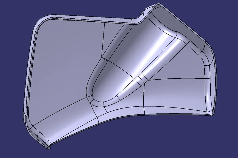
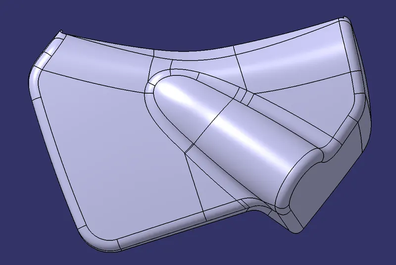
Now create Flanges for attachments -
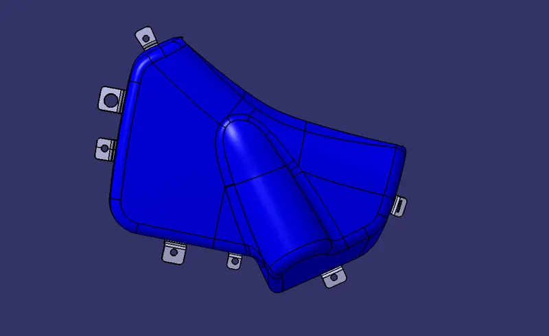
Draft Analysis on Final Component -
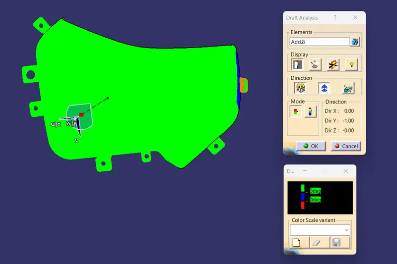
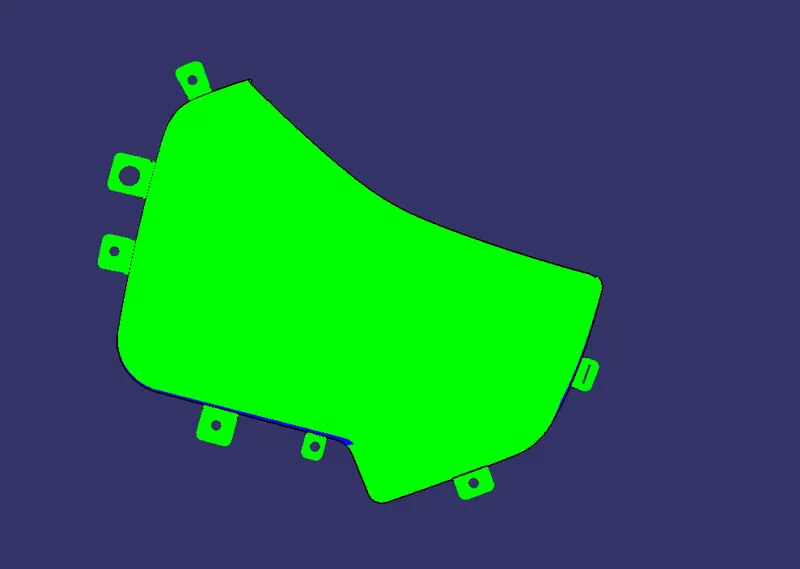
- Door Armrest
Class-A Surface
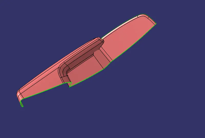
There are some pathces on class A surface -
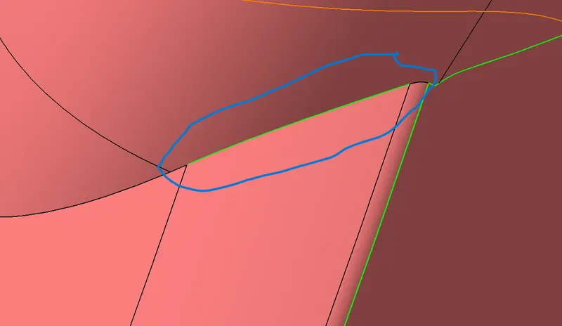
let's do some modification to clear the patches -
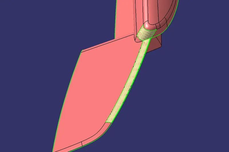
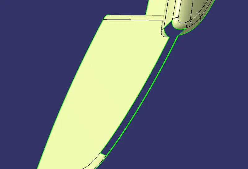

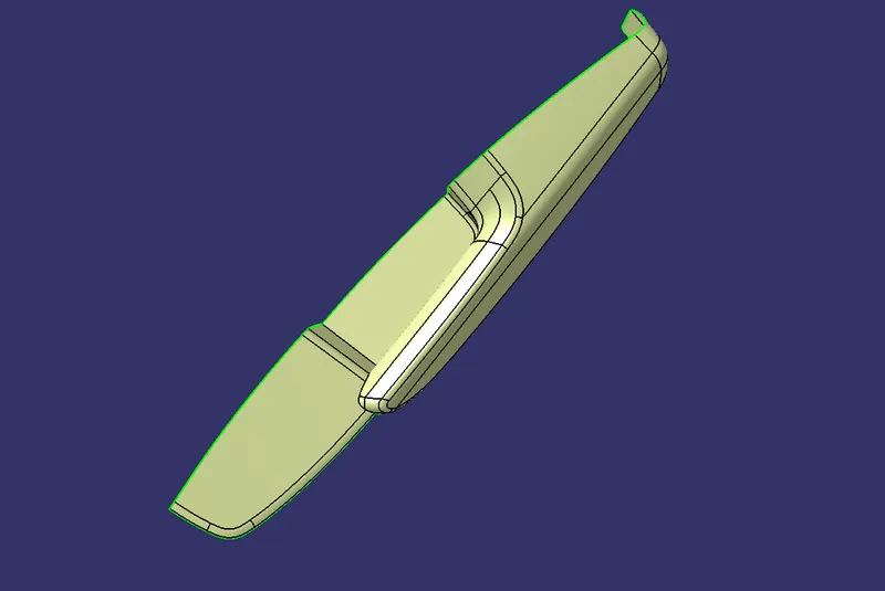
Tooling Axis -
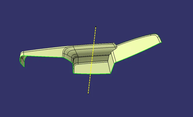
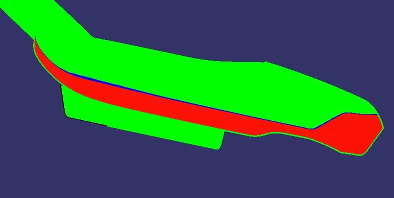
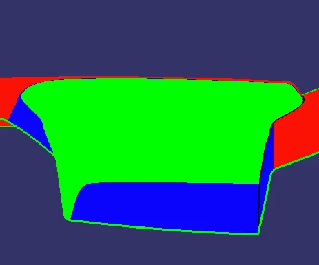
Draft Analysis on Class A Surface -
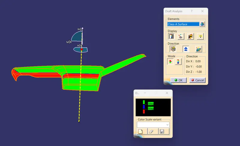
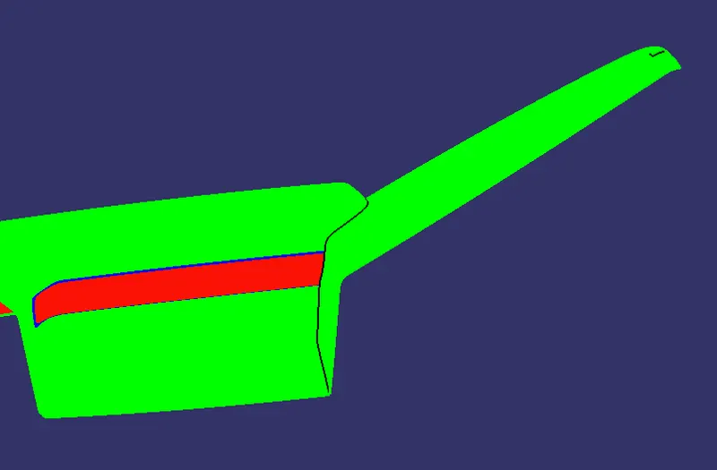
here some area has negative draft -
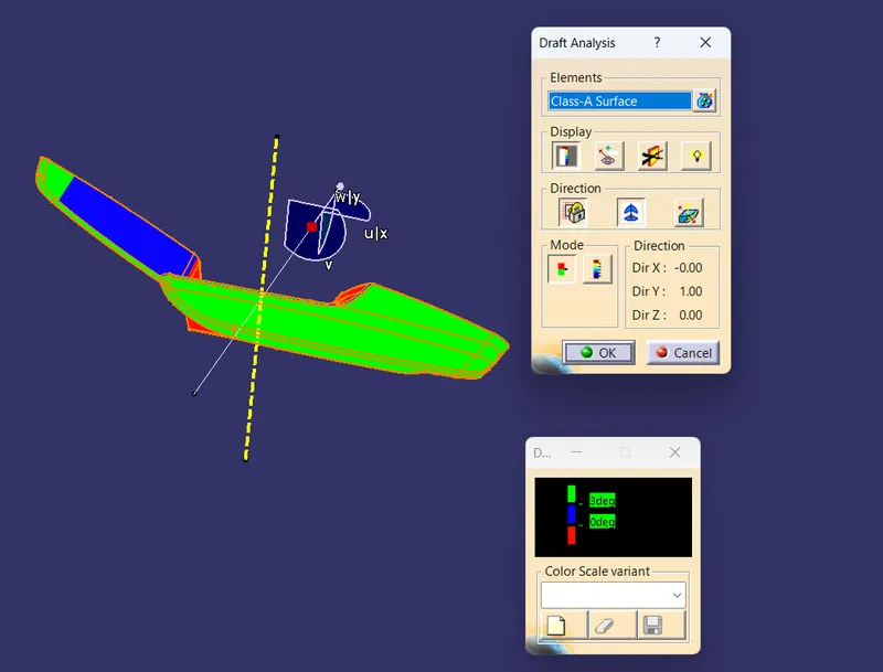
let's create side tooling axis for clearing this area -
Class B Surface
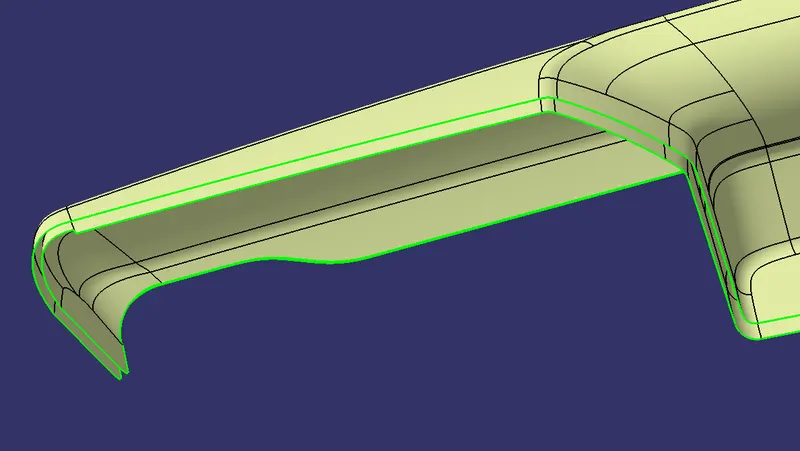
Class C Surface
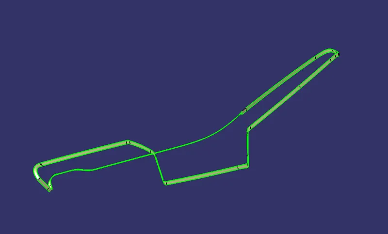
Closed Surface
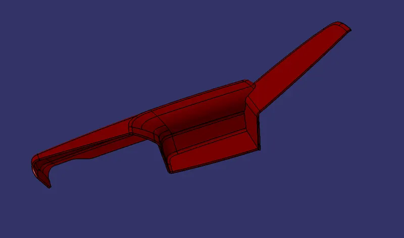
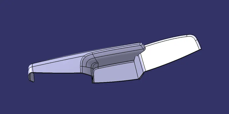
Door Armrest Solid Body
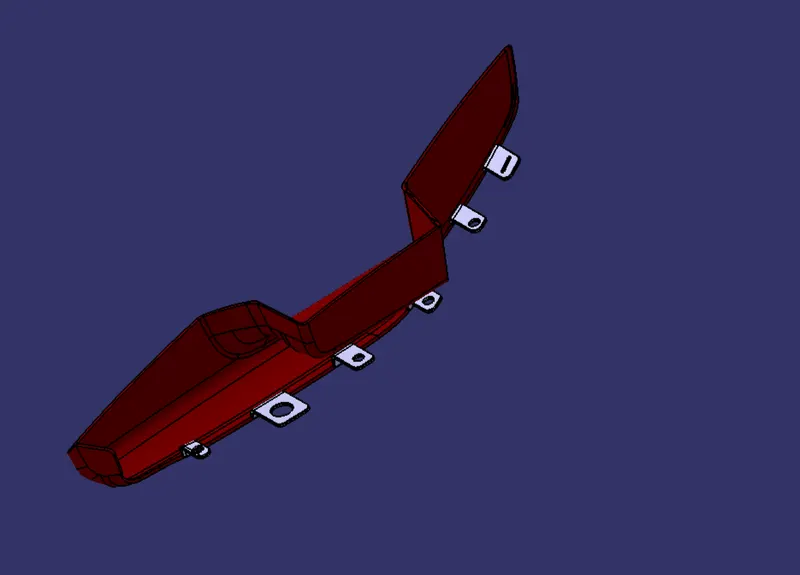
Now create the Flanges for attachments
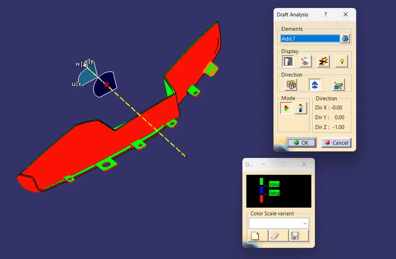
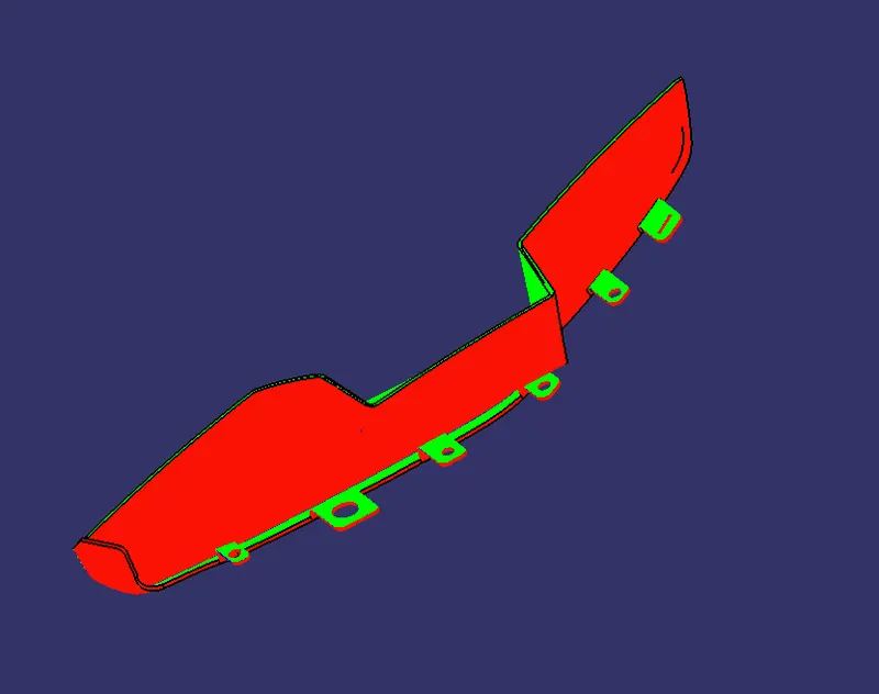
Draft Analysis on Final Component -
Now assemble all the parts in a single product file -
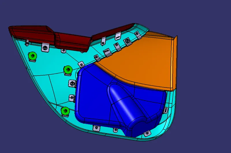
CONCLUSION
We have discussed about the plastic in Aotomotive Industry. Then we discussed about the different engineering B side features. we create all the parts Lower Substrate, Map Pocket, Bottle Holder and Door Armrest and also create the engineering B side features for Lower Substrate. Then we Created the flanges for attachments. We have also do the draft analysis for each part files.