Week 12- Final project
OBJECTIVE:
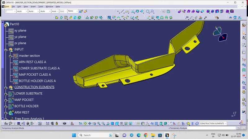
Development of door trim panel.
GIVEN CLASS A SURFACE WITH MASTER SECTION:
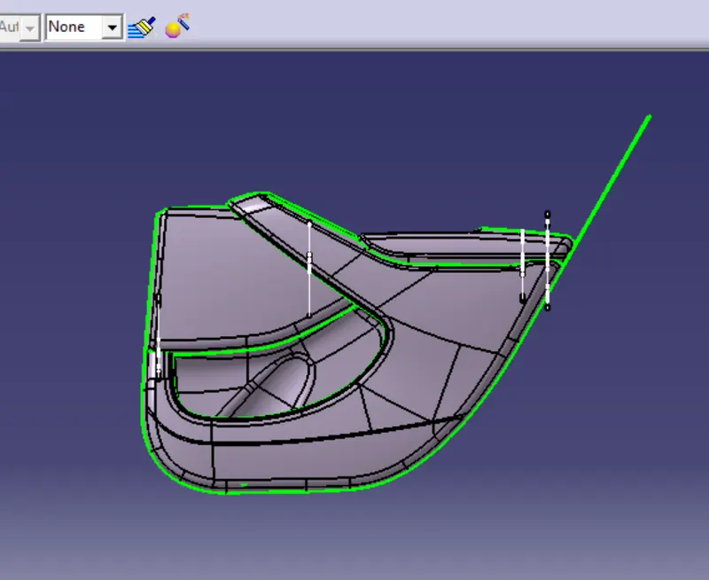
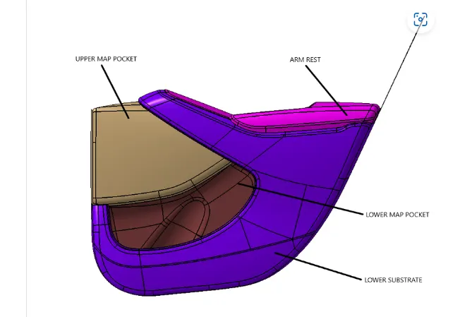
PROCEDURE FOLLOWED FOR THE CREATION OF COMPONENTS:
- Analyse the input surface provided
- Class A surface as input surface
- Tooling axis creation
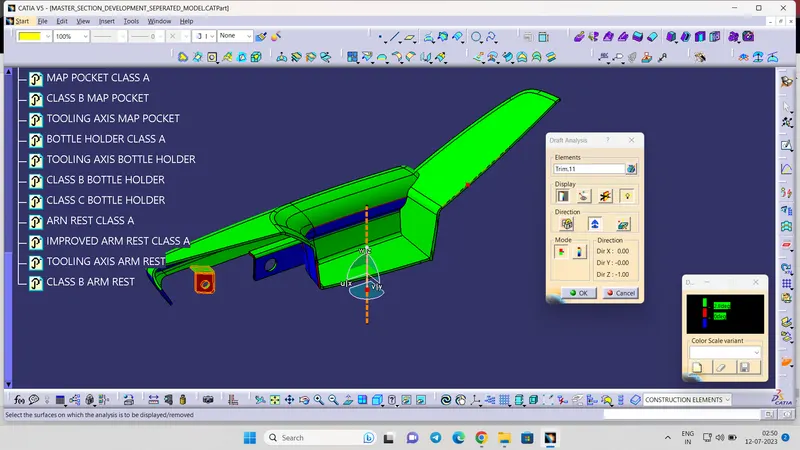
- Draft analysis of class A surface
- Class B surface creation
- Class C surface creation
- Solid surface body generation
- Draft analysis of the solid body
- creating the B side features
- Draft analysis of the solid body along with the B side features.
CLASS A: Class A surface is an asthetic surface which is visible for the customer in the component
CLASS B : Class B surface is an engineering surface where the B side features of the components like heat stakes, screw bosses, Ribs, doghouses are situated.
CLASS C : Class c surface lies as an intermediate surface between the class A and the class B surface thet means it generally accommodate the thickness of the whole plastic component
HEAT STAKE: These are petrutions made to as to plastic weld the parts with simple heat aplication
DOG HOUSE : engineering feture that is used to support features that require a raised position from main body
LOCATOR : These are petrutions that are used to place the parts to the correct location with ease,. it also helps to lock and keep only 1 degree of motion.
PART 1: LOWER SUBSTRATE:
1: GIVEN CLASS A
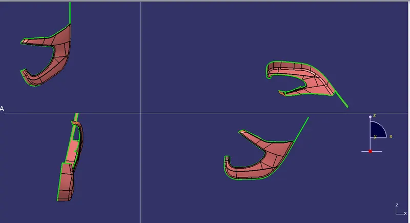
Check for any pathes no patches found,
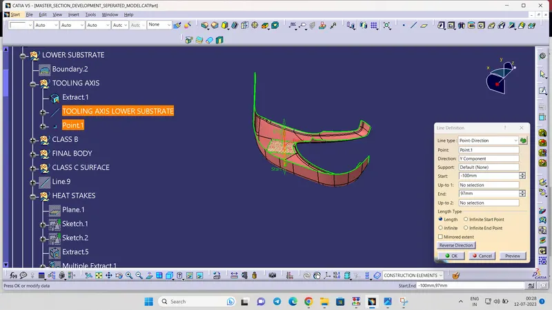
2 : TOOLING AXIS CREATION:
- The posible tooling axis is in y direction so extract the face and create an dummy tooling axis.Check wheater the tooling axis is a ok or not.
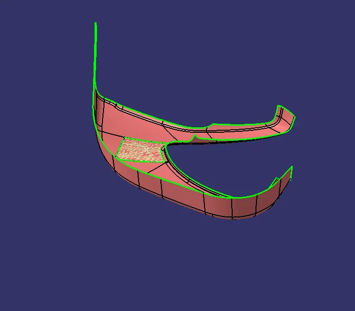
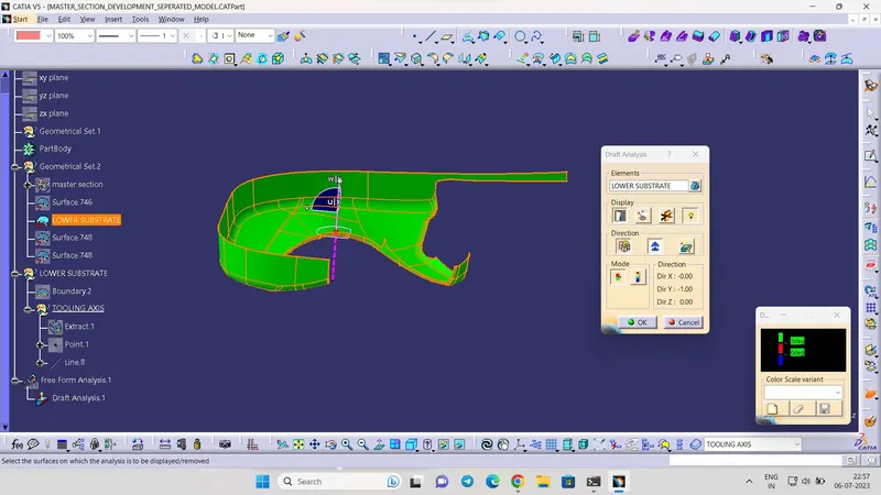
3: DRAFT ANALYSIS OF CLASS A:
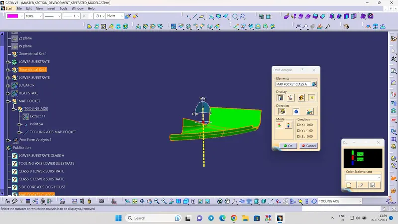
- The draft angle is the amount of taper perpendicular to the parting line for molded or cast parts.
PROCEDURE:
- First change the created part into material.
- Click on the compas and plase in the tooling direction.
- Use the lock command to fix the compass
- Click on the surface and apply the draft angle
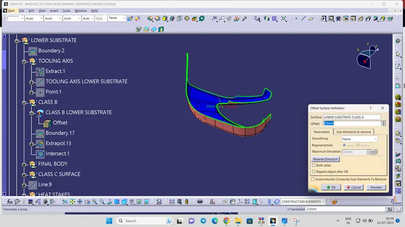
4.CREATION OF CLASS B:
- Class b is created by offseting 2.5 mm
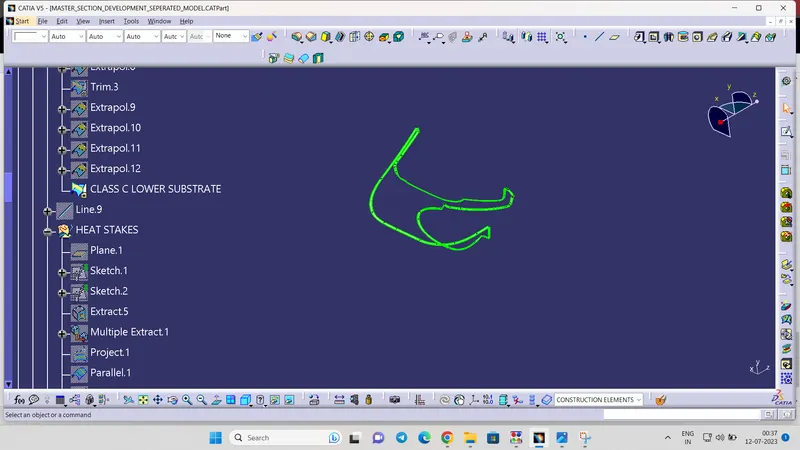
5.CREATION OF CLASS C:
- The A and B surfaces are connected by another single surface which is called the C surface
- Class c is created using sweep command
- Here the sweep done in draft ditection and with reference to the surface.
6:CREATION OF SOLID BODY:
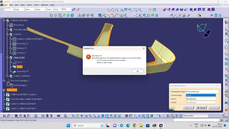
- The solid body is created using close surface feature.
- Boundary is selected and the body is picked. Since an error popped up it can be understood that all surfaces are joined with each other to form a proper closed surface body
As per the master section heat stake dog house and locator are placed in lower substrate b surface.
7:CREATION OF DOG HOUSE:
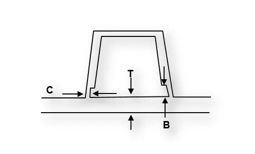
- Doghouse is an engineering feature used in the plastic trim design which helps to remove sink marks formed on Class-A surface while creating attachment feature on Class-B surface. Doghouse is a supporting feature, other features like locators, heat stakes, pushpins are mounted on top of doghouse for fixing and assembly purpose
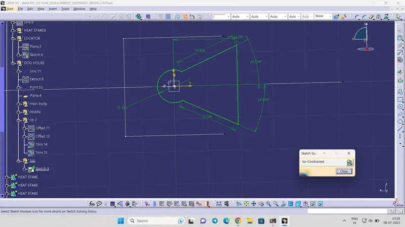
- For creating dog house an surface is extracted and create an point .a skectch created on that point and sweep it
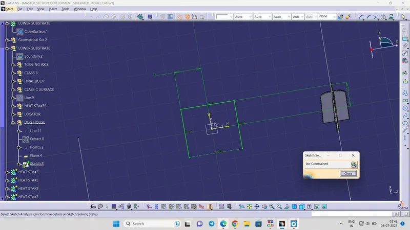
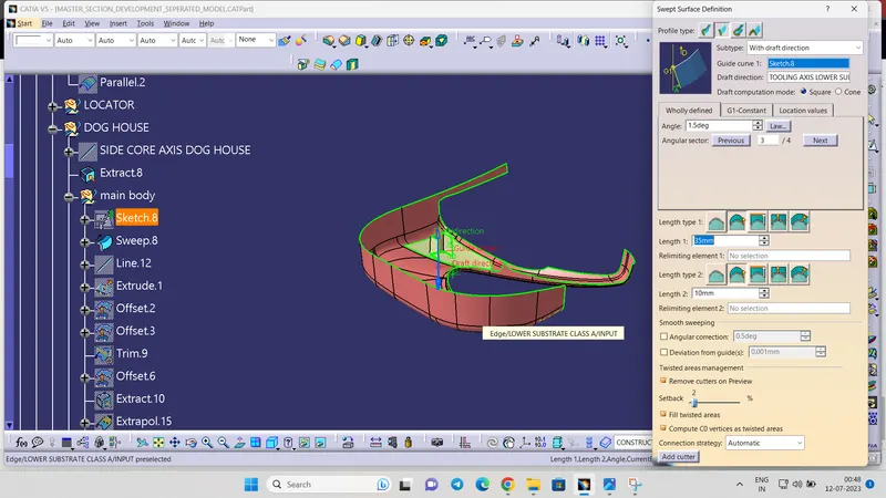
- create an closed surface which is suitable for position the push clip.
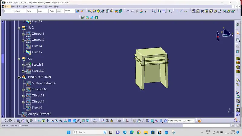
- the top portion is cut with help of a sketch which is suitable for place push clip .and finally create a solid body from it
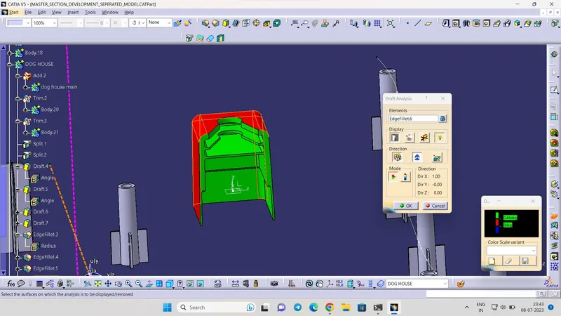
- A side core axis also created .after giving proper draft draft analysis also cheaked.proper cutting also provided for the dog house at the bottom.
8. CREATION OF HEAT STAKE;
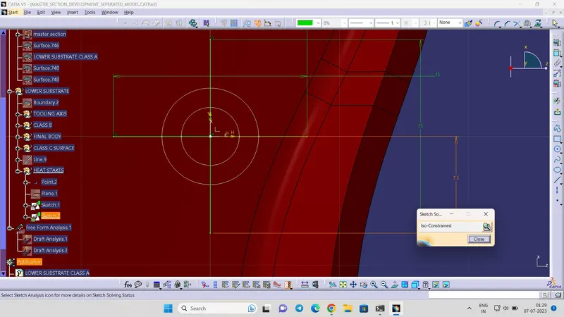
- For creating heat stake follow the master section, as per master section create an sketch and pad it provide suitable rib also
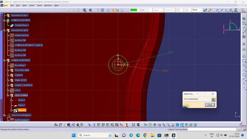
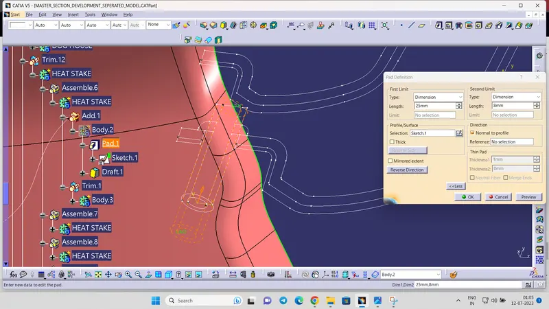
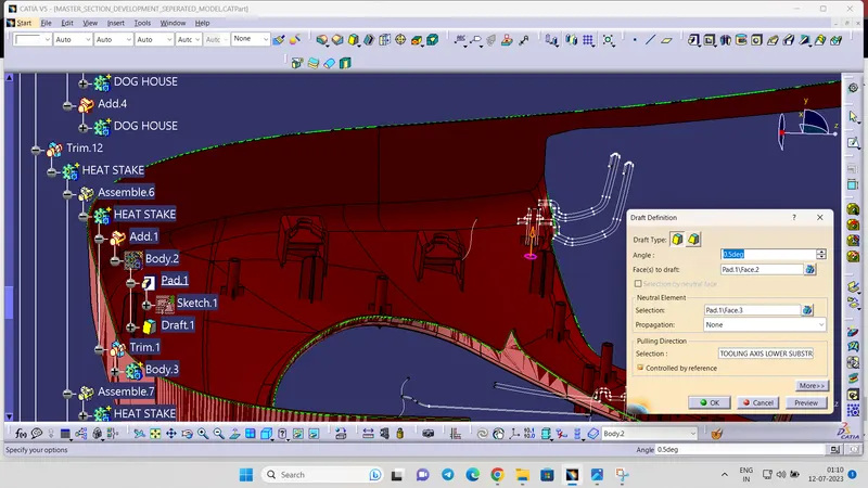
- After pad provide nesessary draft also.5 is given draft
9. LOCATOR CREATION:
- For creating the locator a sketch is created and then pad it. the height must be 5 mm taller than heat stake.
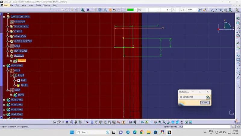
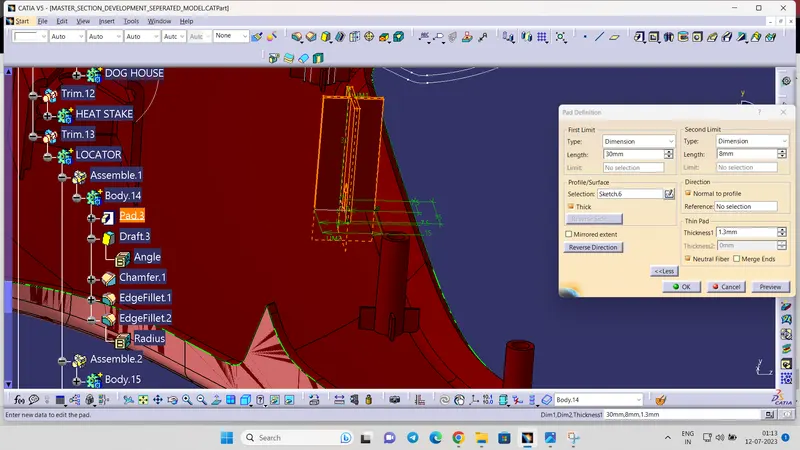
- Provide proper draft for locator also
- Afte the creation of all the attachment feature place them in proper positions with help of copy paste,and transilation command.
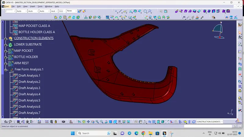
10.DRAFT ANALUSIS ON FINAL BODY:
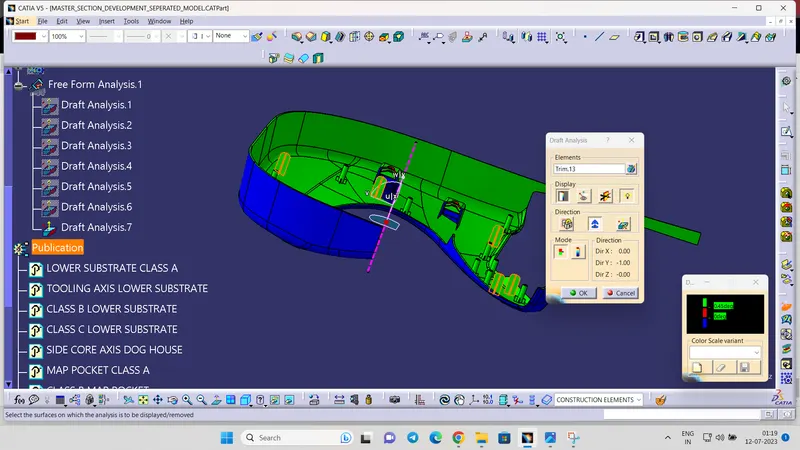
PART 2:MAP POCKET:
1:GIVEN DATA
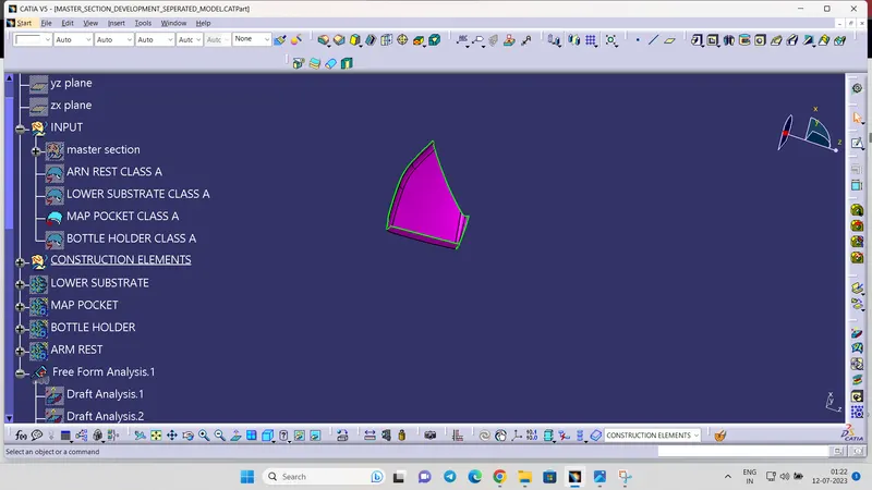
No patch found,
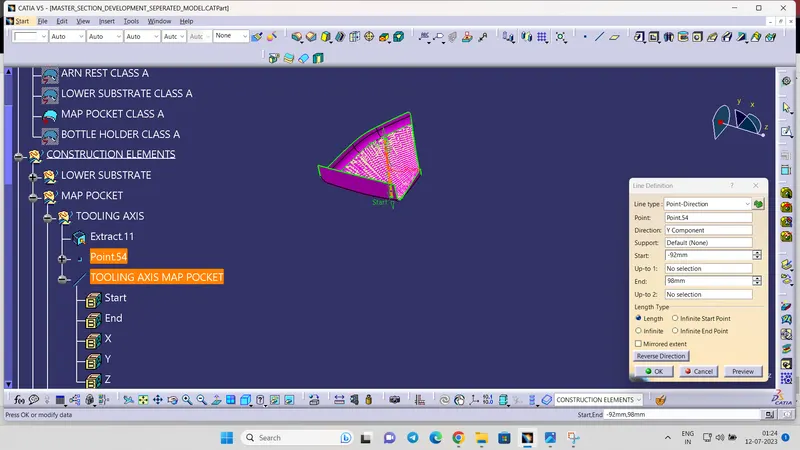
2. TOOLING AXIS CREATION:
- for creating tooling axis i extracted an suface and create an point .through that point create the toolig axis and check the draft analysis.
3.DRAFT ANALYSIS OF CLASS A:
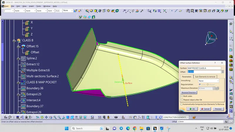
4.CREATION OF CLASS B;
- Class b is created by offseting 2.5 mm
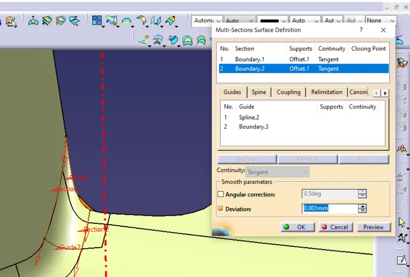
- an patch is formed using multi section solve it,
5.CLASS C SURFACE:
- The A and B surfaces are connected by another single surface which is called the C surface
- Class c is created using sweep command
- Here the sweep done in draft ditection and with reference to the surface.
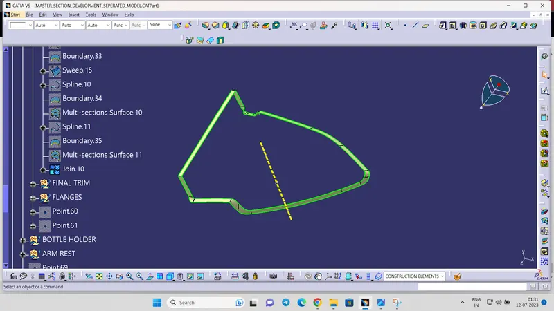
6.CREATION OF CLOSED SURFACE:
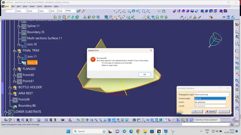
7. CREATION OF FLANGES:
- Flannges are created as per the master section
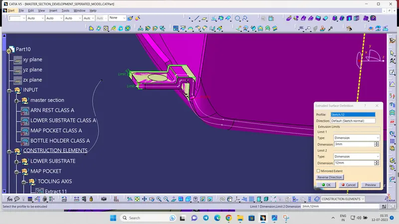
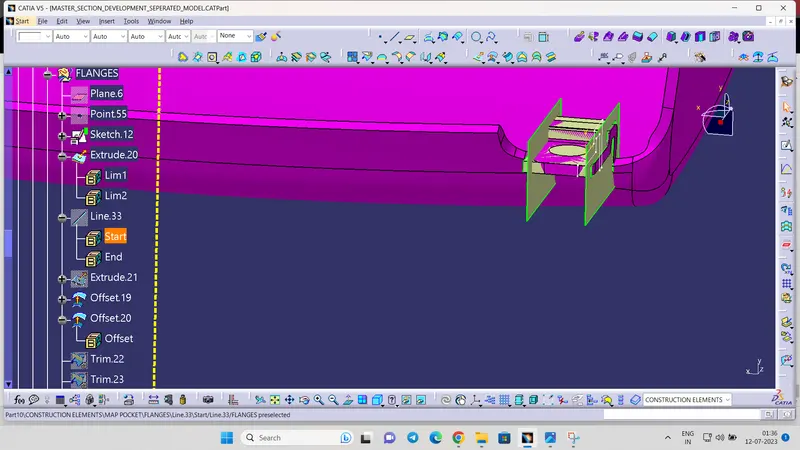
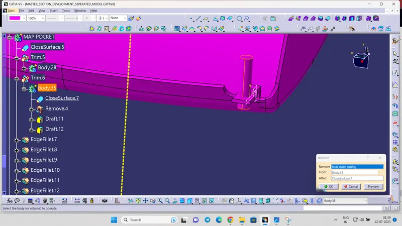
- for clearence for heat stake proper hole is created using an paded body and remove command.
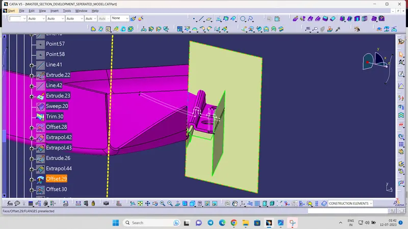
- Similarly hole also created for the flanges.
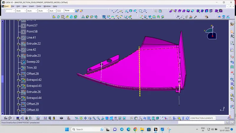
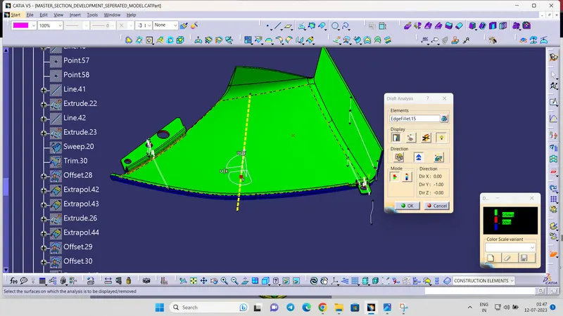
8.DRAFT ANALYSIS ON FINAL BODY:
PART 3. BOTTLE HOLDER:
1.GIVEN DATA
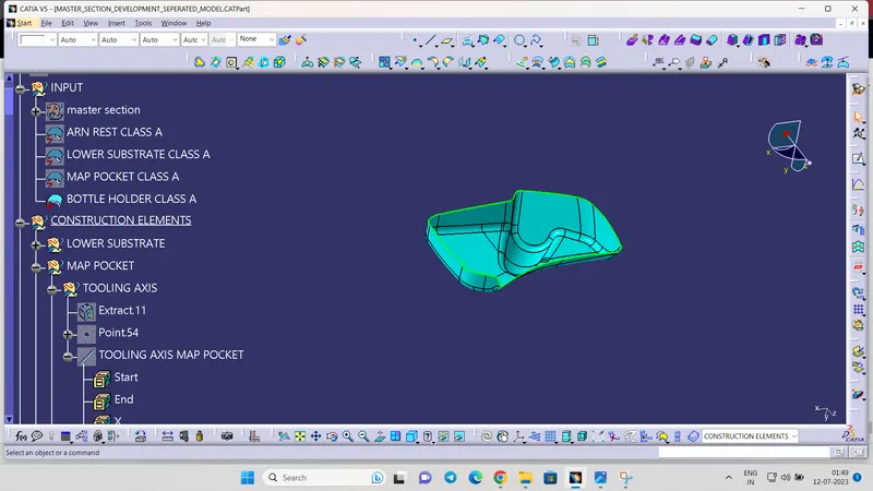
No patch found
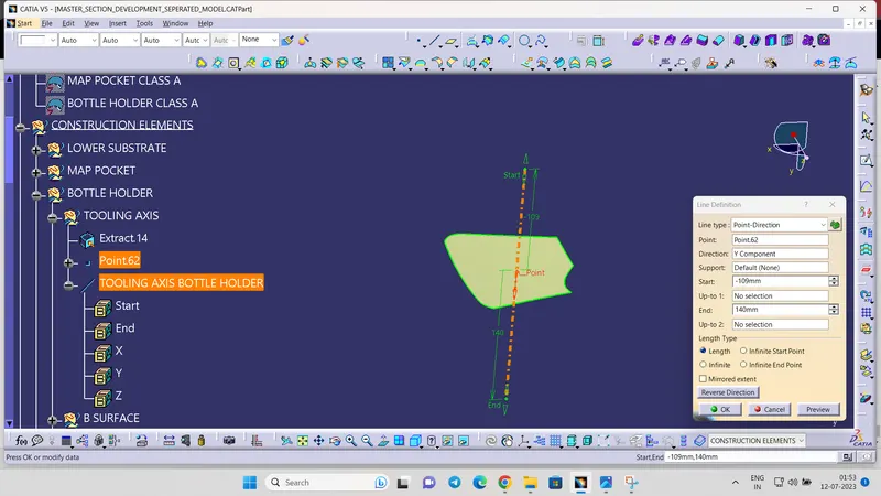
2. TOOLING AXIS CREATION;
- For creating tooling axis i extracted nn surface and created an point on that surface. aline created through that poin and check draft analysis.it satisfy so it considerd as main tooling axis
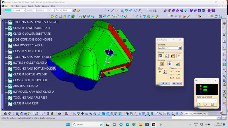
3 DRAFT ANALYSIS OF CLASS A:
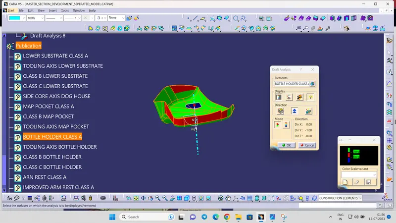
- To be notted that the draft angle is not been satisfiying 3degree. so the data must be send back to the Class A surface designer
4.CREATION OF CLASS B SURFACE:
- Class b surface is created by offseting 2.5mm
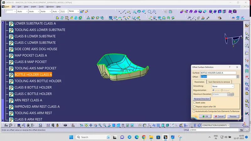
5.CREATION OF CLASS C SURFACE:
- Class c surface is created by sweep with reference to the surface .becouse the edges extrapolating in draft direction.
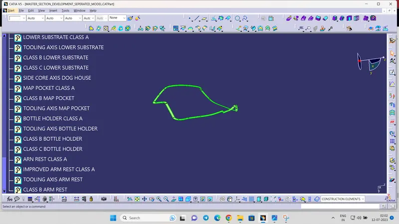
6.CREATION OF CLOSED SURFACE:
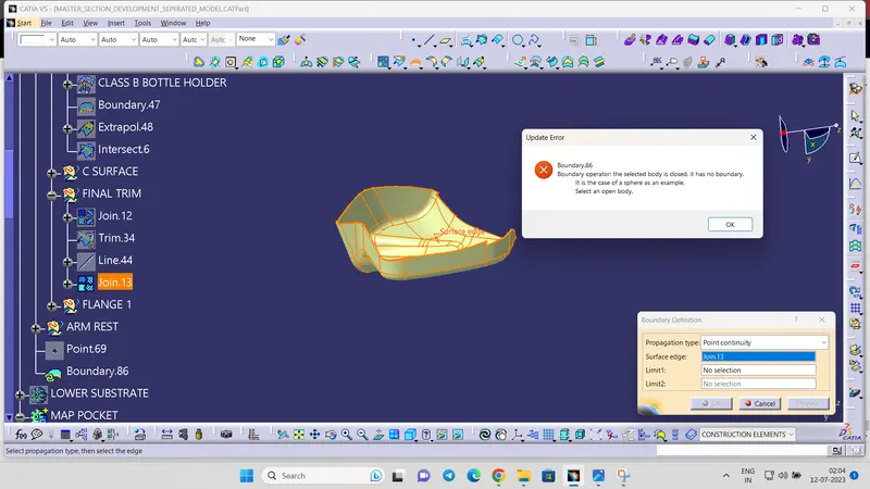
- The closed surface then converted into solid structure
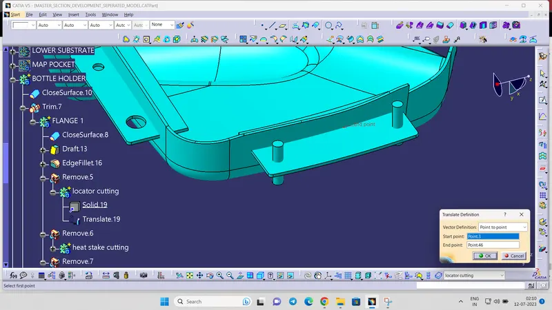
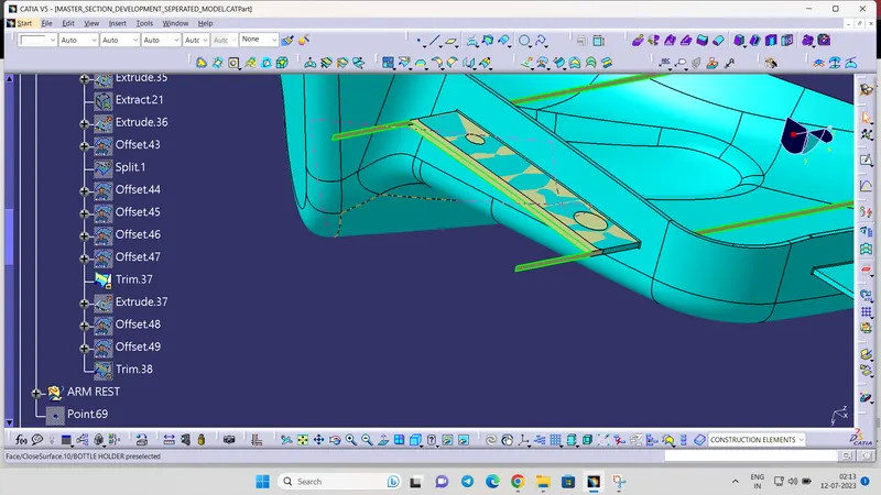
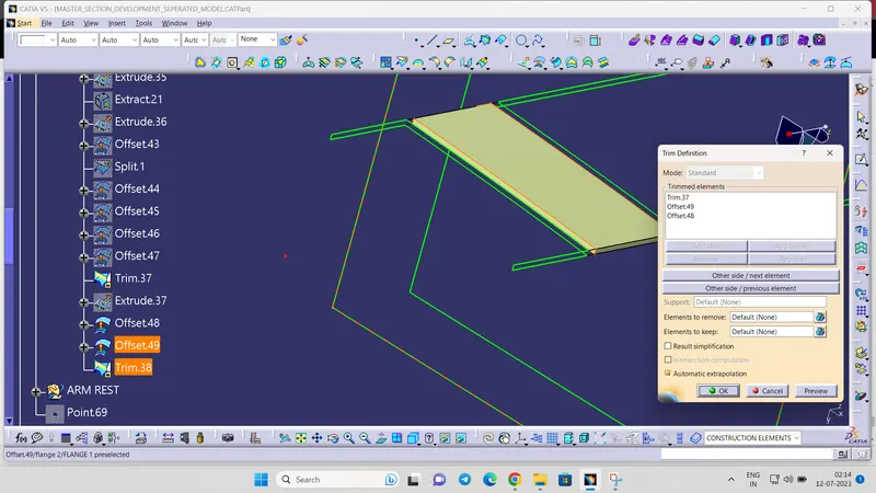
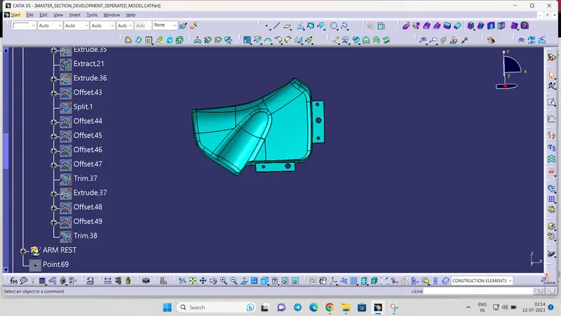
7. CREATION OF FLANGE:
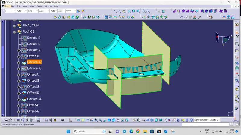
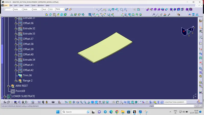
- Hole is created on the flange .using a padded cyliner similar size of the hole removed from the flange.
8.DRAFT ANALYSIS OF FINAL BODY:
PART 4. ARM REST
1.GIVEN DATA:
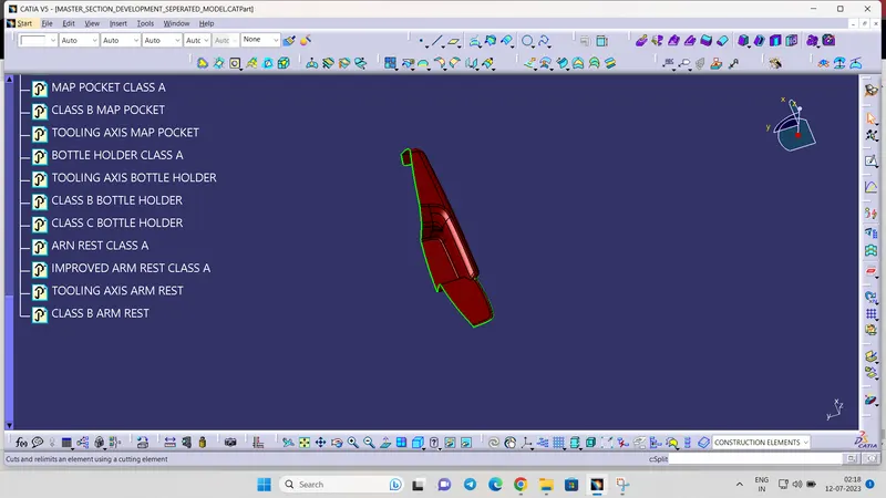
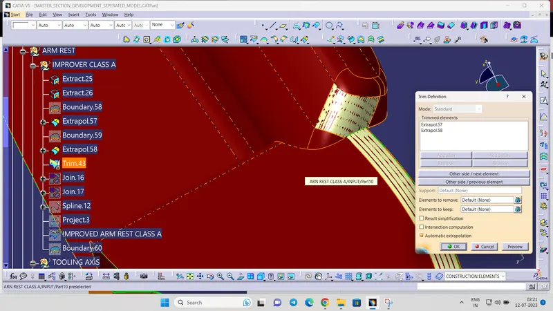
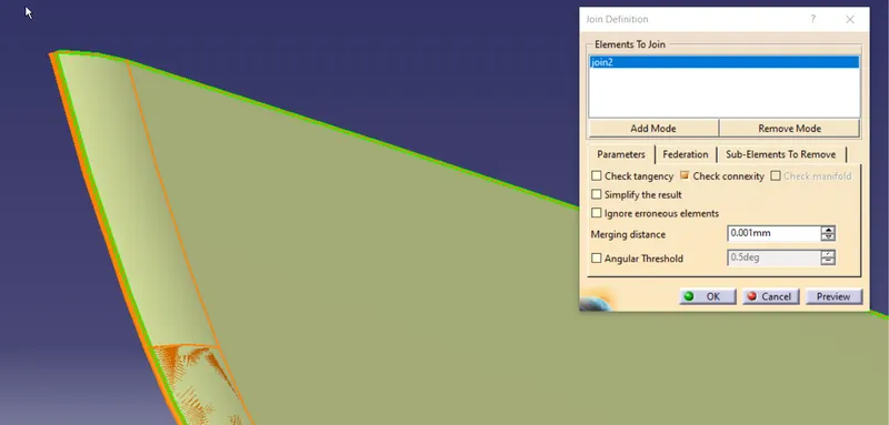
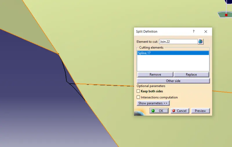
- There seem to be a small gap form. Need to be correct it ,extract surface, create border and extrapolate, trim and join the surface
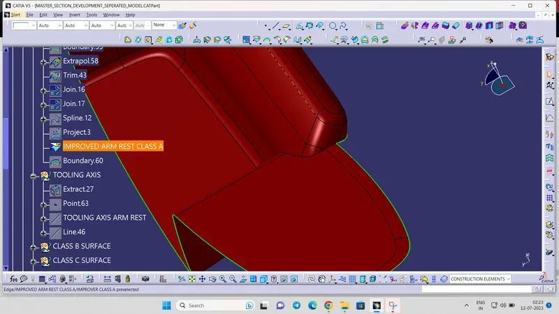
- Also the small fillet to be removed as it is a joint for a diffrent part
 \
\
2.TOOLING AXIS CREATION:
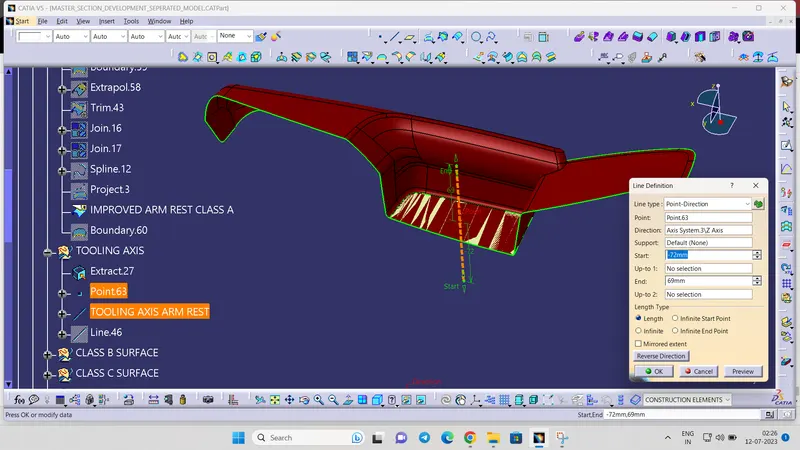
- For creating tooling axis i extracted an surface and created an point on that surface. aline created through that poin and check draft analysis.it satisfy so it considerd as main tooling axis.
3. DRAFT ANALYSIS OF CLASS A
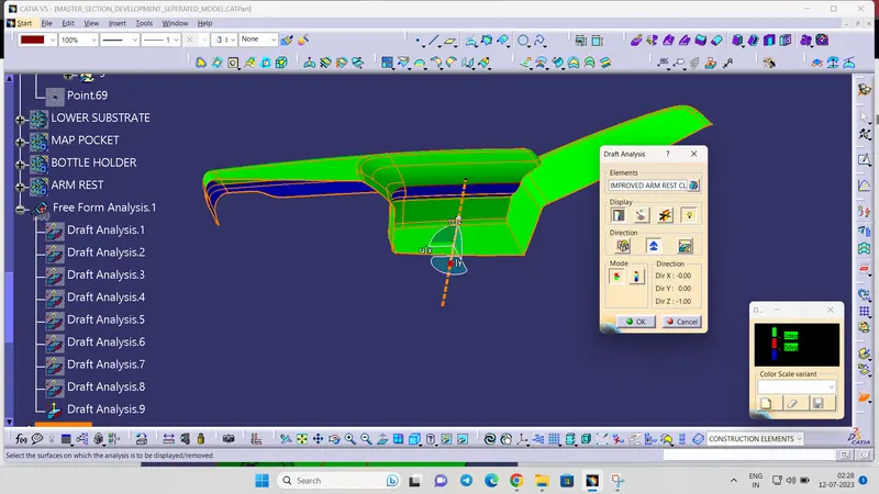
- We can notice that the A section needs to be re designed as the draft angle can not be satisfied.The design must be reverted to the Class A designer.or multiple tooling axis need to be generated
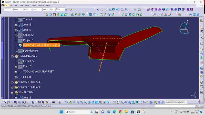
4.CLASS B SURFACE:
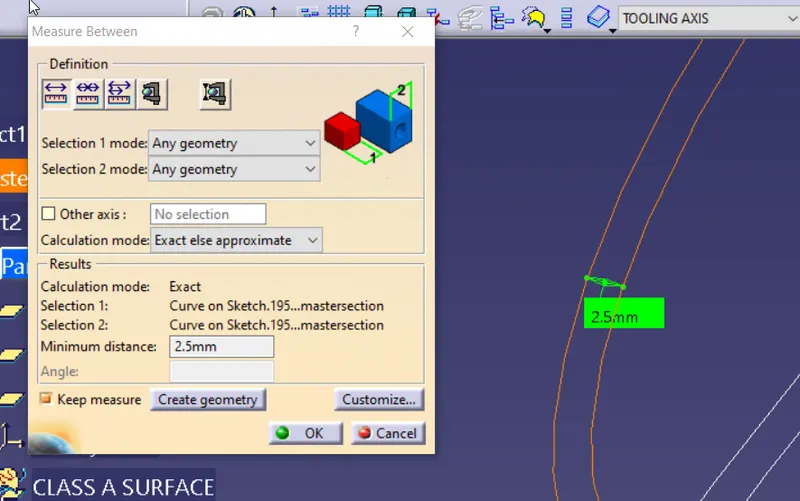
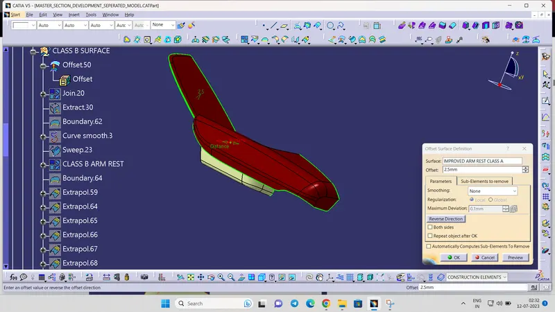
- Class b surface is created by offseting 2.5mm
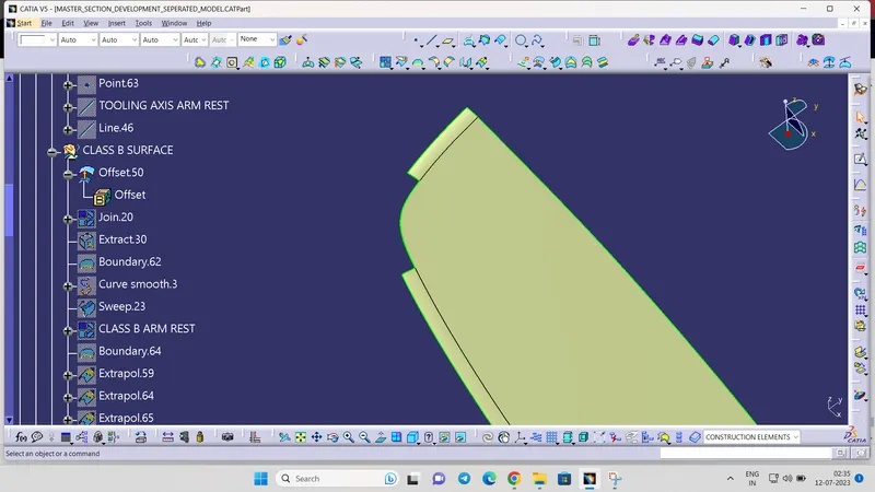
- some patch is foung ,solve the patch by sweep command.
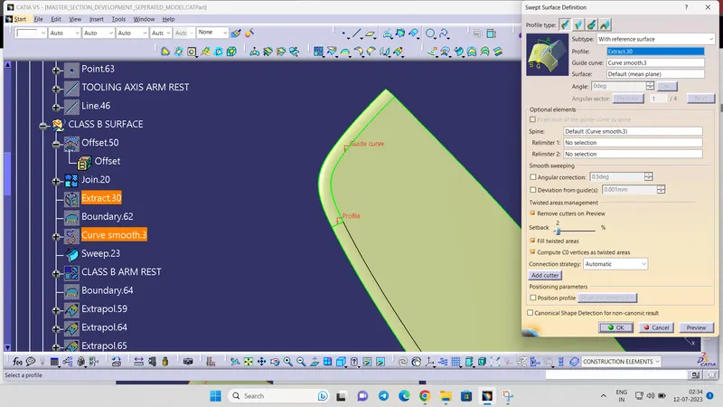
5.CLASS C SURFACE:
- The A and B surfaces are connected by another single surface which is called the C surface
- Class c is created using sweep command
- Here the sweep done in draft ditection and with reference to the surface.
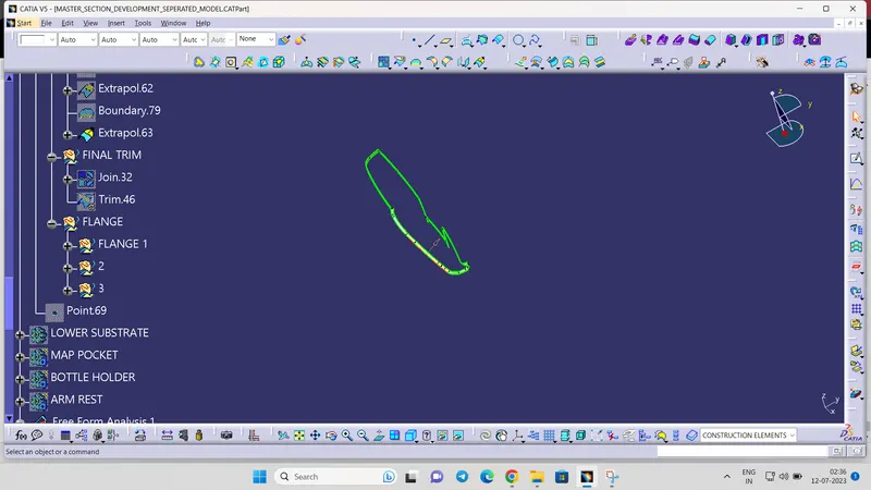
6. CLOSED SURFACE CREATION
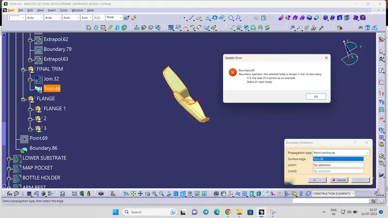
- Using the closed surface solid body is created.
7.FLANGE CREATION.
- Flanges are created using the help of master section
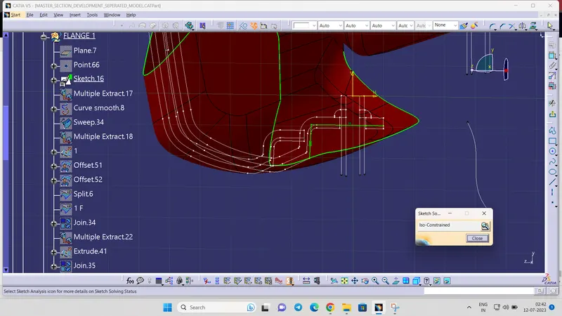
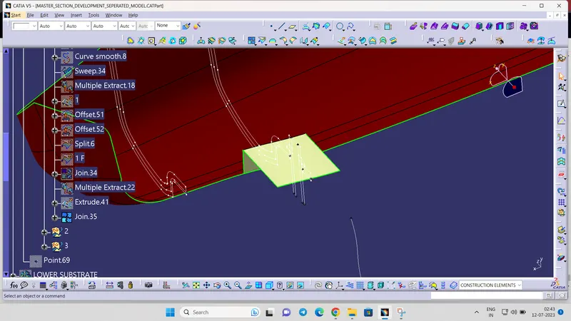
- similarly,
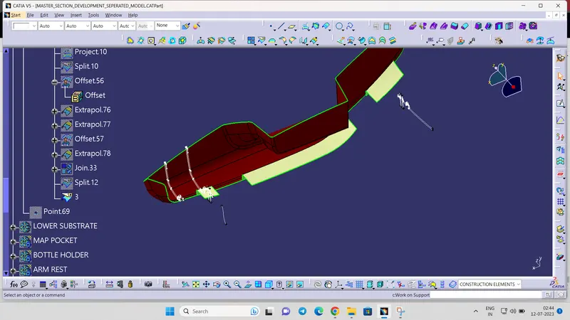
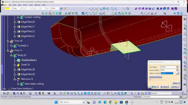
- thicken for an 2.5 mm
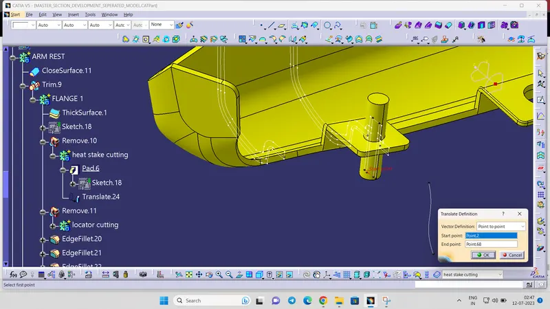
- using remove command with help of a padded cylinder a hole is created on the flange
8.DRAFT ANALSIS OF FINAL BODY.
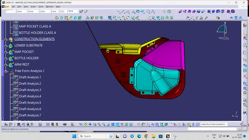
ALL THE PARTS ARE CREATED
PUSH PIN ASSEMBLY
- Here i created 2 dog house on lower substate .so i import two push pins
- The push pin axis and dog house axis constrained together
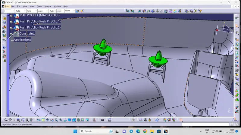
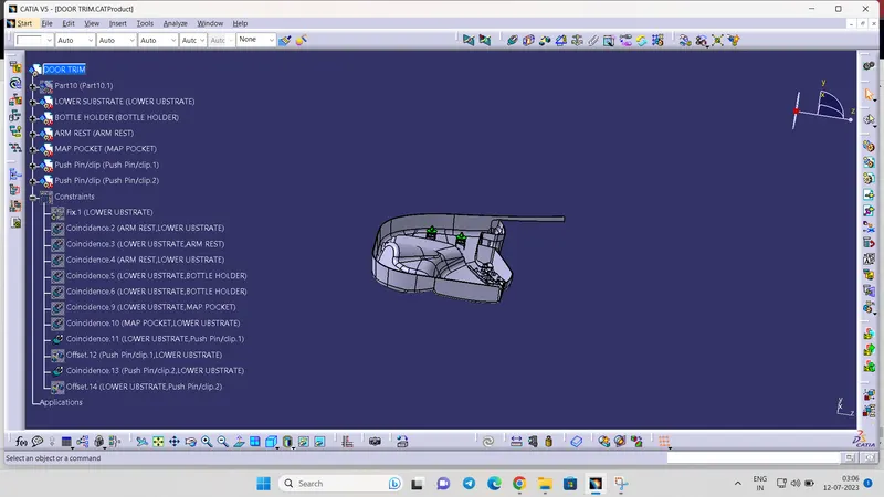
- final body with b side features
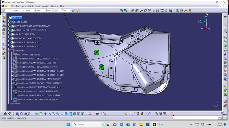
CONCLUSION:
The Design of The Automotive Door Trim Panel from a Class A surface to a Closed Part Body with all the necessary attachment features by following all the design rules using CATIA V5 is done Successfully and all the required CATPart and CATProduct files are attached.