Week 12- Final project
AIM
To Creation of Door trim panel model considering Class A surface, Nominal thickness and Attachment strategy.
OBJECTIVE
- Create thickened part using master section for reference
- Create the mounting features as per design guidelines in the industry and with master sections
- Apply material details :
- Draft analysis & Tooling analysis
- Creation of parting lines and check tooling feasibility
GENERAL RULES
- Surface check
- Tooling Axis
- Draft Analysis
- B Surface
- C Surface
- Final Output
- Create Engineering Features
- Create Dog House
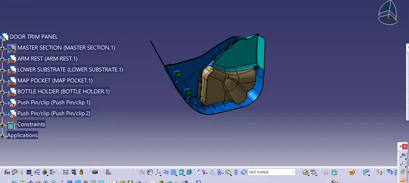
DOOR TRIM PANEL
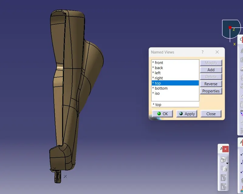
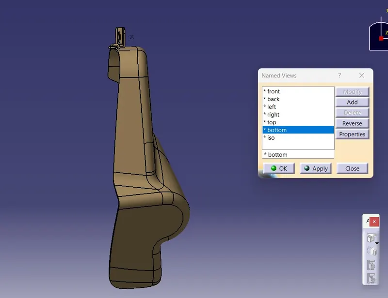
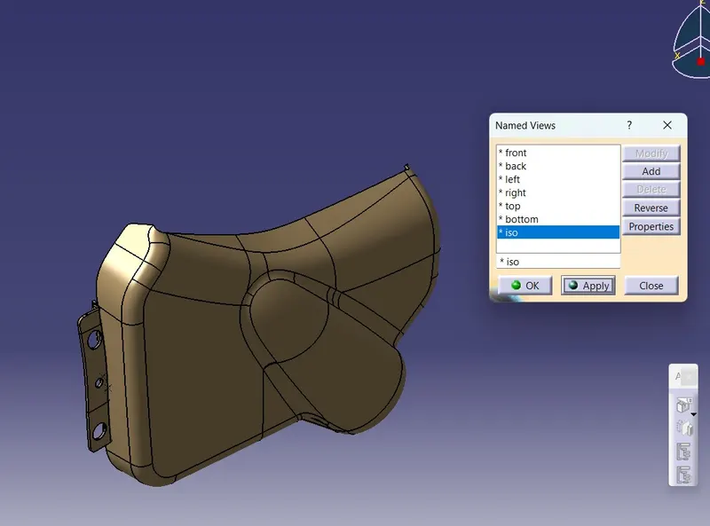
- ARM REST
- LOWER SUBSTRATE
- MAP POCKET
- BOTTLE HOLDER
ARM REST
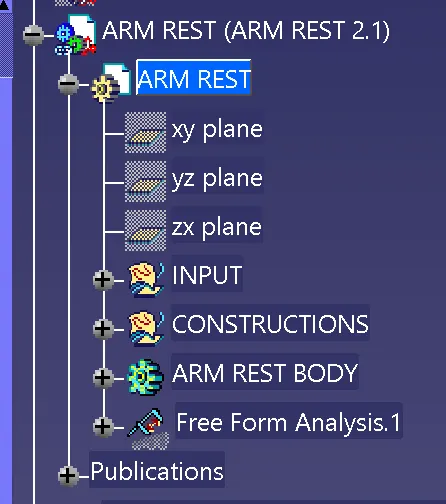
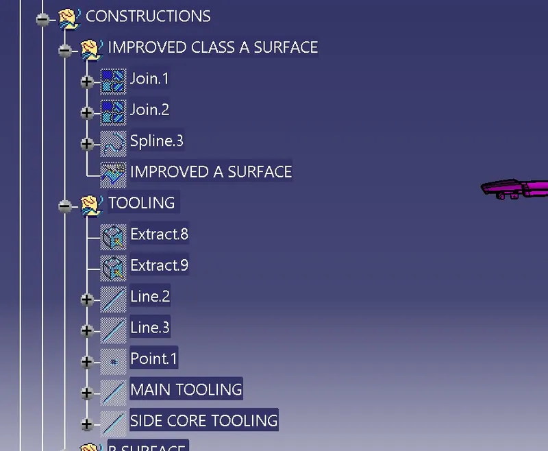
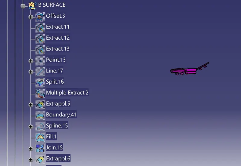
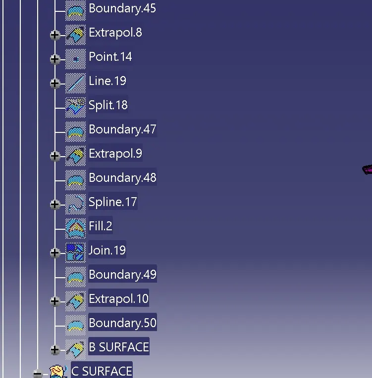
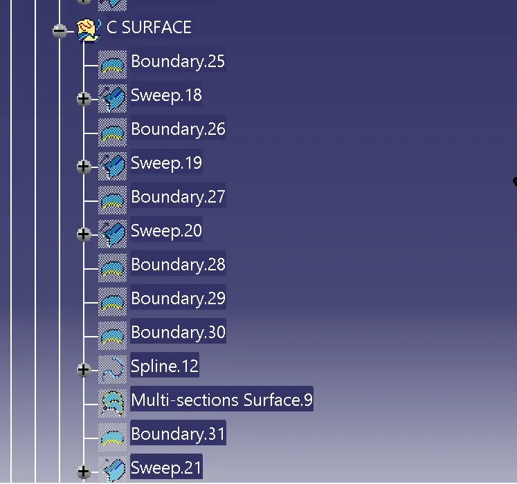
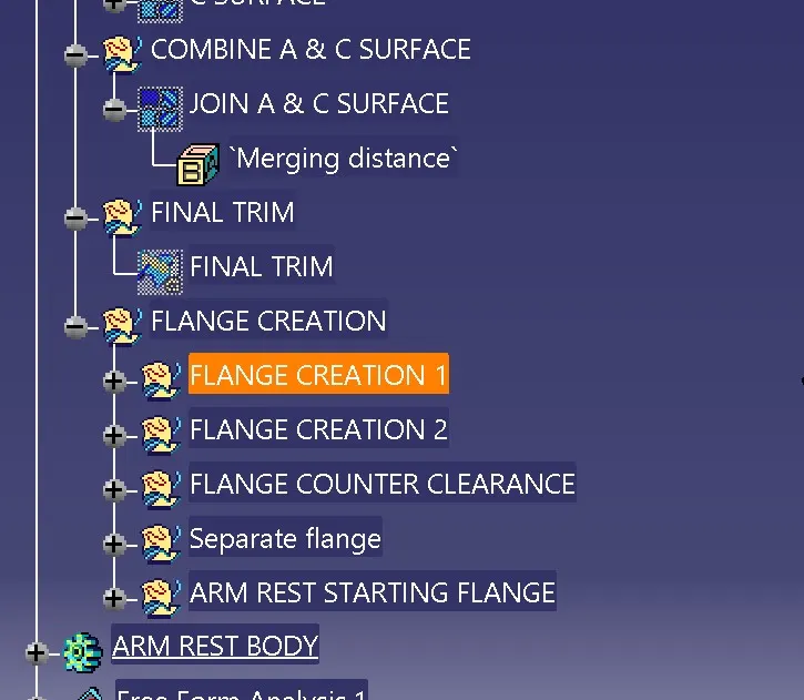
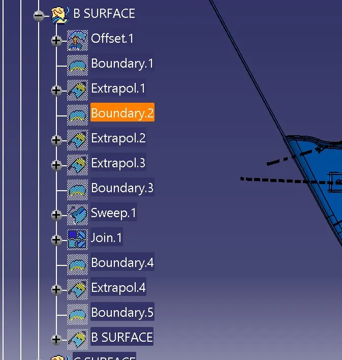
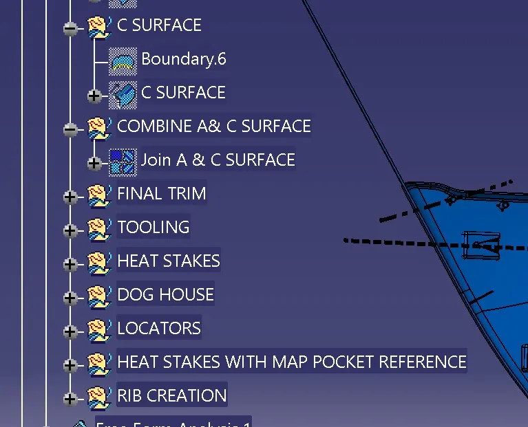
TREE STRUCTURE
WORKING PROCEDURE
- To Create a tooling direction and chect the draft its not clearing. we create the improved the Class A Surface.
- To create a B surface for using Improved A surface
- Improve A Surface to be offset in 2.5mm
- Some missing fillets need to be solve
- Extract the offset surface and extrapolate the extract surface
- Trim the extrapolate suirfaces
- B Surface to be created
- To create C surface for using A surface
- Create a Boundary
- After that using sweep for Draft as TOOLING DIRECTION
- Using SWEEP,EXTRAPOLATE,TRIM,SPLIT
- C Surface to be created
- Combine A Surface & C Surface by using JOIN
- Final output to be Trim the B surface & JOIN A&C
- Part body using Close surface for Final Trim
- To Create Enginerering Dog house as per Master section.
-
FLANGE CREATION
- To create a sketch for the reference master section and
- Extract the edge of the body
- Curve and Provile available so we using sweep with reference surface
- create the eXtrude and offset the the extrude
- And split the body for require
- After creation of flange DRAFT 0.5 degree and edge fillet also used at required dimension.
- NEED TO CLEAR 0.5MM CLEARANCE HOLE
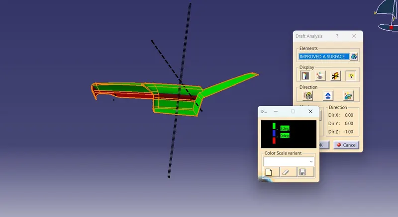
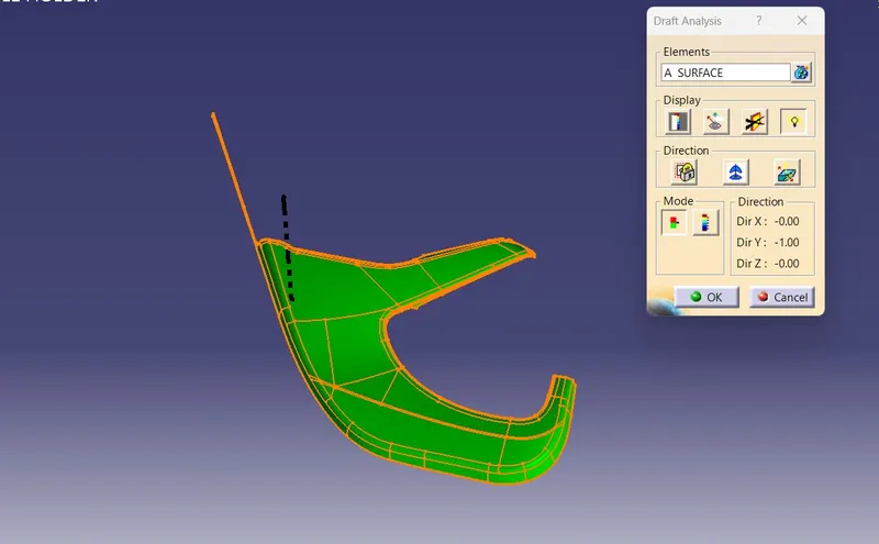
DRAFT ANALYSIS
IMPROVED CLASS A SURFACE (main tooling)
side tooling or core tooling
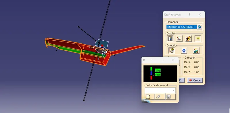
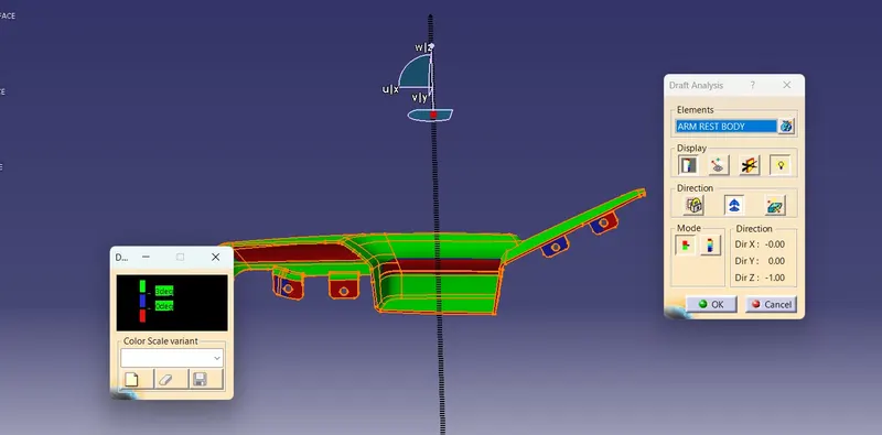
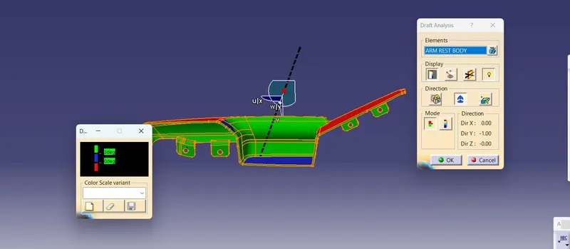
VIEW
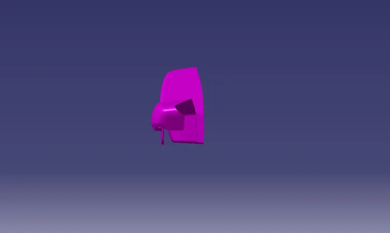
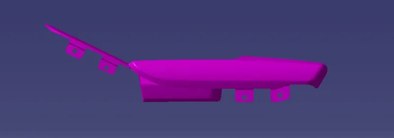
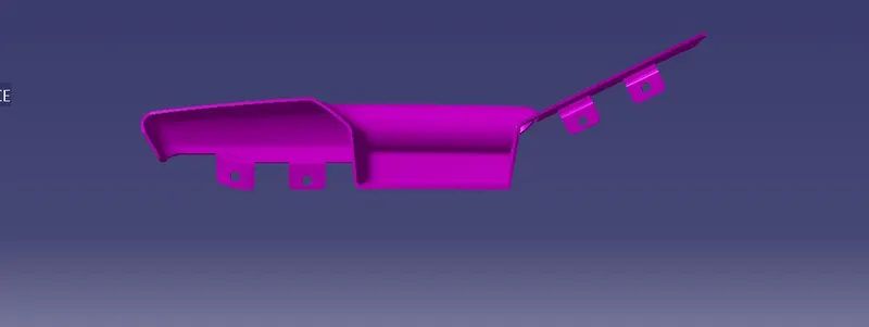
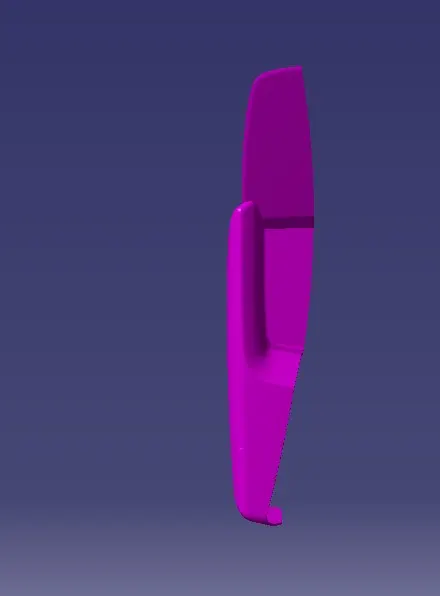
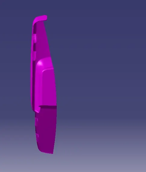
LOWER SUBSTRATE
WORKING PROCEDURE
- To Create a tooling direction and checK the draft.
- To create a B surface for using A surface
- Improve A Surface to be offset in 2.5mm
- Some missing fillets need to be solve
- Extract the offset surface and extrapolate the extract surface
- Trim the extrapolate suirfaces
- B Surface to be created
- To create C surface for using A surface
- Create a Boundary
- After that using sweep for Draft as TOOLING DIRECTION
- Using SWEEP,EXTRAPOLATE,TRIM,SPLIT
- C Surface to be created
- Combine A Surface & C Surface by using JOIN
- Final output to be Trim the B surface & JOIN A&C
- Part body using Close surface for Final Trim
- To Create Enginerering Dog house as per Master section.
-
HEAT STAKES CREATION
- To craete a centre point for given master section as reference
- Create a sketch and Extract the curvature of the edges
- offset the curve using parallel curve tool and create a Required Point using point repetion tool
- And also create a another sketch for Ribs
- Assemble the Rib with Heat stakes in Part body
- Copy the heat takes with Ribs and paste special with link to main body
- After that Translate the point to point
- Before that we need to Draft create 0.5 degree and 0.3 mm edge fillet
-
DOG HOUSE CREATION
- To create a datum plane and create a point
- create sketch using the master section for the reference
- After Pad that sketch and Assemble with main closed surface
- And also create a Ribs with the master section and Pad the sketch
- Union Trim the Dog house
- And also create a Bush Pin and Pad the sketch
- Finally Remove the bush pin with dog house.
RIB CREATION
- Create a point and isoLATE THE POINT COORDINATES
- Create a Curve and point repetion with proper distance
- and Create a Sketch Line and Extrude the line
- And thicken the extrude at 1mm
- Offset the surface and split the body
- After creation of Rib need to provide Draft at 0.5 degree and Edge fillet 0.125mm
- Copy the Rib and paste special and translate the point to point
TREE STRUCTURE
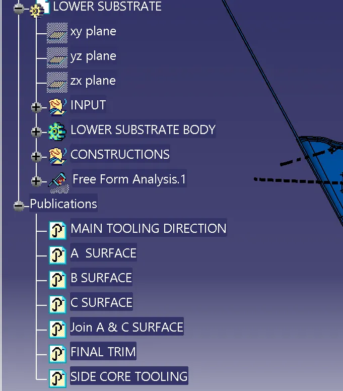
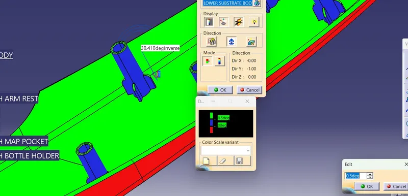
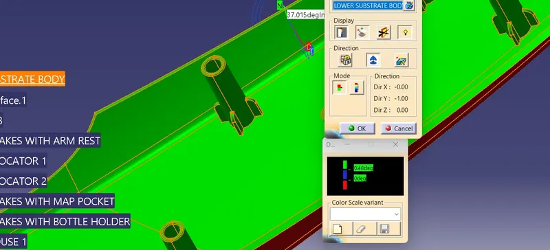
DRAFT ANALYSIS
A SURFACE
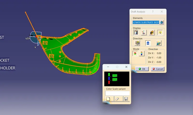
PART BODY
DOG HOUSE
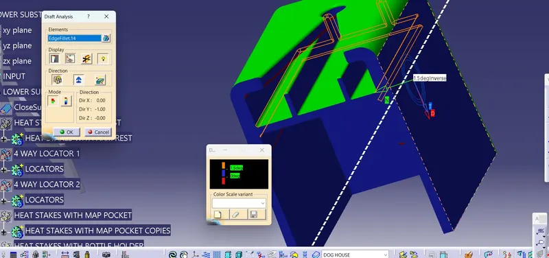
0.49 DRAFT CLEARED
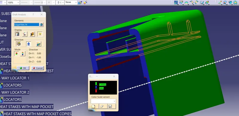
RIBS
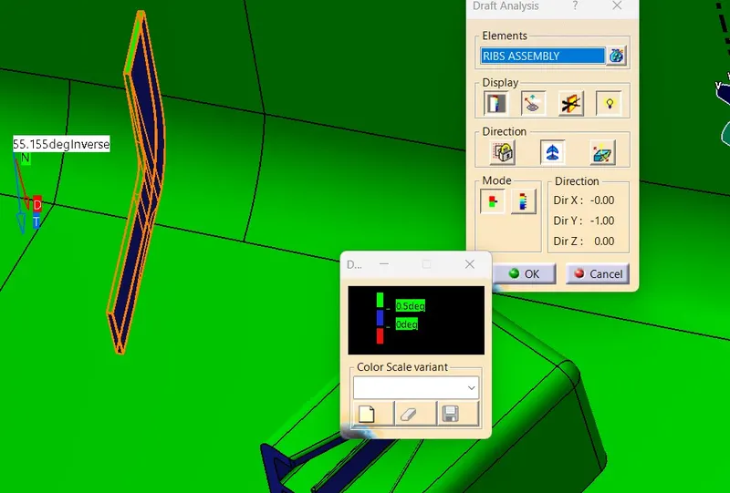
0.4 DEGREE DRAFT FULLY CLEARED
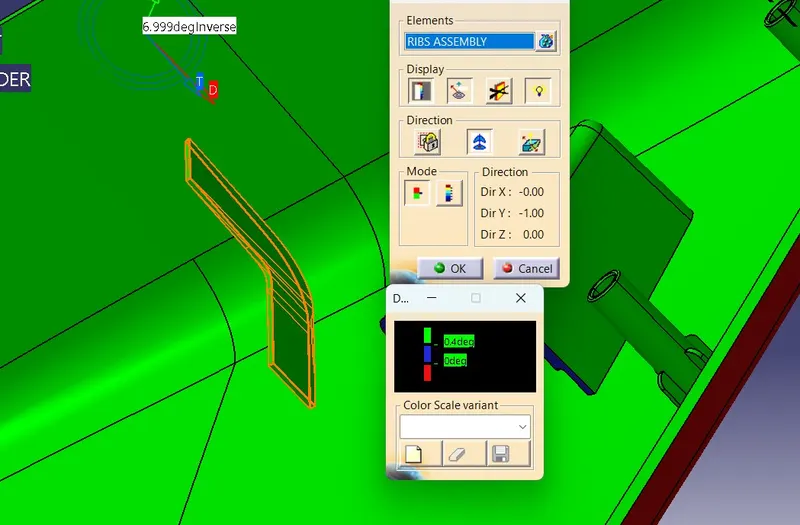
HEAT STAKES
VIEW
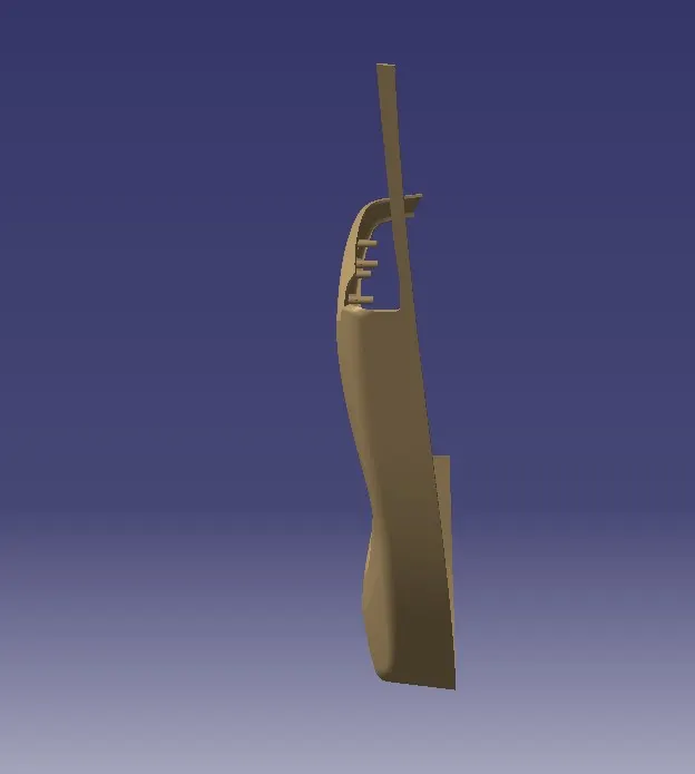
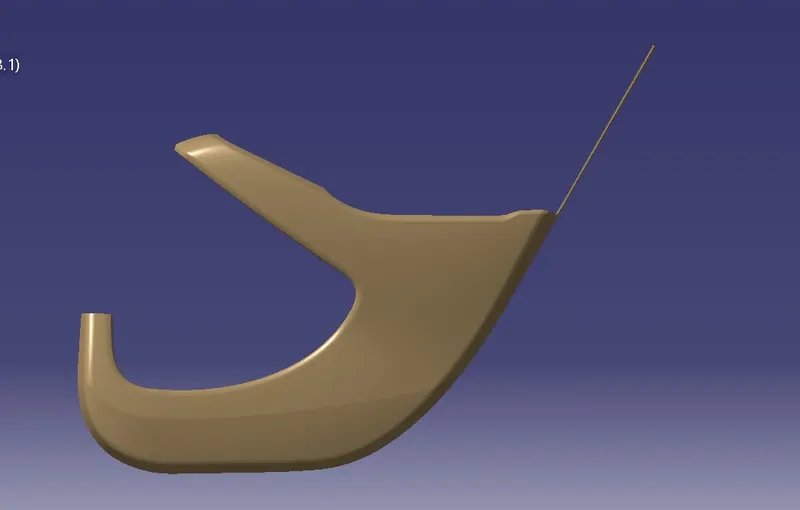
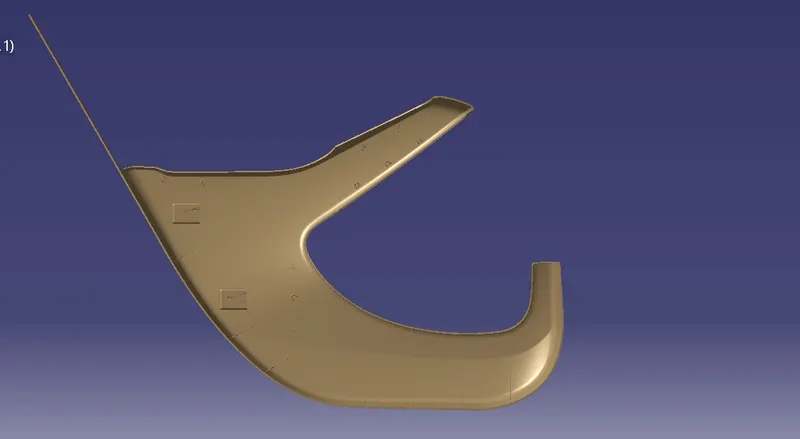
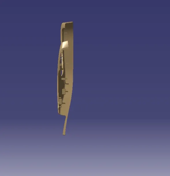
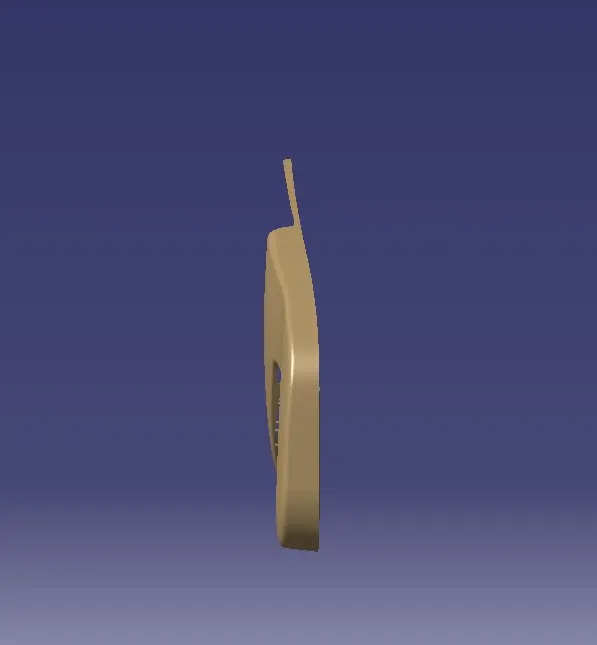
MAP POCKET
WORKING PROCEDURE
- To Create a tooling direction and checK the draft
- To create a B surface for using A surface
- Improve A Surface to be offset in 2.5mm
- Some missing fillets need to be solve
- Extract the offset surface and extrapolate the extract surface
- Trim the extrapolate suirfaces
- B Surface to be created
- To create C surface for using A surface
- Create a Boundary
- After that using sweep for Draft as TOOLING DIRECTION
- Using SWEEP,EXTRAPOLATE,TRIM,SPLIT
- C Surface to be created
- Combine A Surface & C Surface by using JOIN
- Final output to be Trim the B surface & JOIN A&C
- Part body using Close surface for Final Trim
- To Create Enginerering Dog house as per Master section.
-
FLANGE CREATION
- To create a sketch for the reference master section and
- Extract the edge of the body
- Curve and Provile available so we using sweep with reference surface
- create the eXtrude and offset the the extrude
- And split the body for require
- After creation of flange DRAFT 0.5 degree and edge fillet also used at required dimension.
- NEED TO CLEAR 0.5MM CLEARANCE HOLE
TREE STRUCTURE
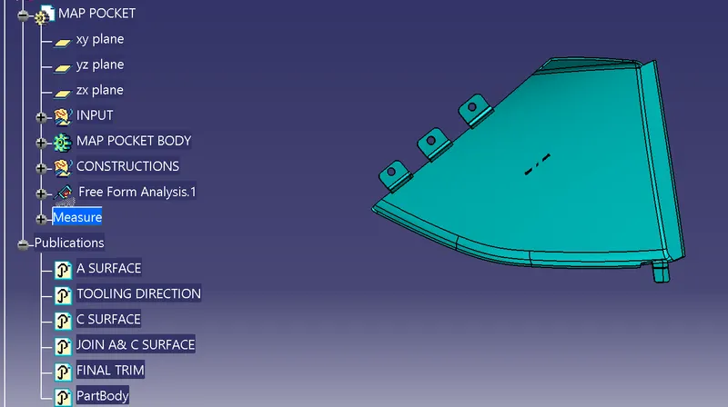
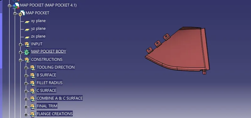
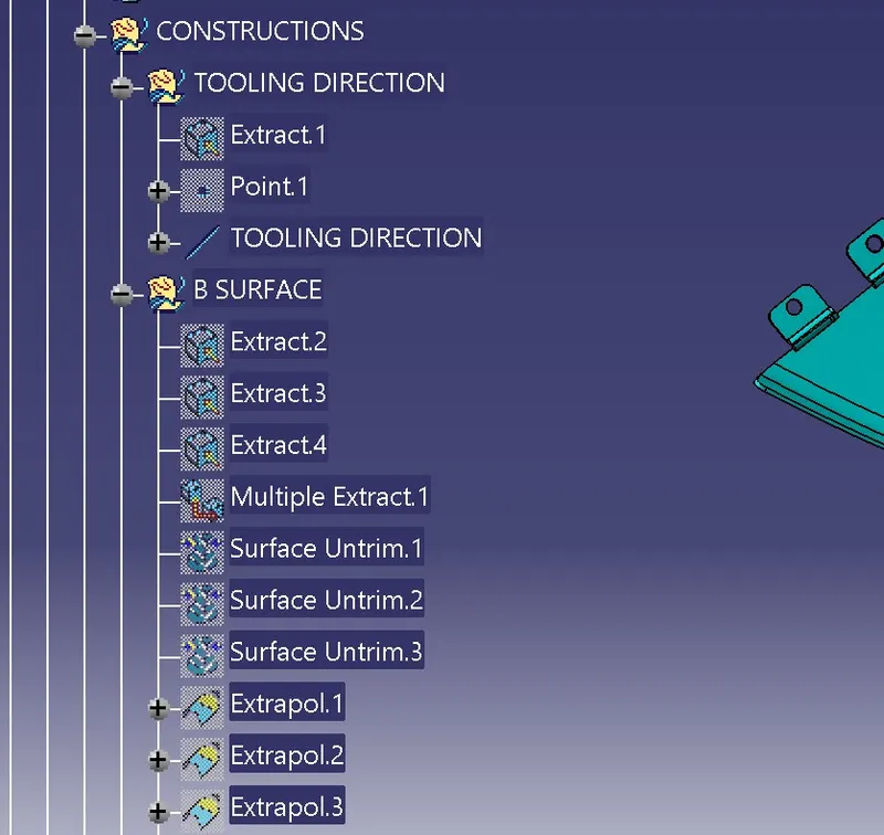
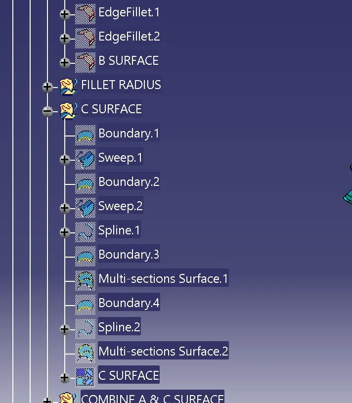
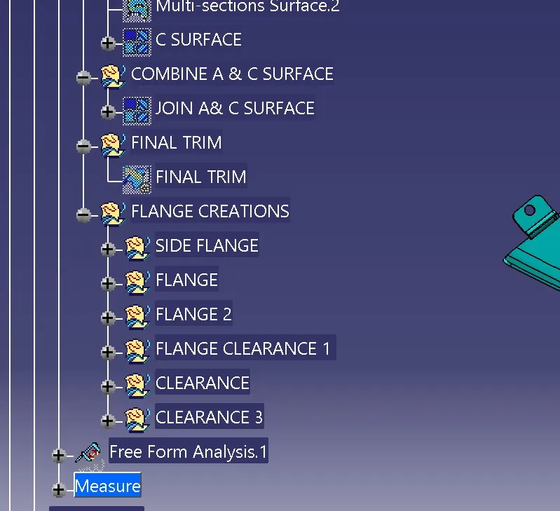
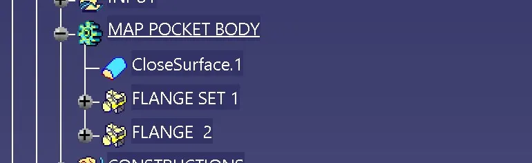
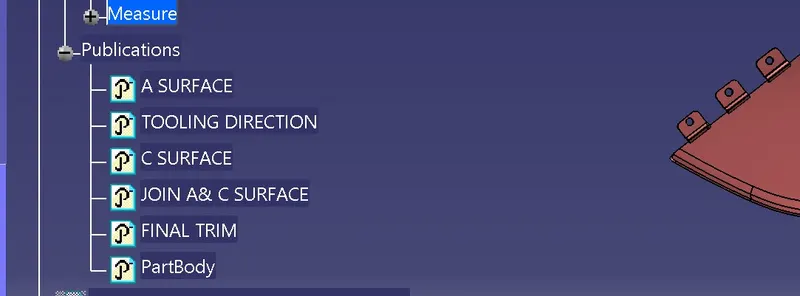
DRAFT ANALYSIS
A SURFACE
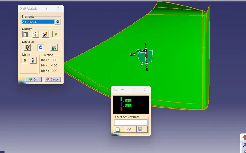
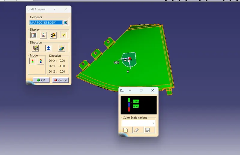
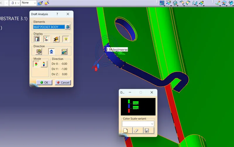
2.8 DEGREE DRAFT CLEARING FLANGE
VIEW
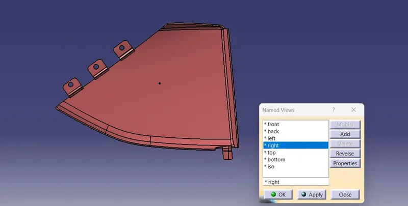
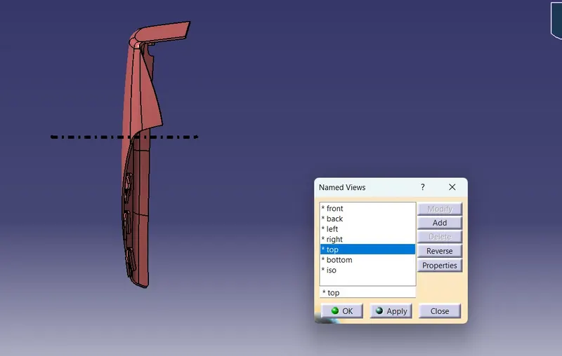
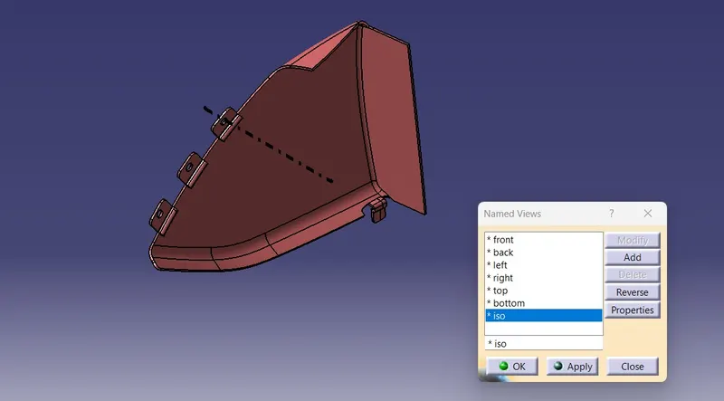
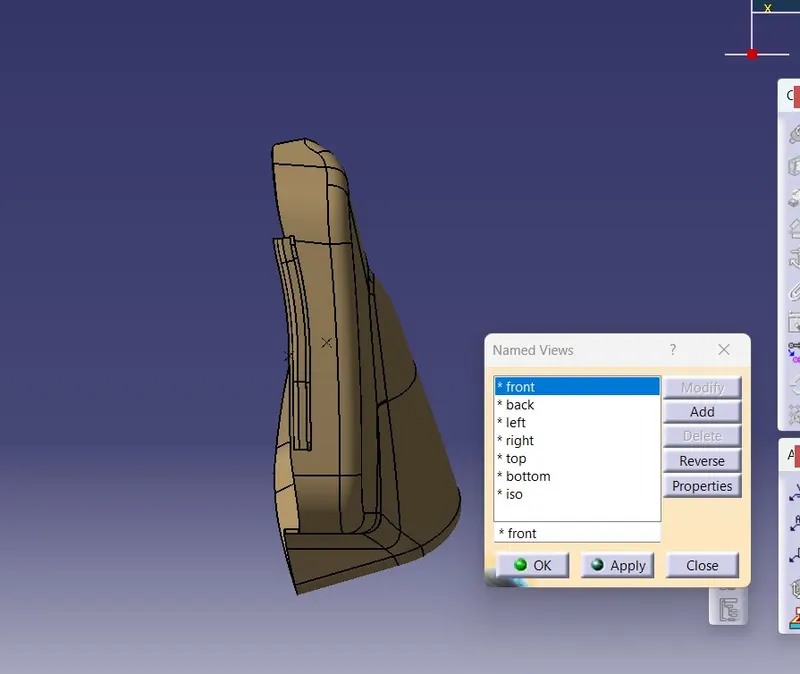
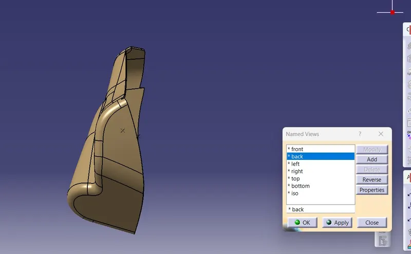
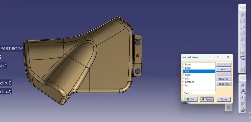
BOTTLE HOLDER
WORKING PROCEDURE
- To Create a tooling direction and checK the draft
- To create a B surface for using A surface
- Improve A Surface to be offset in 2.5mm
- Extract the offset surface and extrapolate the extract surface
- Trim the extrapolate suirfaces
- B Surface to be created
- To create C surface for using A surface
- Create a Boundary
- After that using sweep for Draft as TOOLING DIRECTION
- Using SWEEP,EXTRAPOLATE,TRIM,SPLIT
- C Surface to be created
- Combine A Surface & C Surface by using JOIN
- Final output to be Trim the B surface & JOIN A&C
- Part body using Close surface for Final Trim
- To Create Continue Flange With the Lower substrate as a refrenece.
-
FLANGE CREATION
- To create a sketch for the reference master section and
- Extract the edge of the body
- Curve and Provile available so we using sweep with reference surface
- create the eXtrude and offset the the extrude
- And split the body for require
- After creation of flange DRAFT 0.5 degree and edge fillet also used at required dimension.
- NEED TO CLEAR 0.5MM CLEARANCE HOLE for HEAT STAKES
- Need to create 0.1mm clearance for 4 WAY LOCATORS
TREE STRUCTURE
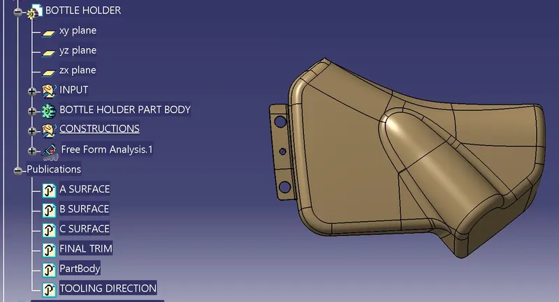
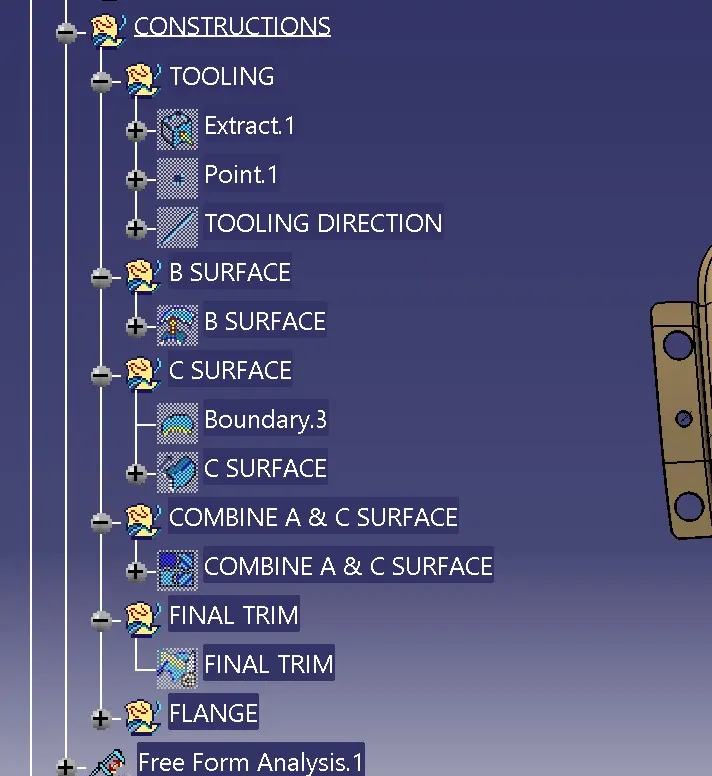
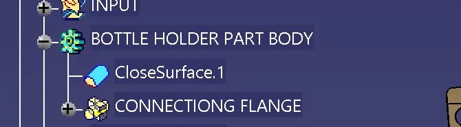
DRAFT ANALYSIS
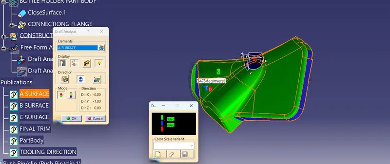
A SURFACE
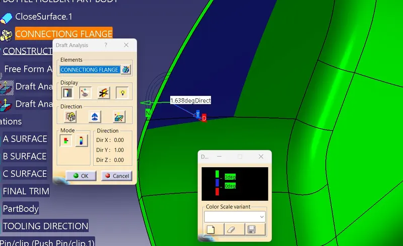
A surface not clearing the draft 3 degree
PART BODY
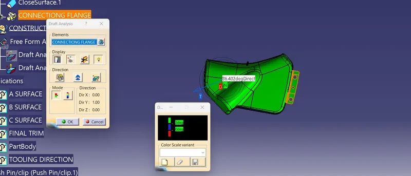
VIEW

DESIGN CONSIDERATION / RULES FOR ATTACHMENT FEATURES
RIB
Ribs provides a economical stiffness and strength in molded parts without increasing overall wall thickness
- Draft angle - 0.5 degree
- Thickness - 0.4 * t
- Height - 5 * t
- Spacing
- Thickness at Top -0.75mm
- Optional Radius - 0.75 mm
DOG HOUSE
thickness of the part to be 2.5 mm.
"C" is where the doghouse contacts the backside of the surface
-
Doghouse wall thickness at the intersection of the part wall ( C ) should be 40% or less than the main wall stock ( T ).
-
The height of ( B ) should be between 3.0 – 6.0 mm
Draft 1.5 degree
LOCATORS
A Working Part is free in space can move in an infinite number of directions. For analysis, this motion can be broken down into 12 directional movements or "degrees of freedom". All 12 degrees of freedom must be restricted to ensure proper referencing of a work-piece. It is also known as 3-2-1 Principle
Draft 0.5 degree
HEAT STAKES
Heat Stakes is the process to attach two separate components together by melting Plastic Material into a desired shape that will holds Secondary components.
Advantages
- Multiple fastening points
- Reduced cost of machinery
- Simplification of machinery
Draft 0.5 degree
DOOR TRIM PANEL
RESULT
Thus, the Door trim panel model considering Class A surface, Nominal thickness and Attachment strategy to be created and DRAFT analalysis report attached Power Point Representation.