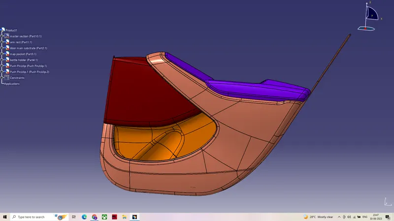
Week 12- Final project
AIM :- To Develop the given Door Trim panel considering the design rules .
Procedure
- Creating a tooling axis from the given class A surface using bisection method and analysing the given class a surface.
- Creating class B and c surfaces from the class A surface & tooling axis with a draft angle of 3 degrees using sweep.
- Joining the class A and C surfaces and timmed with the B surface to form the closed surface .
- From the closed surface by using thickness we can get a solid body in part workbench.
- Creating the Dog House ,Heat stakes and four way locators for the Door Trim panel considering the design rules
GIVEN DOOR TRIM PANEL CONSISTS OF FOUR SUB ELEMENTS WITHA MASTERSECTION
1.Arm rest
2.Door main substrate
3.Map pocket
4.Bottle holder
ARM REST
Given class A surface of the arm rest been inspected visually using boundary for any missing surfaces fillets or patches . After inspecting
the class A surface it was found there was a uneven surface which been modified using muliple extraxt and extrude then joined using join so
that we can improve the quality of the class A surface.
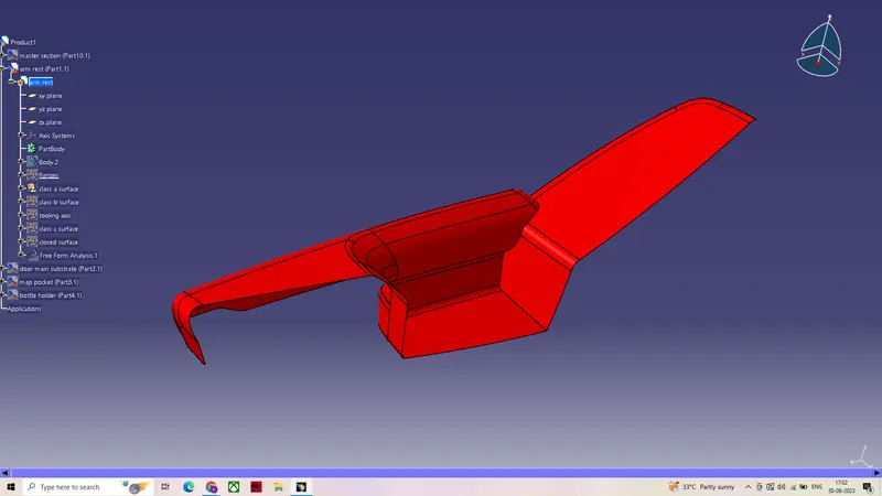
Creating a tooling axis from the given class A surface using bisection method and analysingthe given class a surface.
- After visual inspection of the class A surface we can conclude that Y axis would be the best possible way to create the tooling axis.
- creating a intersecting line from the class A surface so that we can find the surfaces parallel to dummy tool which may create problem.
- After performing draft analysis it was found that the region in blue had a negative draft which cannot be cleared using a single axis.
- Hence side core axis also been developed with respect to mastersection.
MAIN TOOLING AXIS
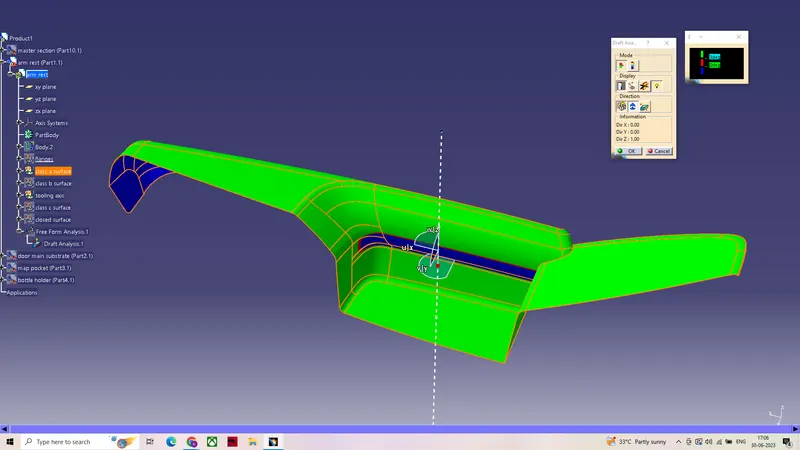
SIDE CORE AXIS
Creating class B and class C surfaces .
- Extracting the surfaces from the class A surface using extract then offsetted to form a thickness of 2.5mm .
- The obtained class B surface further modified and added fillet.
- To create a class C surface , boundary of the class A surface extracted using boundary command.
- By using boundary of the class A surface and the tooling axis as refrence class C surface extracted using sweep command
To create a closed thick surface the obtained calss c and a surfaces been trimmed using class B surface.
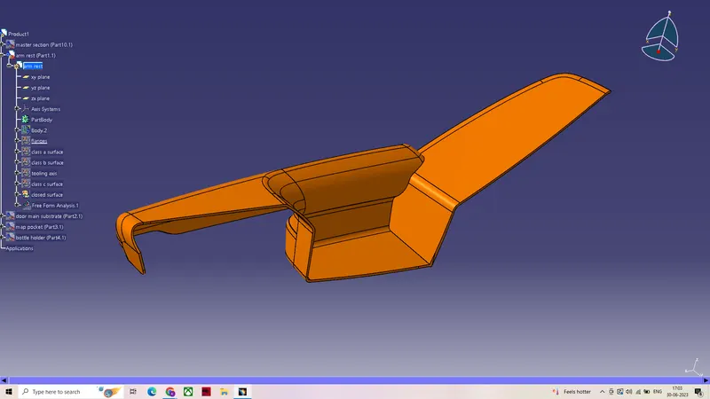
The obtained closed body then thickened in the part work bench to form a solid.
FLANGES
Flanges are developed with the refrence of master section and further modified using fillets (given a draft of 0.5 degrees).
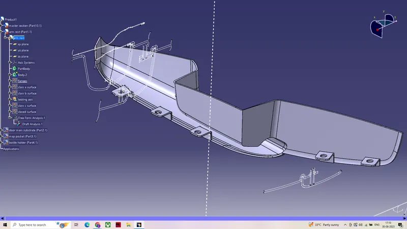
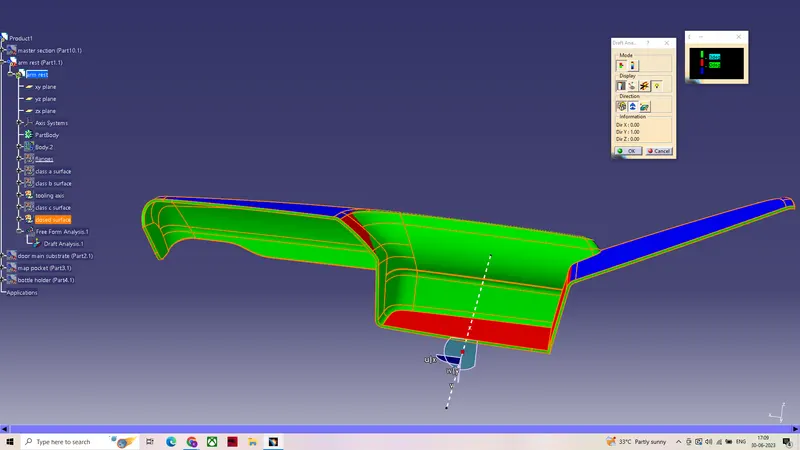
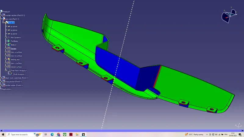
Draft analysis on the solid surface with respect to side core axis.
- First by setting the view parameters to material we can further proceed to draft analysis , after positioning the compass on the tooling axis we can get the draft anlysis.(min draft required for the component is set to 3 degrees)
- Green region in the draft analysis indicates that the component has a minimum draft of 3 degrees.
- Region in red indicates a minimum draft of 0.45 degrees.
- Blue region indicates no draft or negative draft.
- which maens the component cannot be manfacturable or it will create problems while manfacturing.
DOOR MAIN SUBSTRATE
Quality of the given class A surface been inspected visually to ensure it had a better quality.
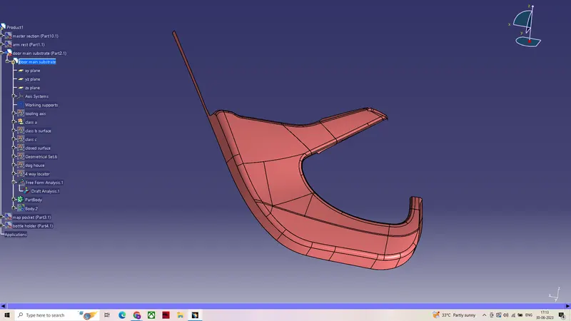
Toolingaxis created for the door main substrate by taking the refrence of mastersection.
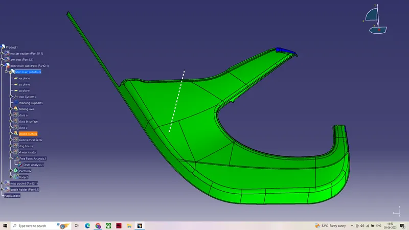
After developing the closed surface from the class A surface it was further performed draft analsys .
- Green region in the draft analysis indicates that the component has a minimum draft of 3 degrees.
- Blue region indicates no draft or negative draft.
FOUR WAY LOCATORS
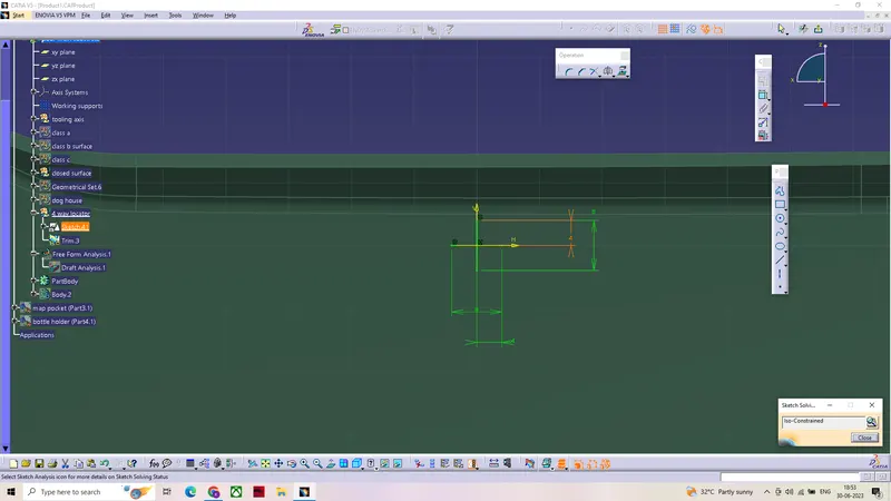
To develop the part body of a four way locator sketching must be done in sketcher workbench.
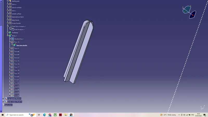
After obtaining a pad from the sketch it was further modified by applying fillets , chamfer etc (a draft of 0.5 degrees given to the part body)
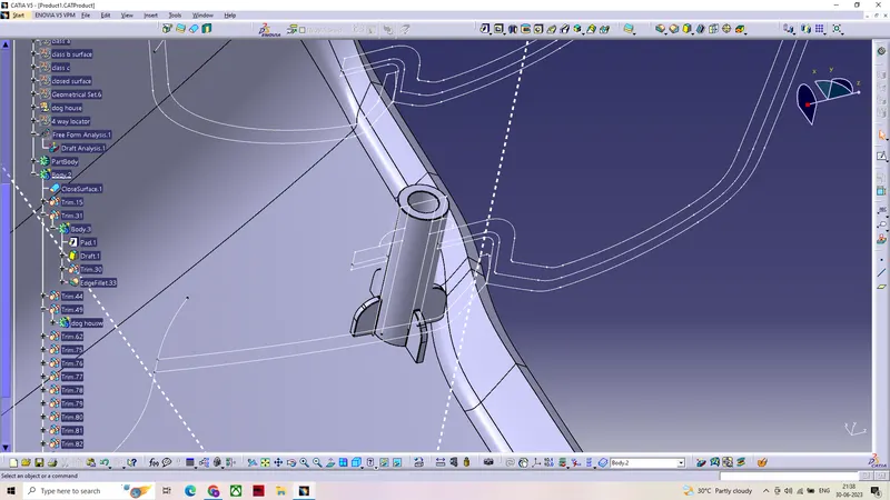
DOG HOUSE
- Sketching been done to extract dog house surface with the specified rules.
- After extruding the surface from the sketch using extrude (draft of 1.5 degrees) , it was further modified by using trim and fillets.
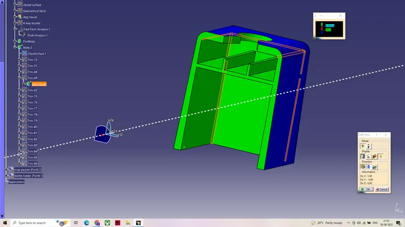
The house further performed draft analysis with respect to side core axis.
- Green region indicates a minimum draft of 0.45 degrees.
- Region in blue indicates no draft or negative draft.
HEAT STAKES
Heat stakes were are developed with the refrence of master section and further modified using fillets (given a draft of 0.5 degrees).
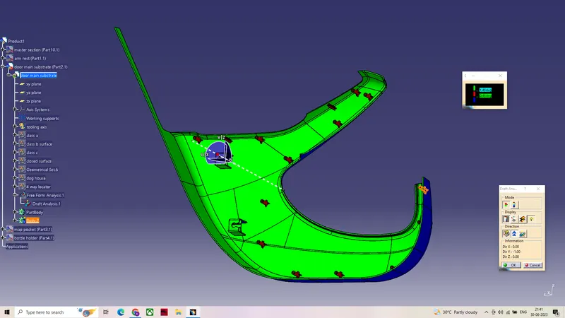
DRAFT ANSLYSIS PERFORMED ON THE DOOR MAIN SUBSTRATE WITH RESPECT TO MAIN TOOLING AXIS
- Green region in the draft analysis indicates that the component has a minimum draft of 1.45 degrees.
- Region in red indicates a minimum draft of 0.45 degrees.
- Blue region indicates no draft or negative draft.
- which maens the component cannot be manfacturable or it will create problems while manfacturing.
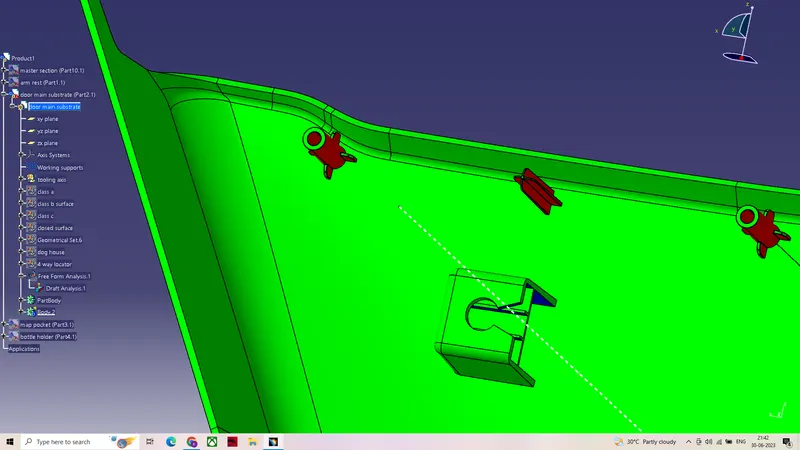
DOOR MAIN SUBSTRATE FINAL OUTPUT
MAP POCKET
Quality of the given class A surface been inspected visually to ensure it had a better quality.
And further proceeded to develop closed surface , with the obtained closed surface draft analysis performed with the main tooling axis.
- Green region in the draft analysis indicates that the component has a minimum draft of 3 degrees.
- Blue region indicates no draft or negative draft.
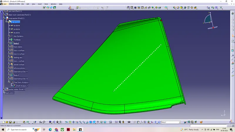
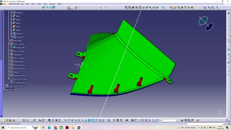
After adding heat stakes and fanges to the map pocket with respect to master section ,draft analsys performed on the whole body.
- Green region in the draft analysis indicates that the component has a minimum draft of 1.45 degrees.
- Region in red indicates a minimum draft of 0.45 degrees.
- Blue region indicates no draft or negative draft.
- which maens the component cannot be manfacturable or it will create problems while manfacturing.
BOTTLE HOLDER
Quality of the given class A surface been inspected visually to ensure it had a better quality.
TOOLING AXIS
Tooling axis been developed using bisection method,by creating a intersection on the class A surface so that we can find the surfaces parallel to dummy tool which may create problem.
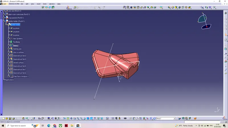
DRAFT ANALYSIS OF MAP POCKET CLASS A WITH RESPECT TO MAIN TOOLING AXIS
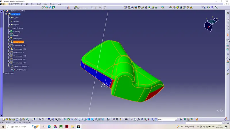
The region in red indicates a draft of 3 degrees ,while the region in blue indicates negative draft .
After performing several draft analsys with different axis , it was concluded that the class A surface should be modified to get better quality
output.
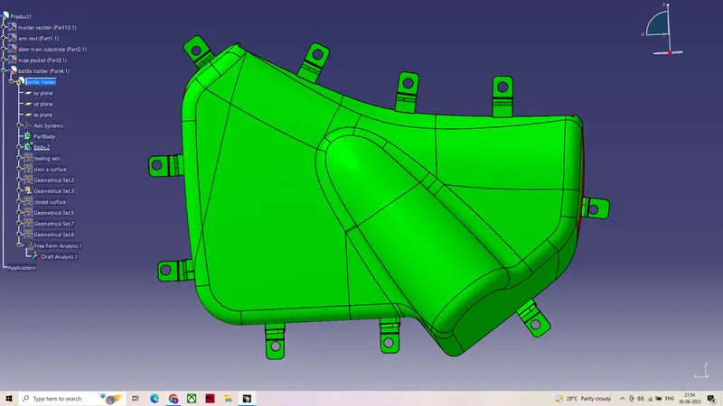
After adding fanges to the bottle holder with respect to master section ,draft analsys performed on the whole body.
- Green region in the draft analysis indicates that the component has a minimum draft of 1.45 degrees.
- Region in red indicates a minimum draft of 0.45 degrees.
- Blue region indicates no draft or negative draft.
- which maens the component cannot be manfacturable or it will create problems while manfacturing.
Door trim panel with engineering features
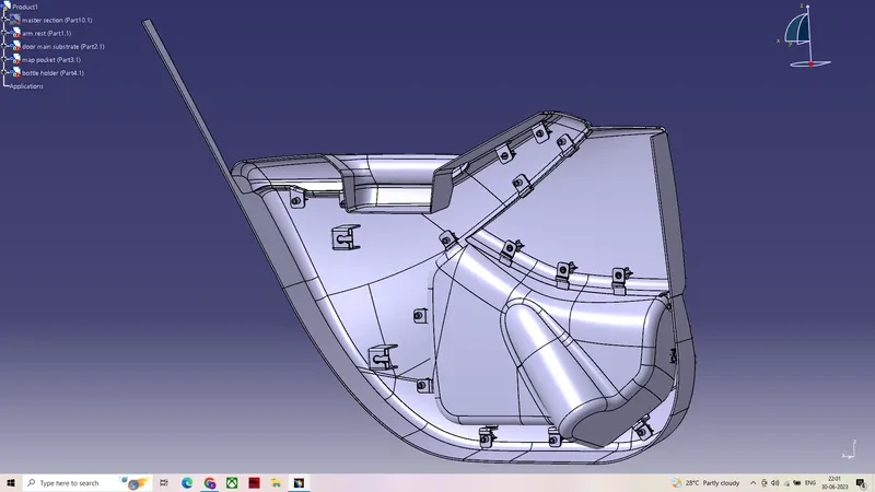
RIGHT VIEW OF DOOR TRIM PANEL

PUSH PINS WERE ASSEMBLED IN THE ASSEMBLY WORKBENCH TO THE DOOR TRIM PANEL DOG HOUSE
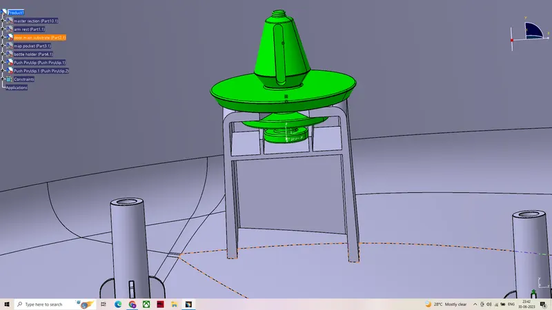
RIGHT VIEW OF FULLY ASSEMBLED DOOR TRIM PANEL WITH PUSH PINS
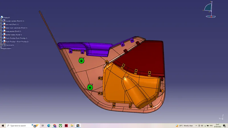
LEFT VIEW OF DOOR TRIM PANEL