Week 9 - Challenge 2 - Switch Bezel Design
AIM- To Create the SWITCH BEZEL component through the given Class-A surface.
Procedure
- Creating a tooling axis from the given class a surface using bisection method and analysing the given class a surface.
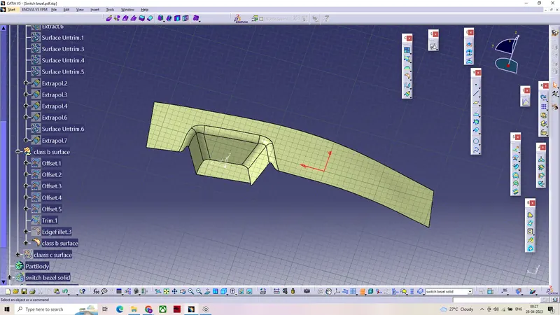
- Creating a class b surface from the given class A surface and off setting it to form a thickness of 2.5mm.
- Creating class c surface from the bondary of class A surface and tooling axis with a draft angle of 3 degrees using sweep.
- Joining the class A and C surfaces and timmed with the B surface to form the closed surface .
- From the closed surface by using thickness we can get a solid body in part workbench.
- Draft analysing the obatined final out put.
Creating a tooling axis from the given class A surface using bisection method and analysing the given class a surface.
After visual inspection of the class A surface we can conclude that z axis would be the best possible way to create the tooling axis.
creating a intersecting line from the class A surface so that we can find the surfaces parallel to dummy tool which may create problem.
lines are extended from the points of the intersection which may create a problem while manfacturing
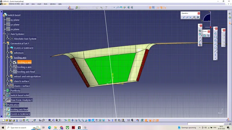
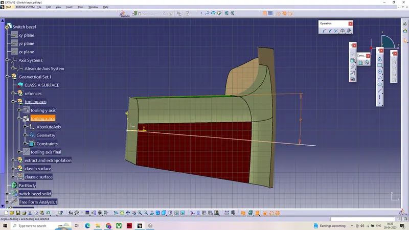
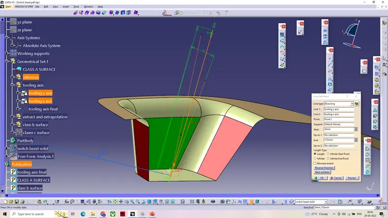
By using bisecting line the two parallel lines were bisected to form a tooling axis,and analysed it using draft analysis.
Creating a class B surface.
Extracting the surfaces from the class A surface using extract then apllied untrim and further extrapolated
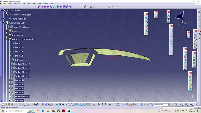
The extrapolated surfaces trimmed, then applied offset to form a thickness of 2.5mm .
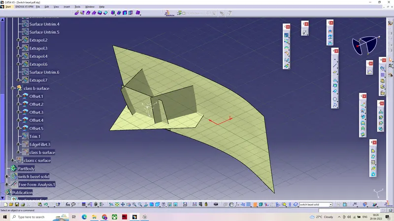
The obtained class B surface further modified using fillet
Creating class C surface .
To create a class C surface ,boundary of the class A surface extracted using boundary command
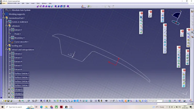
By using boundary of the class A surface and the tooling axis as refrence class C surface extracted using sweep command
class A and C surfaces joined together using join command
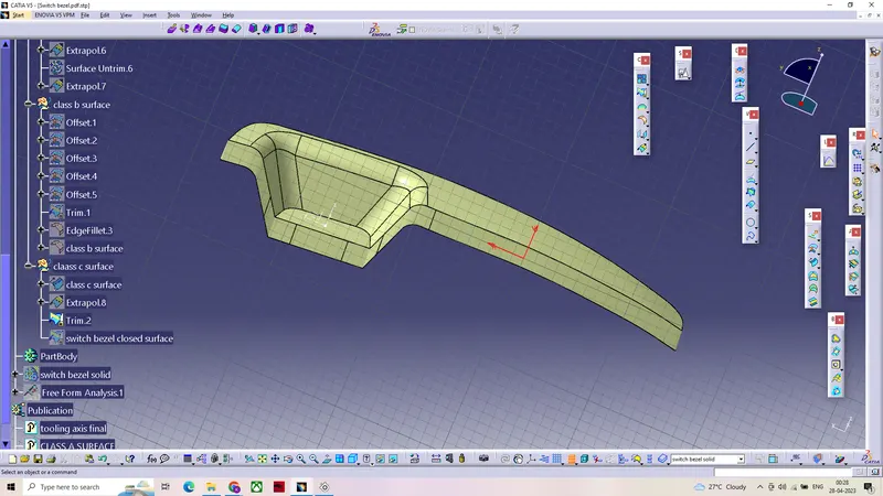
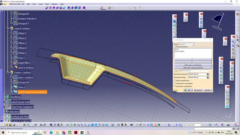
To create a closed thick surface the obtained surface been trimmed using class B surface.
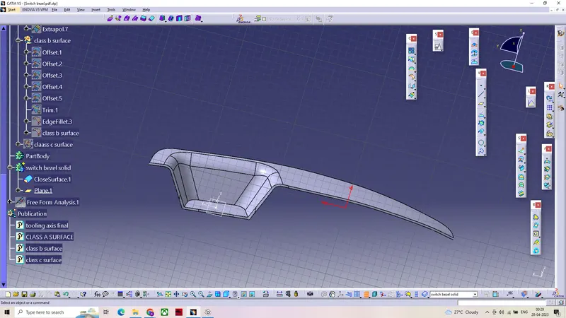
The obtained closed body then thickened in the part work bench to form a solid.
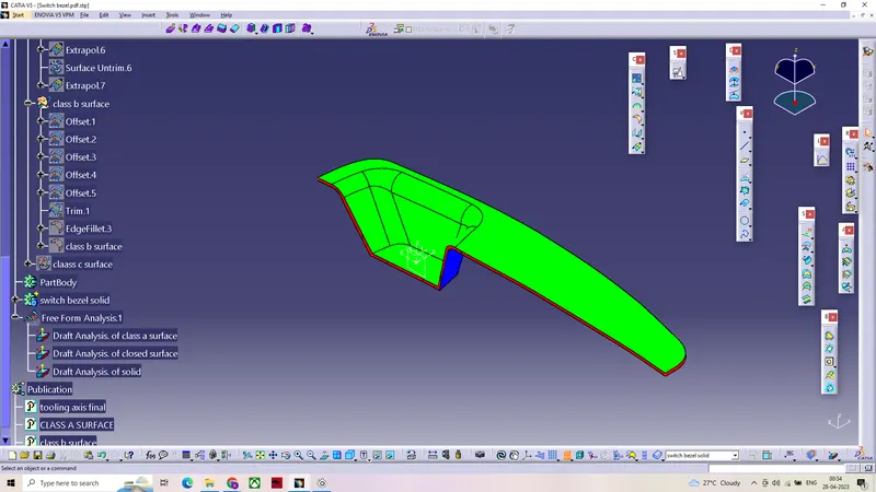
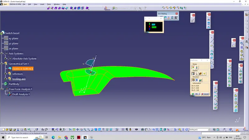
Draft analysis on the solid surface.
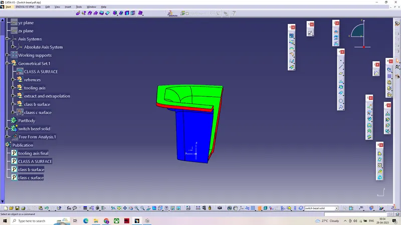
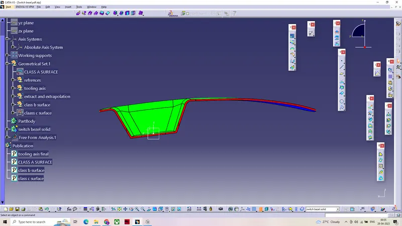
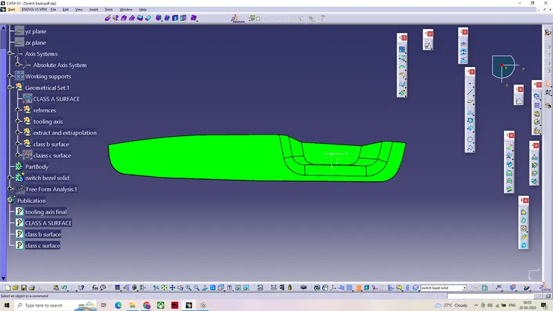
- First by setting the view parameters to material we can further proceed to draft analysis , after positioning the compass on the tooling axis we can get the draft anlysis.(min draft required for the component is set to 3mm)
- Green region in the draft analysis indicates that the component has a minimum draft of 3mm
- Blue region indicates no draft or negative draft.
- which maens the component cannot be manfacturable or it will create problems while manfacturing.
FRONT VIEW
SIDE VIEW
TOP VIEW
ISOMETRIC VIEW