Week 7 Challenge - Assembly Workbench
Quick Return Mechanism - Part creation and Assembly
AIM- Creation of parts with proper dimension and required Assumptions with Proper assembly constraints.
Procedure
- Creating 2D Sketches in CATIA while following the necessary guidelines.
- Then Creating the Solid CATparts from 2D sketches using pad and Boolean operations.
- The created parts are inserted or copied into assembly workbench.
- So that assembly can be done, By using constrains (contact, surface, offset) on reference (axis,points or planes)of the parts .
- Creating draft from the obtained assembly and its parts as specifies.
The given model consists of 5 parts.
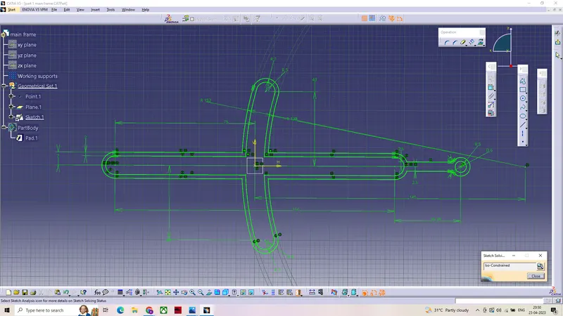
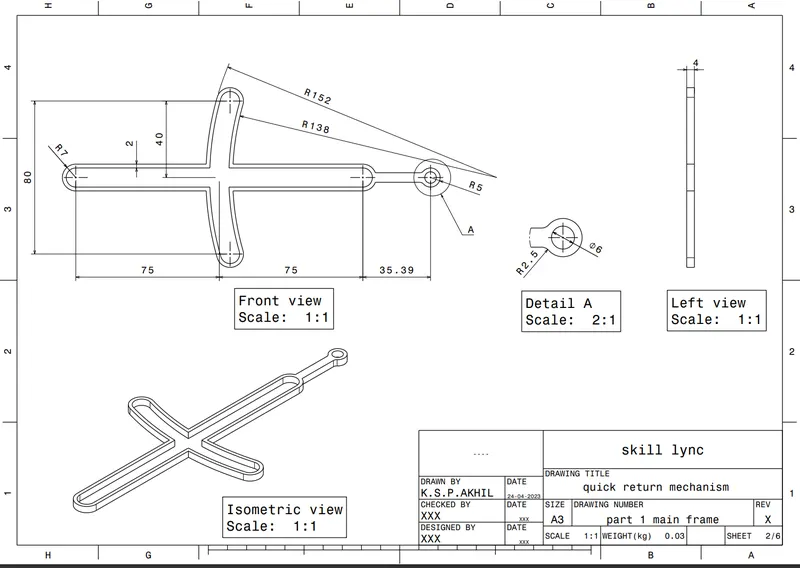
SKETCH OF THE MAIN FRAME
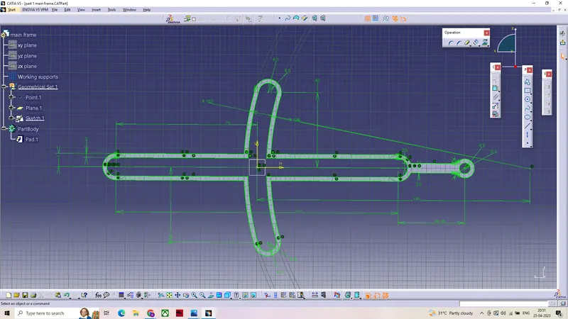
OBTAINED PAD FRM THE SKETCH
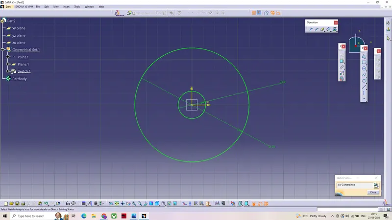
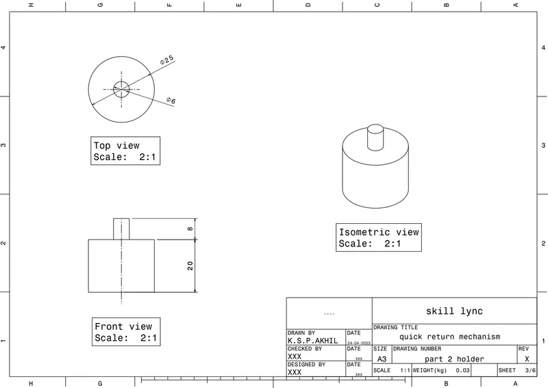
SKETCH OF THE PART 2 SUPPORT
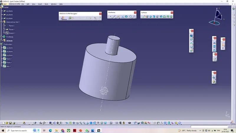
MULTIPAD FROM THE SKETCH
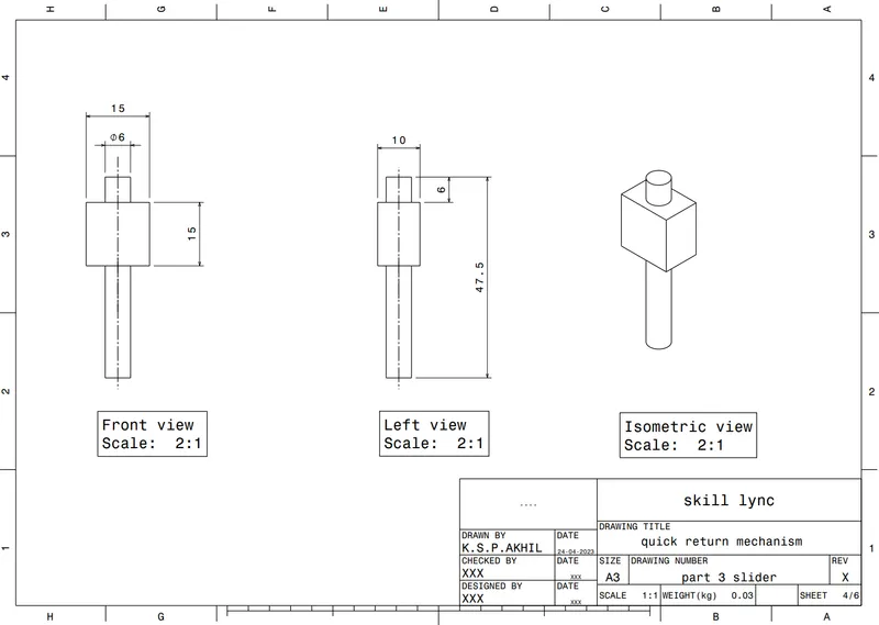
SKETCH AND PAD OF THE SLIDER PART 3
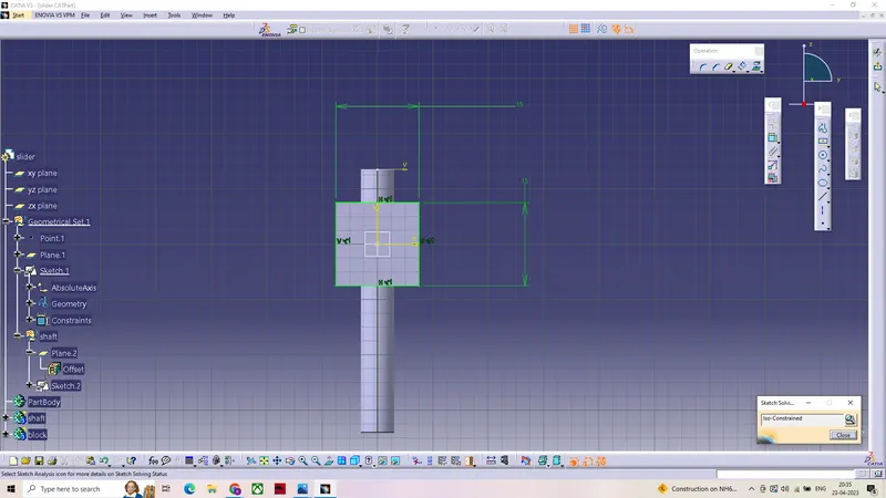
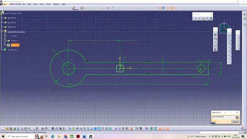
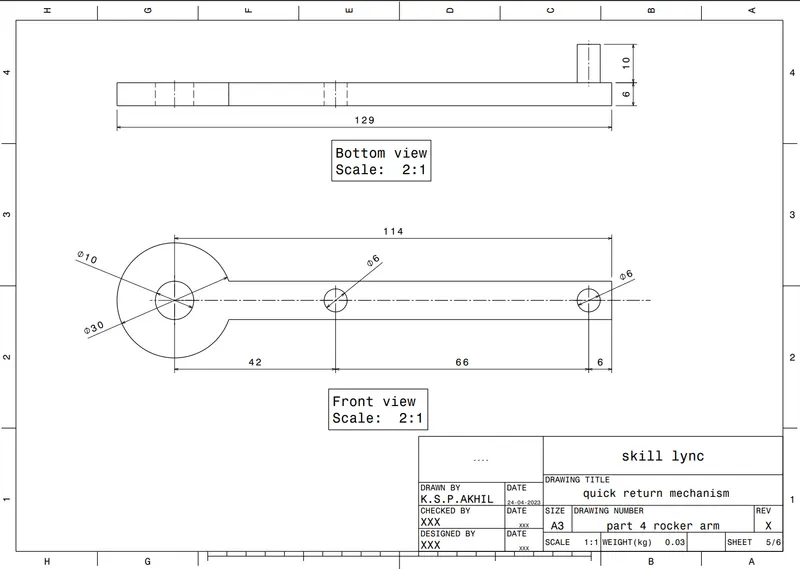
SKETCH OF ROCKER ARM PART 4
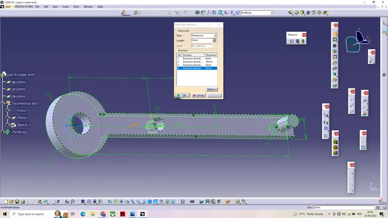
PAD OBTAINED FROM THE SKETCH
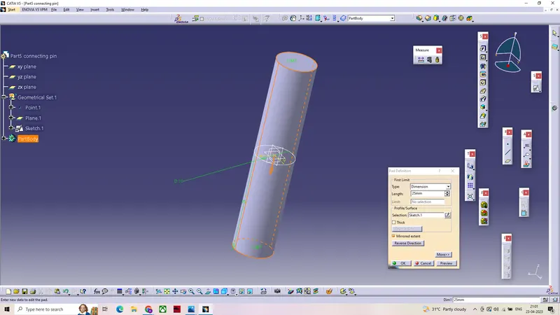
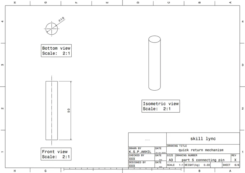
CONNECTING PIN
CREATING A REFRENCE POINT AND PUBLISHING THE REFRENCES IN ASSEMBLY WORKBENCH
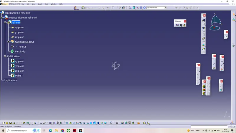
PARTS are insterted into the assembly workbench then Assembling done By using constrains (contact, surface, offset) on reference (axis,points or planes)of the parts .
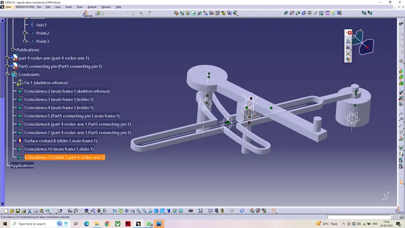
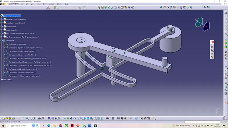
FINAL PRODUCT FROM THE ASSEMBLY
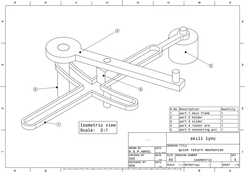
Quick Return Mechanism- 2D drawing Creation
Aim -TO Create 2D drafting form the parts and assembly as given in challenge
2D DRAWINGS FROM THE ASSEMBLED PRODUCT AND ITS PARTS.
CV JOINT - Part creation and Assembly
AIM- Creation of parts with proper dimension and required Assumptions with Proper assembly constraints.
Procedure
- Creating 2D Sketches in CATIA while following the necessary guidelines.
- Then Creating the Solid CATparts from 2D sketches using pad and Boolean operations.
- The created parts are inserted or copied into assembly workbench.
- So that assembly can be done, By using constrains (contact, surface, offset) on reference (axis,points or planes)of the parts .
- Creating draft from the obtained assembly and its parts as specifies.
The given model consists of 3 parts.
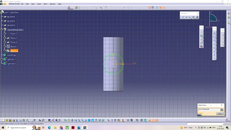
SKETCH OF THE CLINDERS PART 1
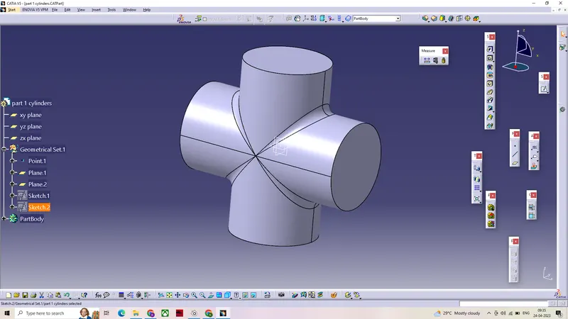
PART OBTAINED FROM PAD AND FILLET
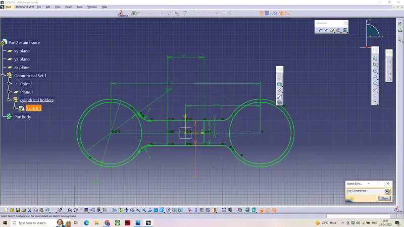
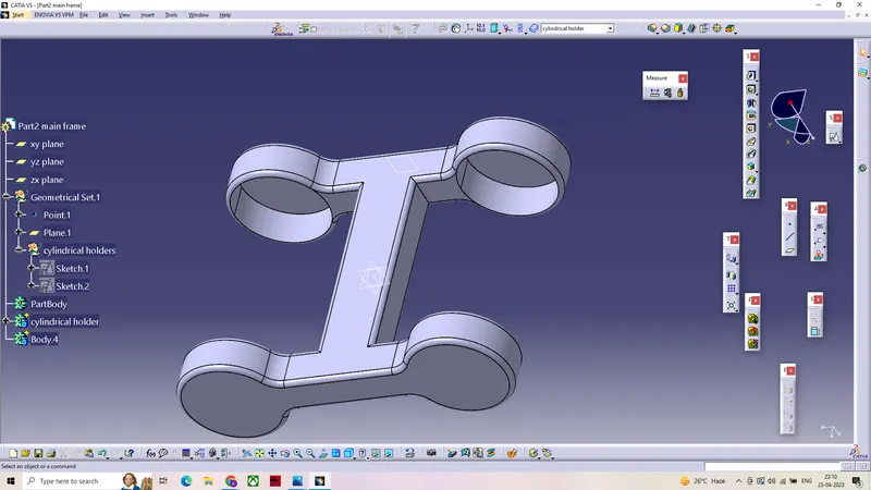
SKETCH OF MAIN FRAME PART 2
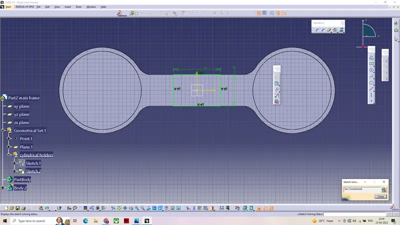
AFTER PERFORMING PAD AND MIRROR ON THE SKETCH
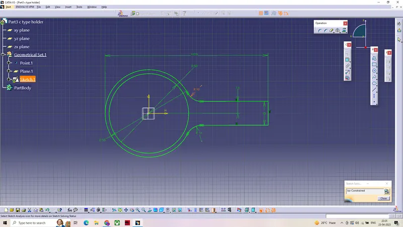
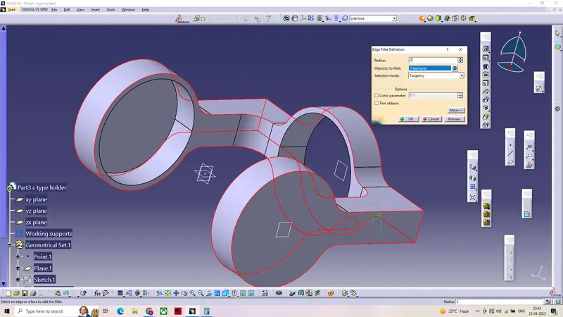
SKETCH OF C TYPE HOLDER PART 3
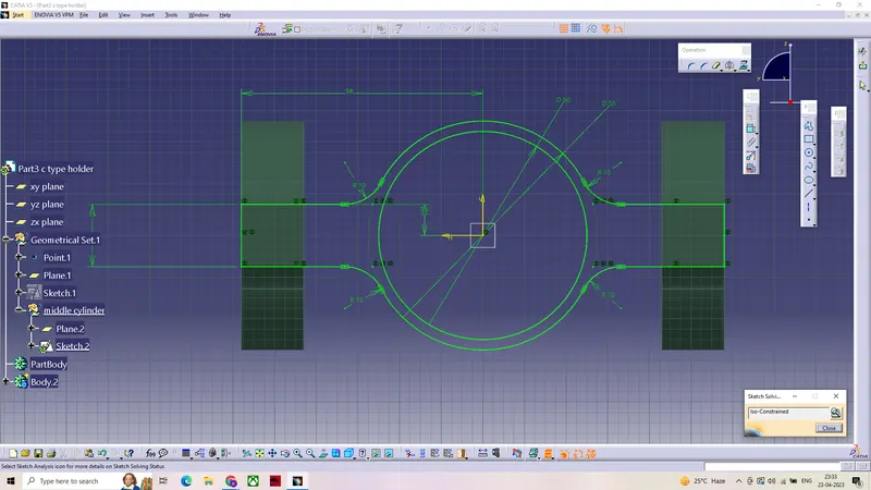
PAD OBTAINED FROM THE SKETCH
PARTS are insterted into the assembly workbench then Assembling done By using constrains (contact, surface, offset) on reference (axis,points or planes)of the parts .
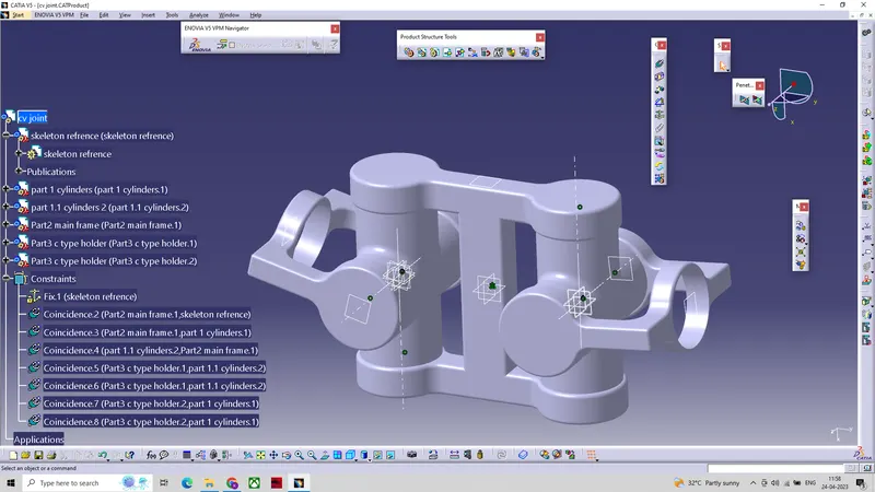
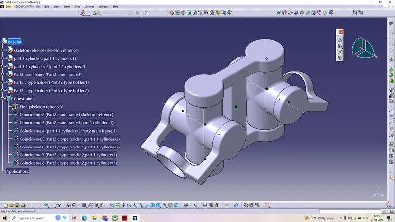
FINAL PRODUCT FROM THE ASSEMBLY
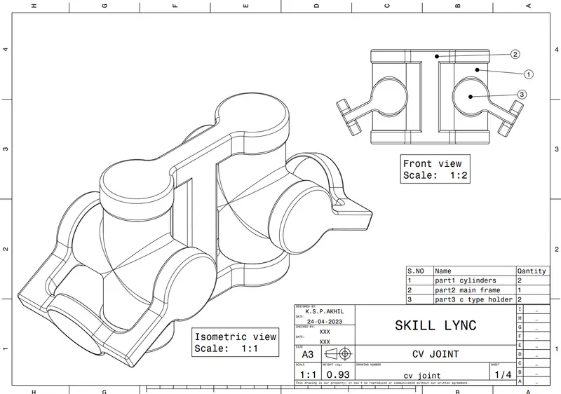
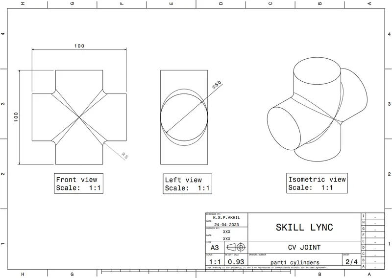
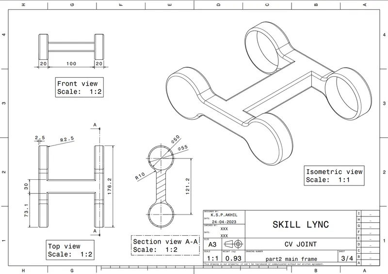
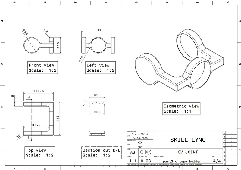
CV JOINT - 2D drawing Creation
Aim -TO Create 2D drafting form the parts and assembly as given in challenge
2D DRAWINGS FROM THE ASSEMBLED PRODUCT AND ITS PARTS.