Week 12- Final project
-:FINAL PROJECT:-
AIM:
- To create a door interior part from the inputs of class A surface along with master section by following the design rules followed in tier 1 and OEM industries in catia v5.
SOFTWARE USED:
CATIA V5
OBJECTIVES:
- Create a sketch by using Positioned sketch
- All the should be sketches should be Iso-Constrained
- Ensured Proper Tree Structure
- Geometrical sets should having a proper name based on the sketches present inside of it
- Create thickened part using master section for reference
- Create the mounting features as per design guidelines in the industry and with master sections
- Creating of Draft analysis & Tooling analysis
- Creation of parting lines and check tooling feasibility
INPUT OF CLASS A SURFACE:
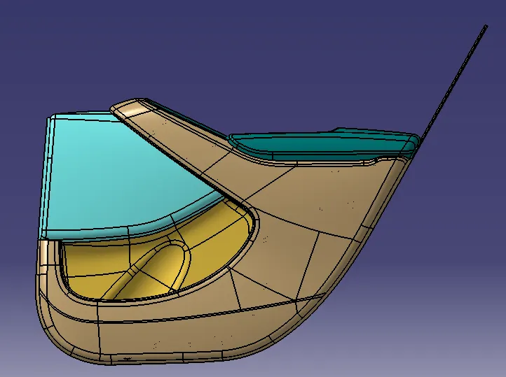
Since the input class A surface is containing four different parts(class A). So class b and c for all the surface has been created in separate catpart. Also performing draft analysis and tooling axis separately. finally all the surface have assembled together in one catproduct
Creating a tooling axis in class A surface:
- The direction in which the mould open and closes is the tooling axis.
- Check the connectivity of the surface and ensure there will be no gap between the surfaces and then define the tooling axis.
- While creating a tooling axis give the tooling axis on a flat length surface or the surface which have a hole on it.
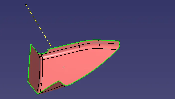
- Create a point on the surface where we are going to create the dummy tooling axis and using line command crate an axis. If there is a circle or flat length surface which is recommended.
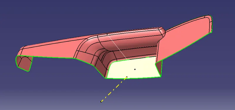
For creating a tooling axis first i extraxt the surface and after creat poin on surface. then i creat one line POINT AND DIRECTION ,
but this method not clear the draft atb 3 degree so after i rotate my compass and see were is minimum area is remaining that is our tooling axis dirtection.
For creat the line in commpass direction lock the compass direction and wwhen we creat a line that time we use compass direction.
Drafting analysis on the Class A surface:
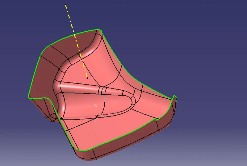
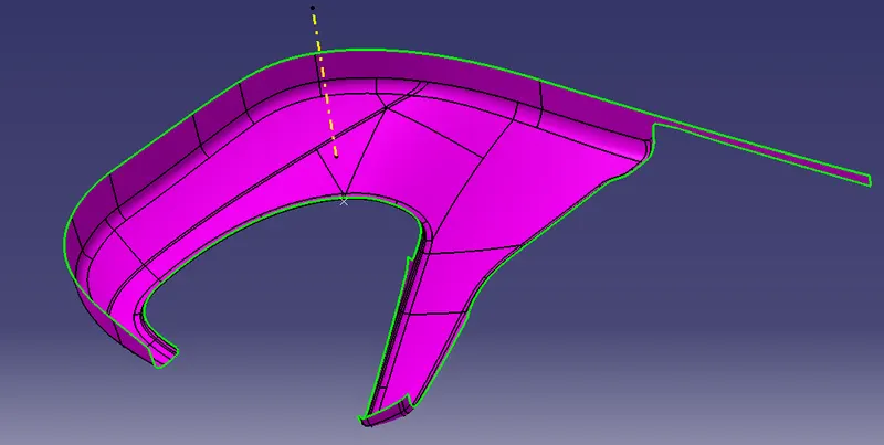
- After creating the solid body we will perform the draft analysis of the whole part body.
- First, change the parameter to material mode and then go to perform draft analysis Go to Insert > analysis > feature draft analysis.
- Click on the compass icon & align with the tooling axis.
- The draft analysis technique is used to analyze whether our part model created in CAD is manufacturable based on the draft condition applied.
- Minimum draft angle is considered as 3 degree.
- step 1= enter part in Catia.
- step 2= Go to Material Mode.
- step 3= go for draft analysis.
- step 4= drag axis bar to the tooling direction of part.
- step 5= check for draft and make parting line as per analysis.
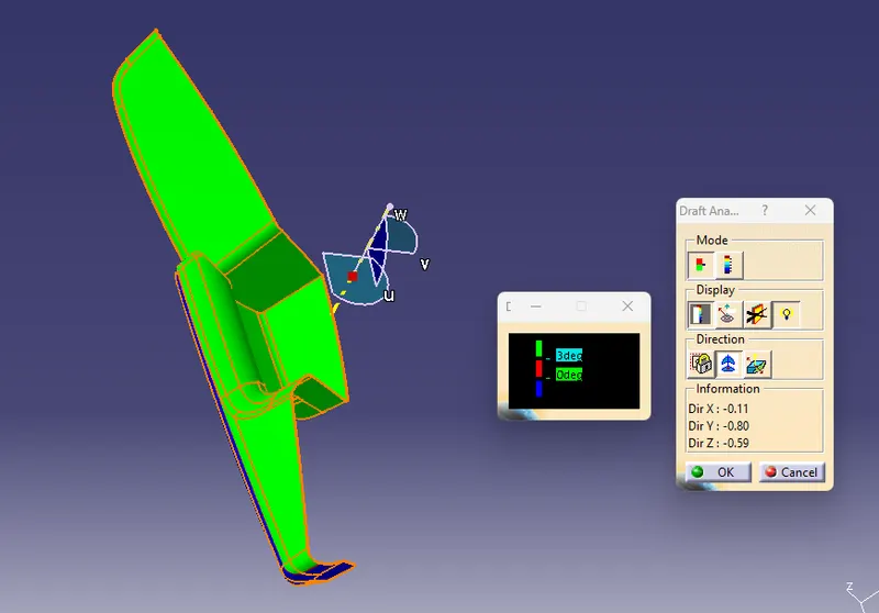
CLASS -A
ARM RESTER
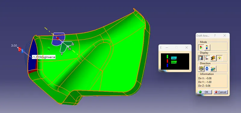
CLASS -A
LOWER MAP POCKET
(SOME AREA IS NOT CLEAR WHIC IS CLASS A FAULT SO REQURED UPDTATION OF CLASS A SURFACE)
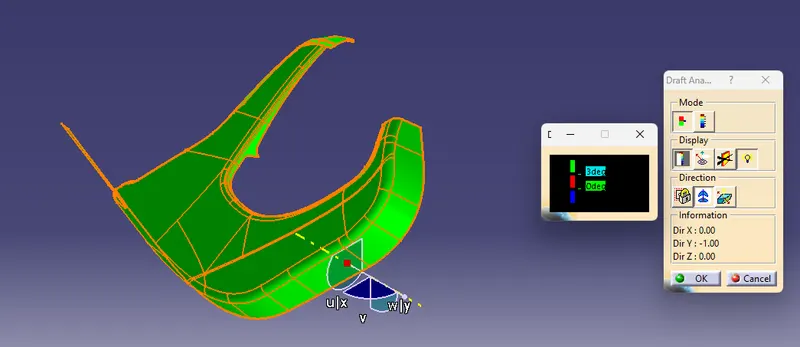
CLASS -A
LOWER SUBSTRATE
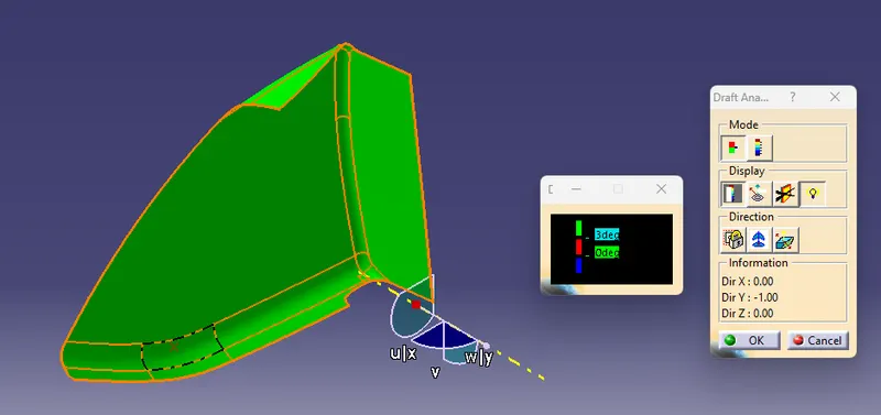
CLASS -A
UPPER MAP POCKET
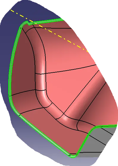
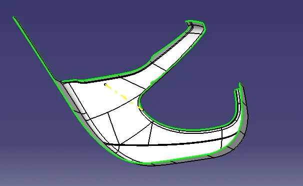
Create A class B surface:
- Class B surfaces are the secondary surfaces in plastic component design.
- In this model Class B-Surface is extracted from the A-surface and it is offseted at 2.5mm in downward direction.
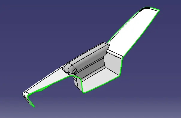
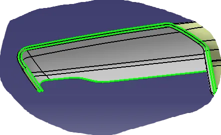
01 ARM RESTER
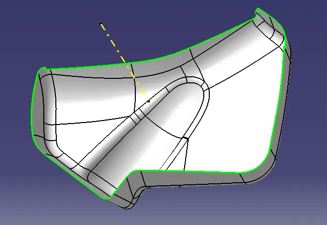
02 LOWER MAP POCKET
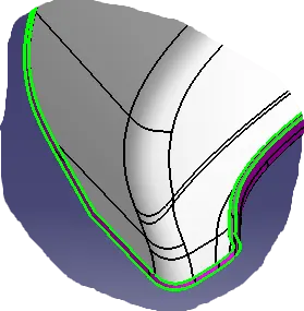
03 LOWE SUBSTRATE
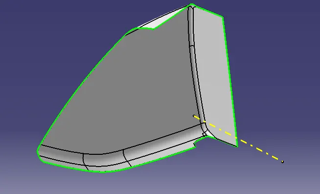
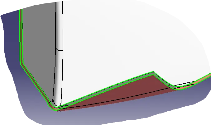
04 UPPER MAP POCKET
Create a class C surface.
- Class C is often specified for interior surfaces not readily visible, surfaces that will be covered by another part when assembled,
- or surfaces which the Customer feels do not need to meet a high cosmetic finish.
- C-Surface connects the class A-Surface and B-Surface. It is created using Sweep command.
- Boundry of the class A-Surface is swept along the tooling direction.
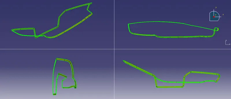
01 ARM RESTER
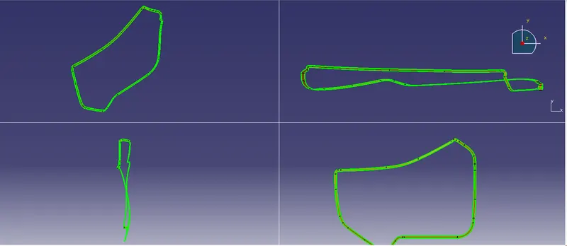
02 LOWER MAP POCKET
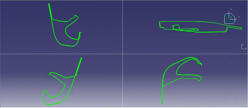
03 LOWE SUBSTRATE
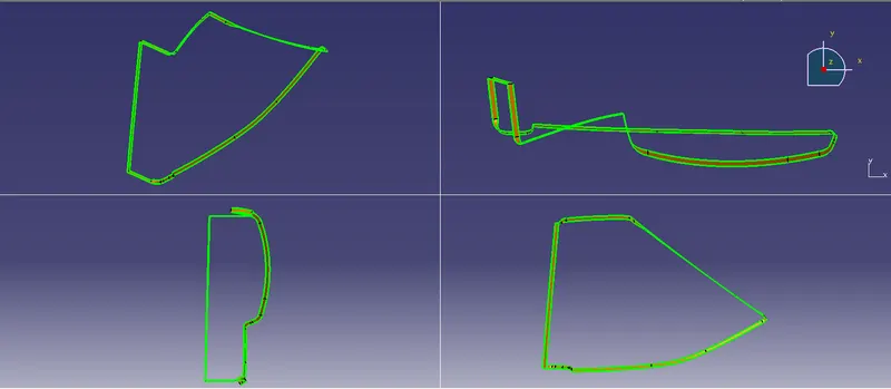
04 UPPER MAP POCKET
CREATION OF B SIDE ATTACHMENT FEATURES:
DOG HOUSE:
- Dog house is an engineering feature used in plastic trim design. Dog houses are used as supporting feature. Sometimes other engineering features like snaps; locators etc. are mounded on them to increase their strength.
- Dog houses are subjected to draft analysis to prevent breakage of the component during ejection from mould cavity. Dog house and other engineering components are built on B-surface.
- Tooling must be cleared for easy ejection of the component, from the core cavity. In order to clear tooling certain value of draft is given to the component. Minimum of 2-3deg is provides on all plastic components.
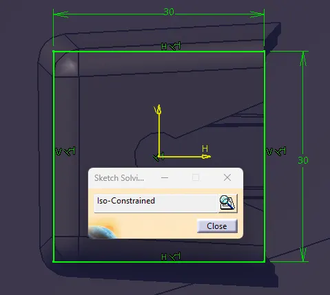
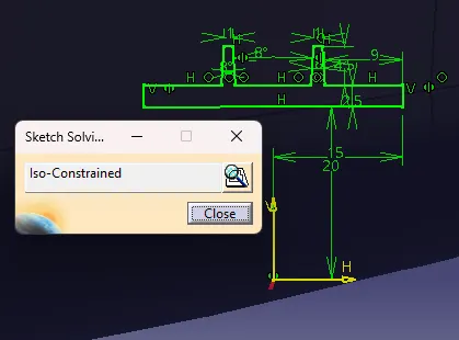
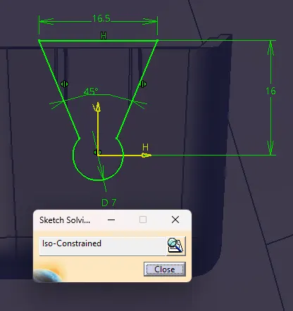
ALL SKETCHES MUST BE ISO -CONSTRAINED
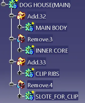
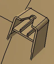

NOTE :- FOR A DOG HOUSE WE REQUIRED SIDE CORE AXIS SO IN ABOVE PICTURE BLUE ARE IS CLEAR WITH THAT AXIS
LOCATORS
- Extract the surface that we going to create locator
- Use positiioned sketch and draw a locator sketch
- Use pad commands for the sketch to till we required
- Draft the locator for minimum of 0.5 degree
- Add fillet 0.5mm o all faces
- Assemble the locator to lower subtrate solid
- Maintain a 50mm minimum between two locator
- Translate the locator to wherever we need
- Trim the all heat stakes with lowersubstrate solid
- Maintian a height more than heat stake
There are two tpes of loctors which is majorly used for guide the component or to take proper position in assembly
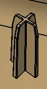
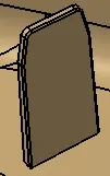
4 WAY LOCATOR 2 -WAY LOCTOR
We can see in above picture in loctor top side entry chamfer is given so assmble component esaly insert in locator
CHAMFER SIZE- 10DEGREE X 10mm(ANGLE X DISTANCE)
HEAT STAKES
Heatstakes is known as thermoplastic staking is the process of joining two dissimilar metals together
- Extract the surface that we going to create heat stake
- Use positiioned sketch and draw a heat stakes sketch
- Use pad commands for the sketch to till we required
- Draft the stakes minimum of 0.5 degree
- Add fillet 0.5mm o all faces
- Assemble the heat stake to lower subtrate solid
- Maintain a 50mm minimum between two heat stakes
- Translate the heatstakes to wherever we need
- Trim the all heat stakes with lowersubstrate solid
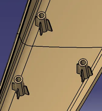
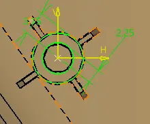
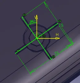
For supporting the heat stake we creat a ribs which is also drafted with minimum 0.5 degree , And also our flnage is rested on ribs so ribs height is deside acroding to flnge height.
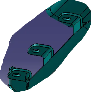
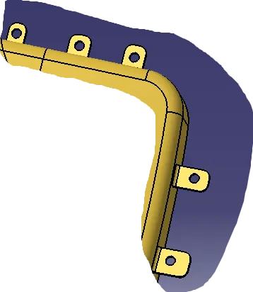
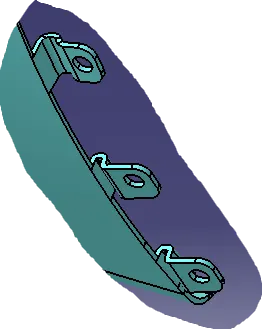
FLANGE
Create a flange for attachment of heatstakes and locators at lower substrate.
For creating a flange we can use commond likes
- SWEEP
- EXTRUDE
- TRIM
- THICNESS(for convert into solid)
DRAFT ANALYSIS REPORT:
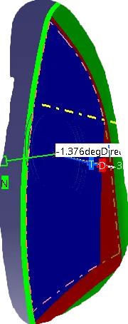
FOR A FINAL PARTS
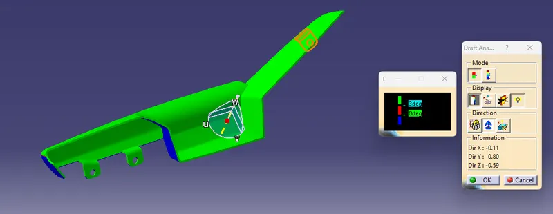
01 ARM RESTER
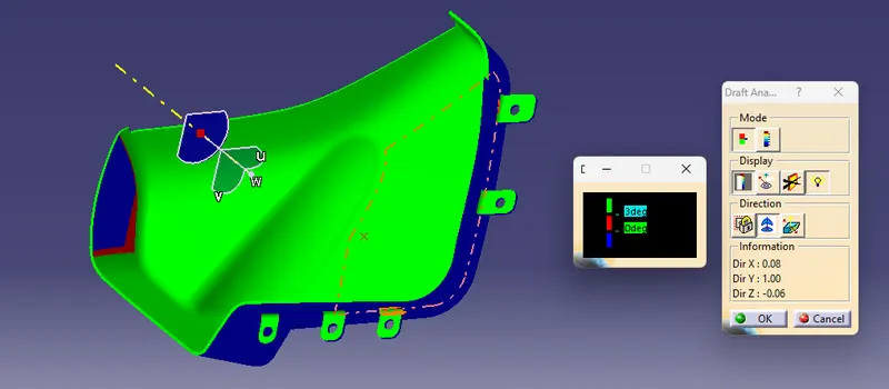
02 LOWER MAP POCKET(BOTTOL HOLDER)
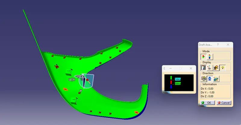
FOR SOME B SIDE FEATURE WE REQURED 0.5 DEGREE DRFAT SO IN ABOVE PICTURE SOME B SIDE FEATURE
(LIKE DOG HOUSE HEAT STAKE LOCTORS ...) IS NOT CLEAR WITH 3 DEGREE DRFAT SO IN SECOND PICTURE SHOWN DRFAT ANALYSIS WITH 0.5 DEGREE
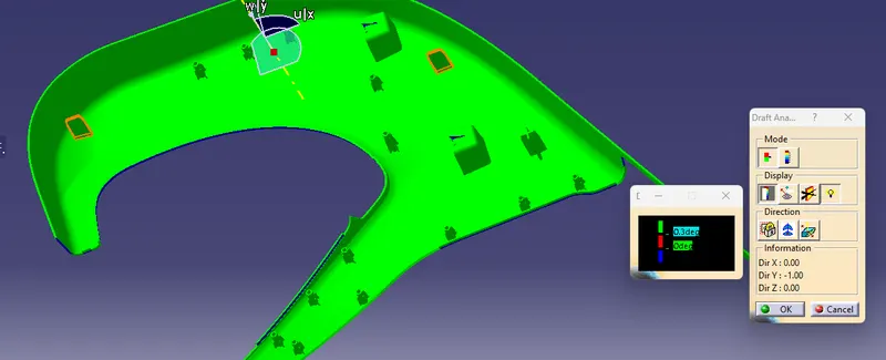
03 LOWER SUBSTRATE
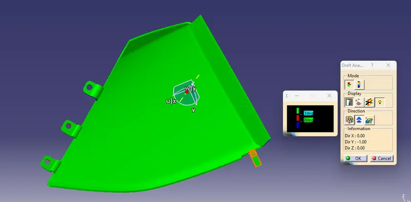
04 UPPER MAP POCKET
MODELS IN VARIOUS ORINTATION SOLID:
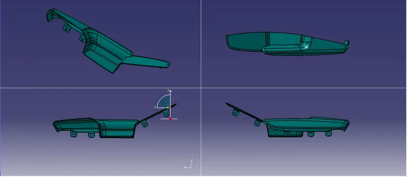
01 ARM RESTER:-
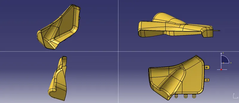
02 LOWER MAP POCKET(BOTTOL HOLDER)
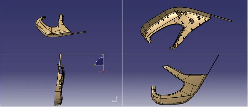
03 LOWER SUBSTRATE
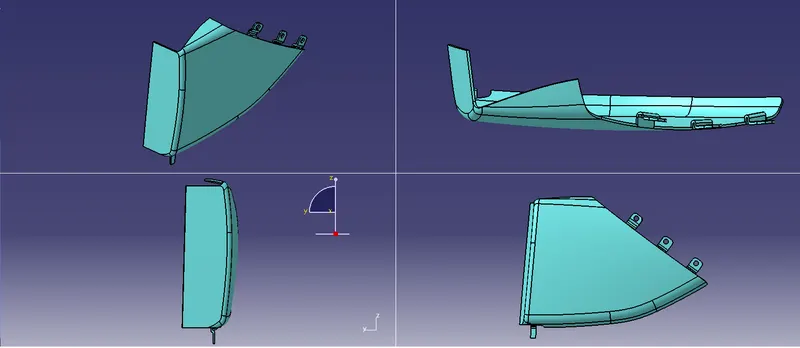
04 UPPER MAP POCKET
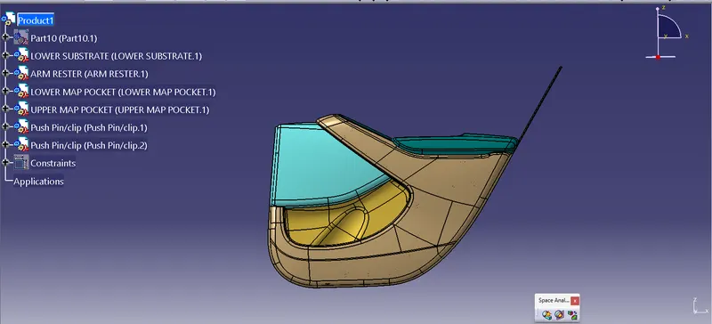
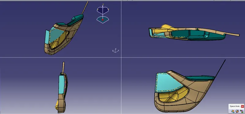
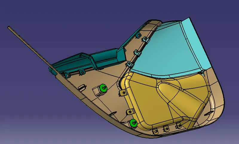
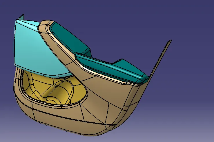
DOOR TRIM PANEL:-
PREPARED BY:-
SHYAM PATEL