Week 10 - Challenge 2- Attachment Feature Creation (Dog House)
Screenshots of the class A surface draft analysis :
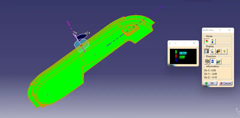
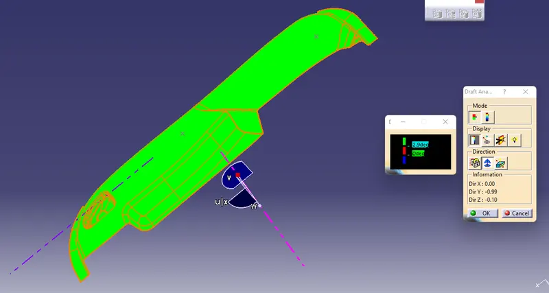
Screenshots of the completed design draft analysis :
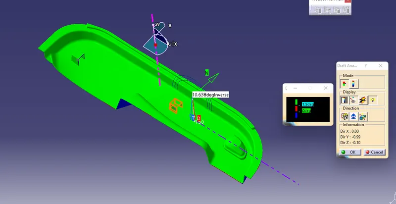
CLEAR DOG HOUSE IN TOOLING AXIS AT 1.5 DEGREE DRAFT
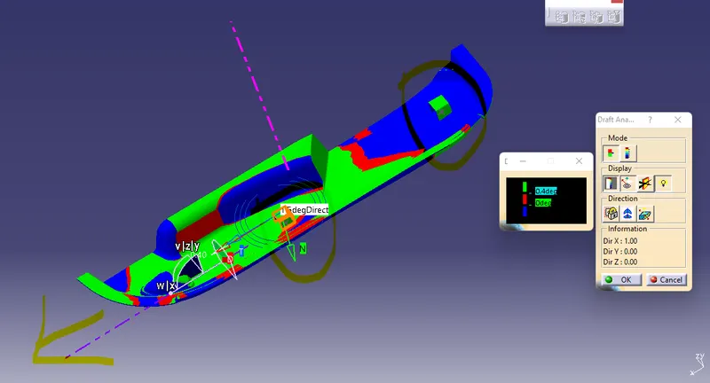
ALSO CLEAR IN LIFTER DIRECTION
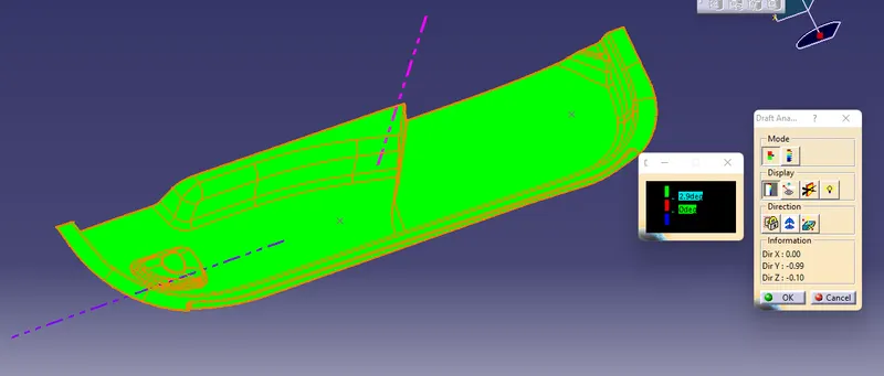
BODY CLEAR IN TOOLING DIRECTION AT 3 DRGREE DRAFT
Screenshots of the completed design in various orientations:
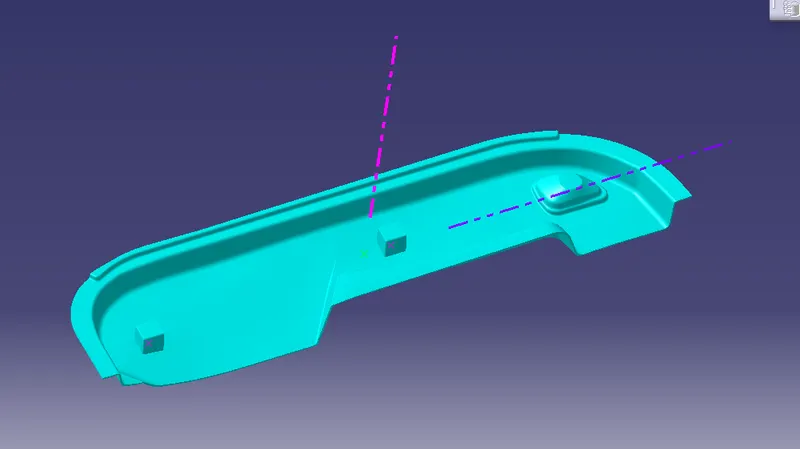
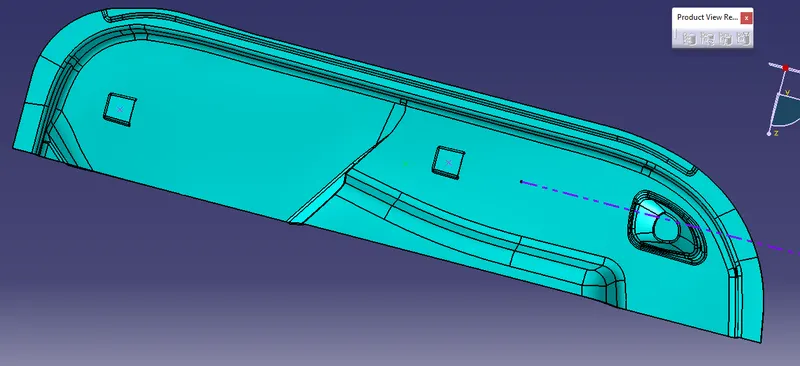
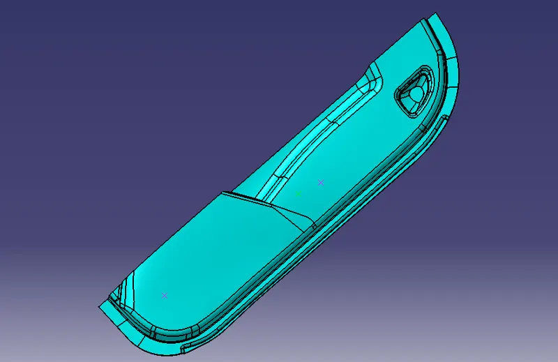
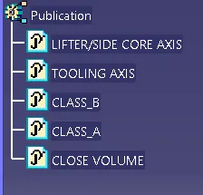
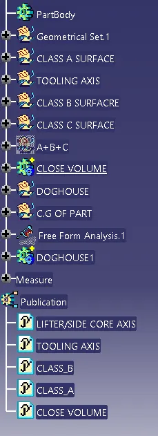
STRUCTURE TREE AND PUBLICTION:
Report:
As we've discussed in previous examples that draft analysis is performed on the component for checking wethere the draft we created is easily manufacturable or not.
Tooling axis is the main axis along with which the product will be drafted and the main direction of motion will be in that particular direction.
Tooling Axis:
In here, I've searched for the methods online. I found this new method which was highly used by the industrialists. The name of the method is Moment of inertia method. In CATIA software there is a feature which allows you to find center of gravity of the product. So according to that we find point. We created a line in most cover area direction (z-direction) accronding to below not
NOTE:- put your part in isometric view and see in which direction our part more clear that is our tooling direction but some time in complexe part we need to more work on it to find the tooling axis so accroding to draft angle we genarate new line accronding to angle recuired(normal/angle to curve) with help of using this line commond and after part is clear then it is our tooling axis