Week 12- Final project
Door Trim
Objective:
Development of a Door Trim panel
Creation of CAD model considering following inputs as like in OEM and tier1 companies
Things to consider during this project:
- To create the individual tooling axis for the part and perform the draft analysis for given class A surface.
- To create the class B and C surface with reference to given class A Surface
Input
Class-A surface and master section for Engineering Features
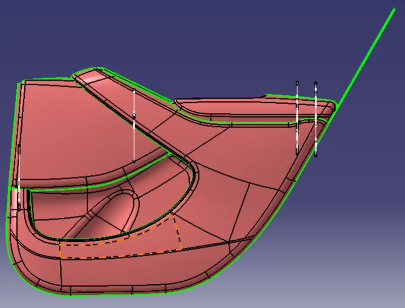
Component included in Door Panel
- Arm Rest
- Lower Substate
- Bottle Holder
- Map Pocket
Design Procedure
1. Arm Rest
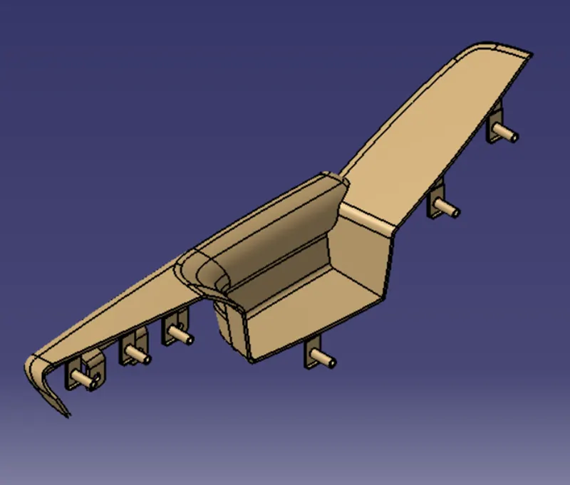
Extracting the Given Class-A Surface in Arm Rest
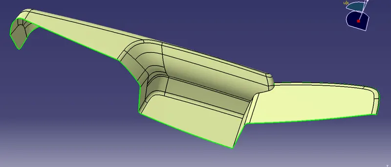
Checking the surface quality of class A surface
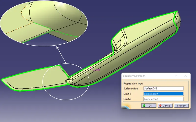
Improvised Class-A Surface
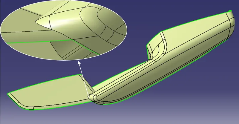
Creating Tooling Axis
Tooling Axis 1
Method Used: Normal to Surface
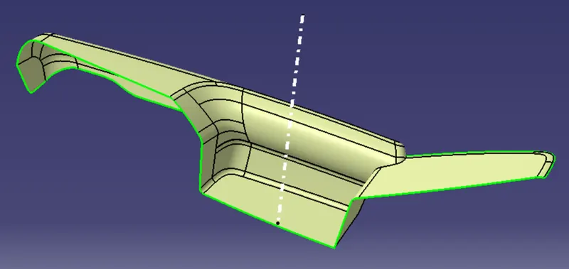
Tooling Axis 2
Method Used: Bisecting Method
Pulling the reference from the master section in order to make a second tooling axis for clearing class A and engineering features.
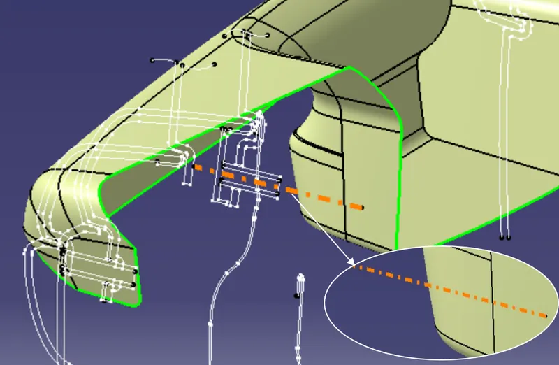
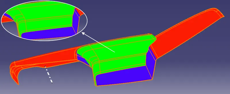
Draft Analysis Result w.r.t. Tooling Axis 1
Red and Blue colour area are visible, which is not getting cleared with Tooling Axis 1
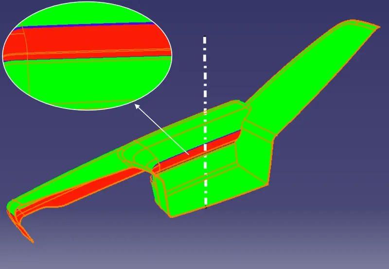
Draft Analysis w.r.t. Tooling Axis 2
The above mentioned unclear area is clear w.r.t. Tooling Axis 2
Creating Class B Surface
Measuring the offset distance between the Class-A & B Surface with Master Section
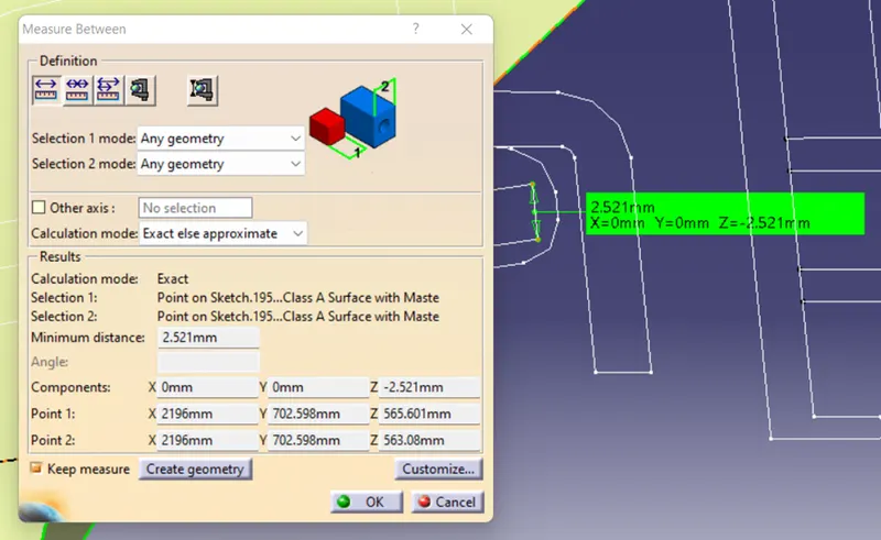
As per the master section we are going to give Class-A surface offset of 2.5mm
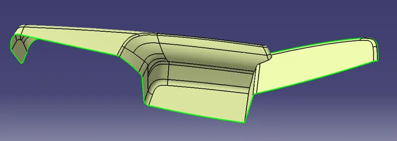
Creating Class-C Surface with reference to Class-A Surface
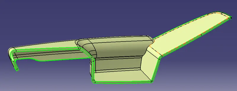
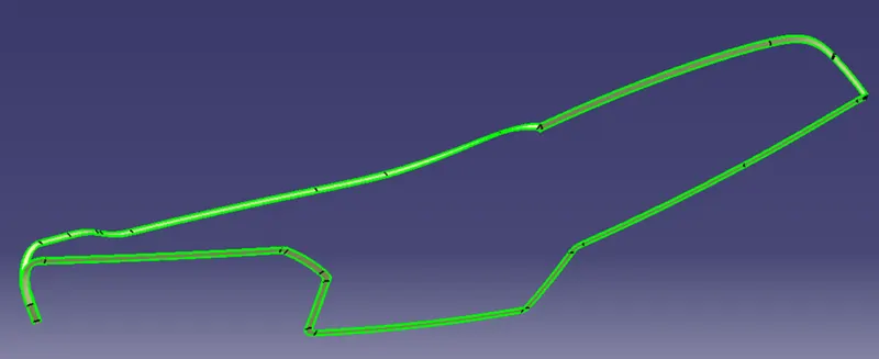
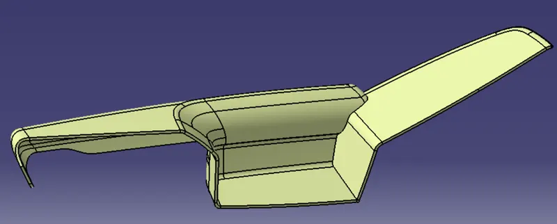
Creating the closed body by joining the Class-A, B and C surface
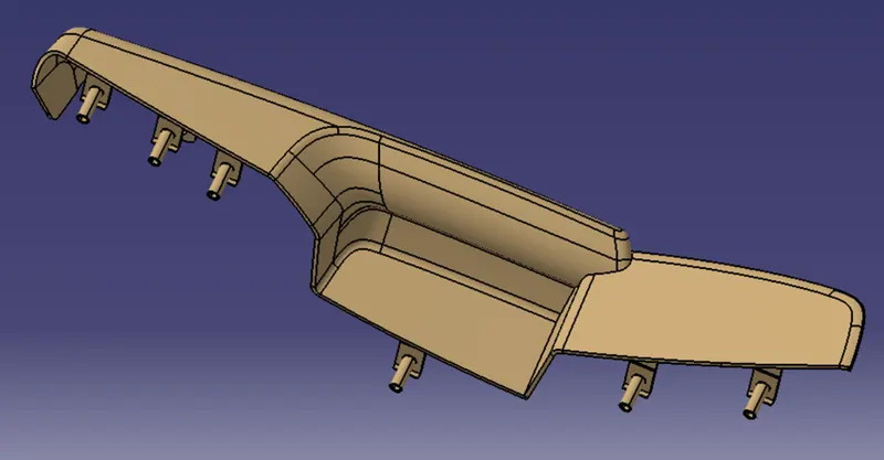
Creating the flanges on Arm Rest
W.R.T. master section we will get to know the dimension of flange and with respect to counterpart position of heat stakes and locating ribs of Lower Substrate position.
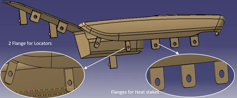
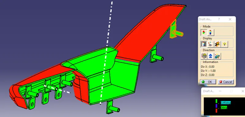
Engineering Features Draft Analysis
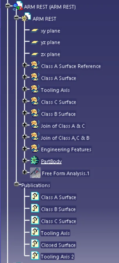
Feature Tree of Arm Rest
2. Lower Substrate
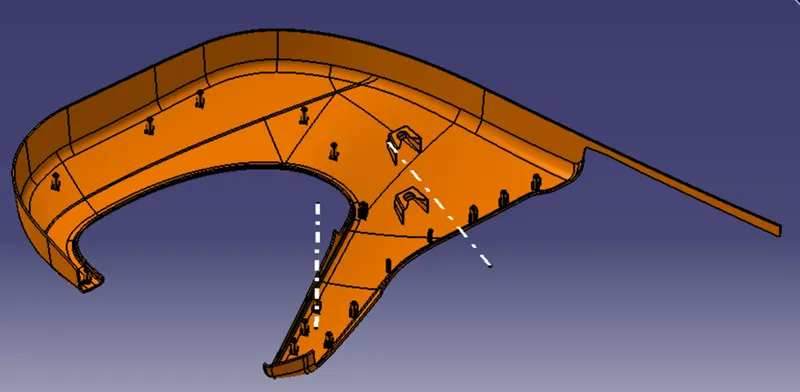
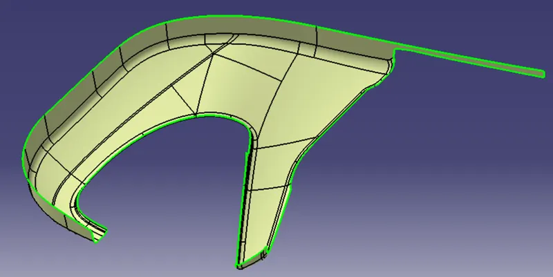
Extracting the Class A Surface from the Input
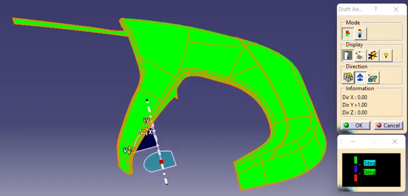
Tooling Axis
Method used: Bisecting method w.r.t. to master section
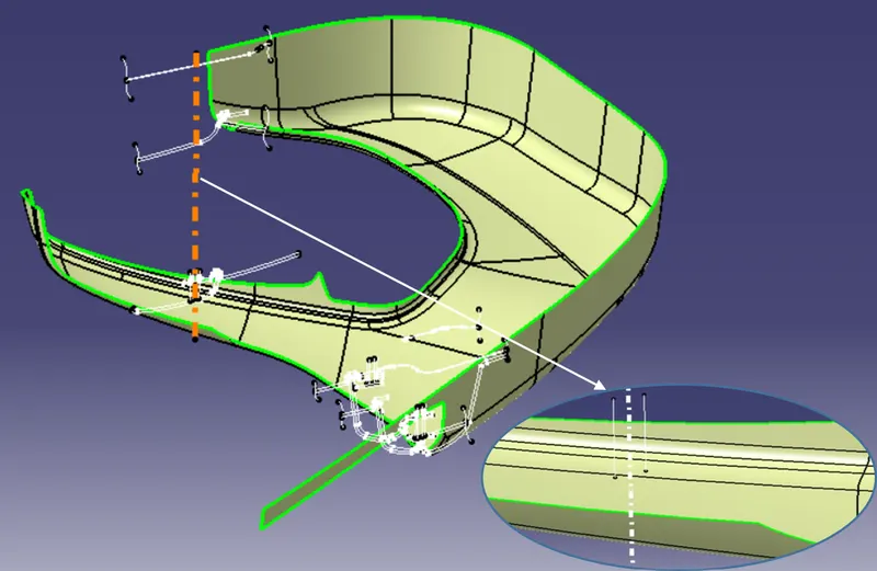
All the surfaces are getting cleared with the current tooling axis.
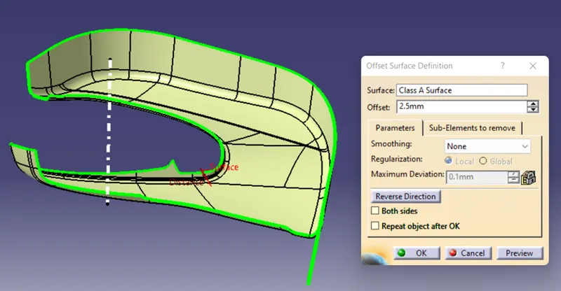
Creating the Class B Surface
Measuring the distance between the class A and B surface
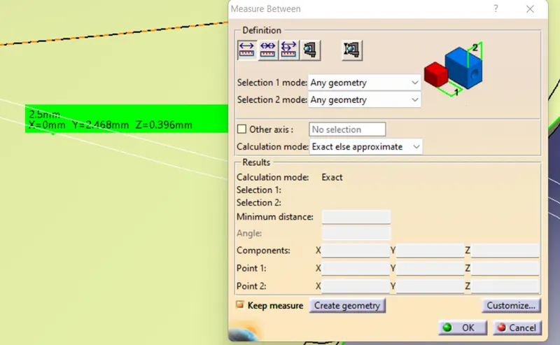
As per the master section the distance between the class-A and B surface is 2.5mm
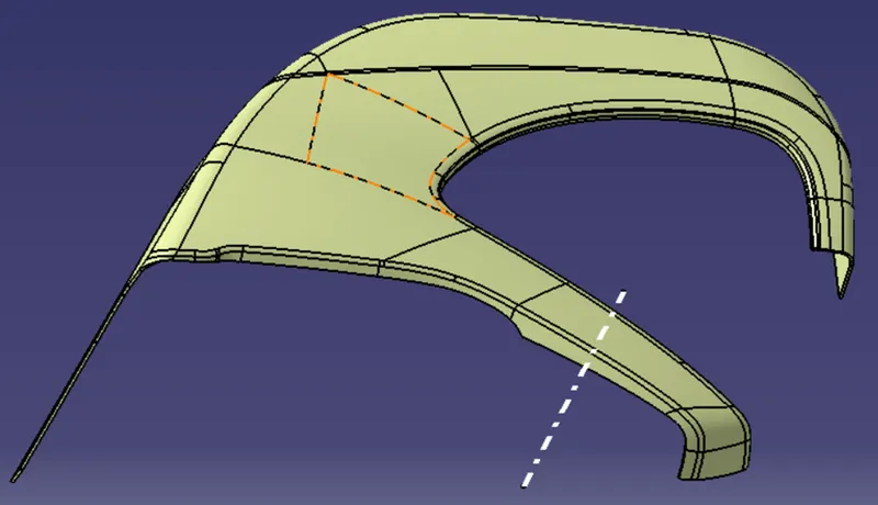
Creating Class-C Surface with reference to Class-A Surface
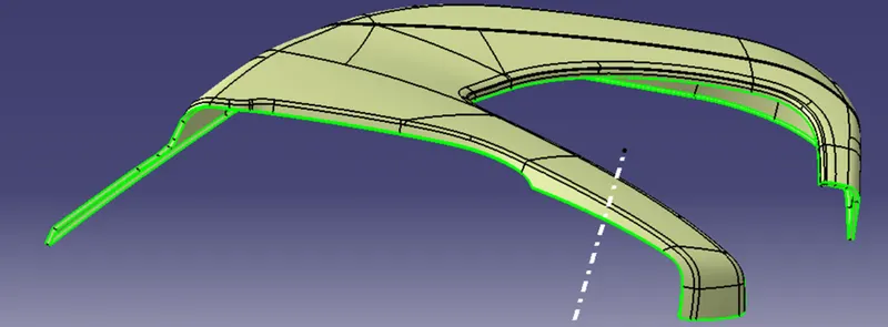
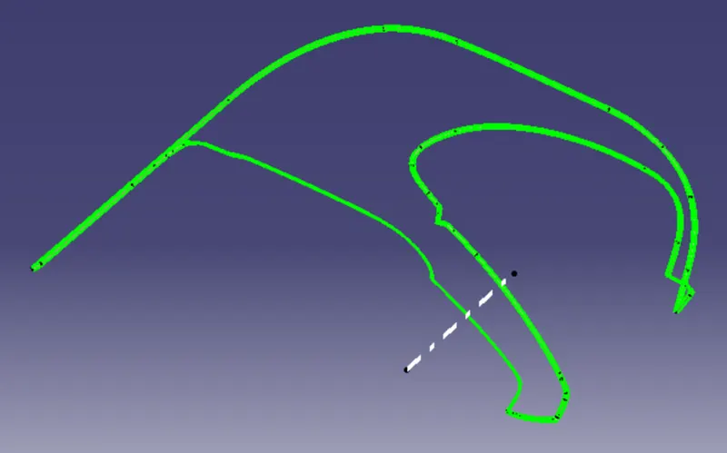
Closed Surface
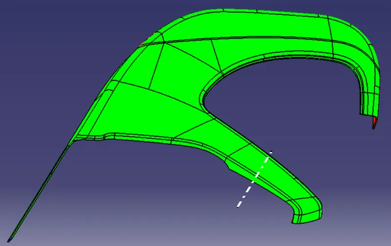
Creating the closed body by joining the Class-A, B and C surface
Closed body draft analysis
Creating of Heat Stakes, Locator Ribs and Dog House
Heat Stakes
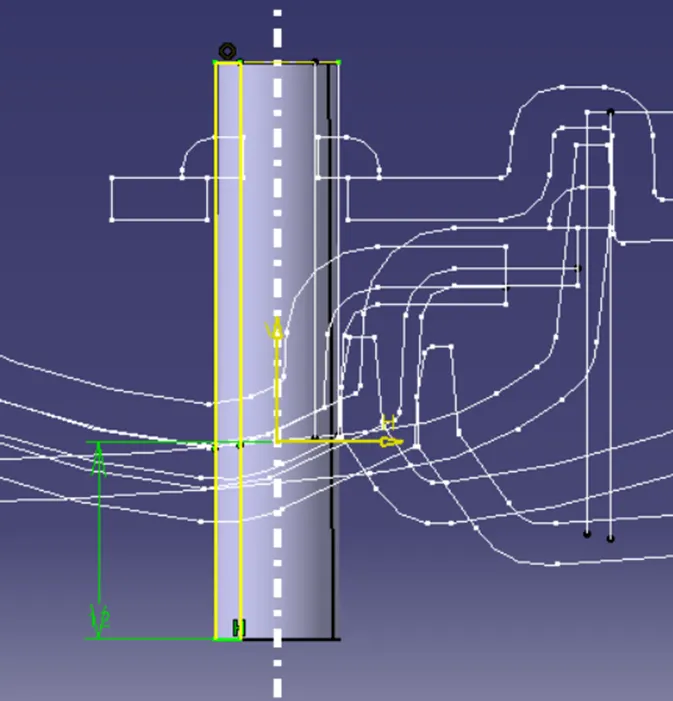
Extracting the inputs from the master section
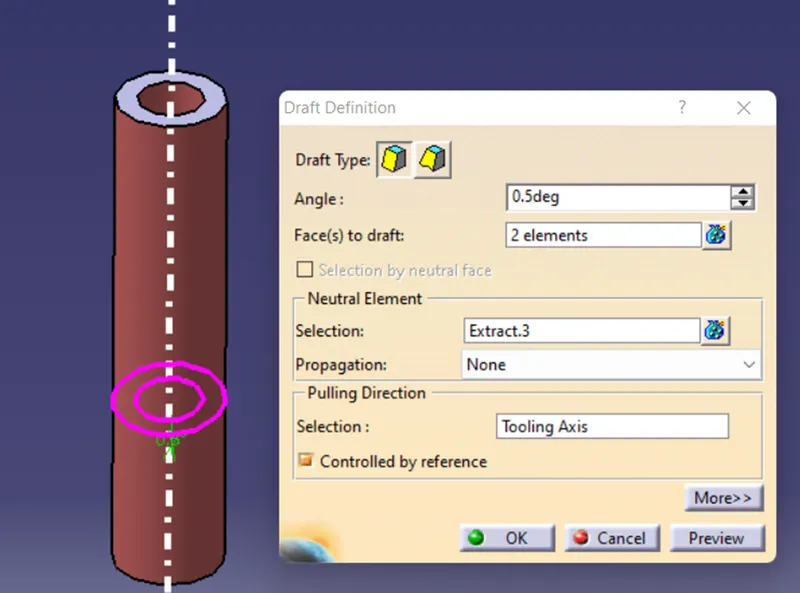
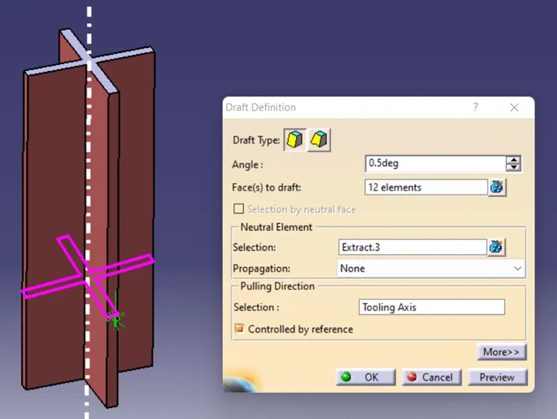
Adding draft on both surfaces of 0.5° w.r.t. tooling axis
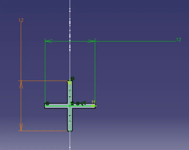
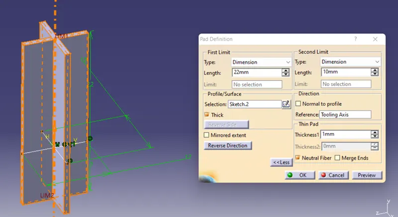
Adding draft analysis of 0.5° w.r.t. tooling axis
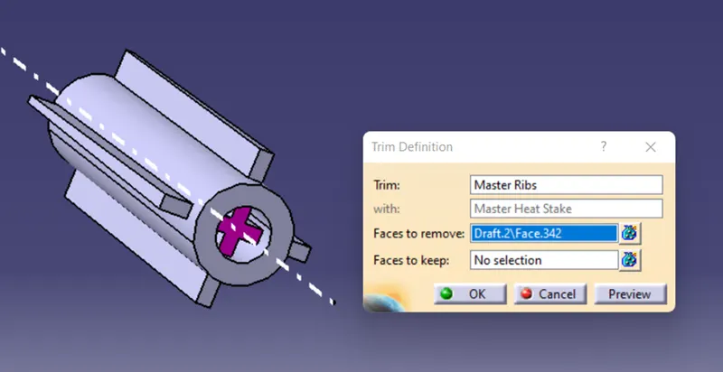
Applying Union trim on both the bodies to make a Heat Stakes
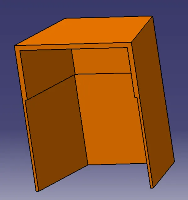
Dog House
Closed body surface
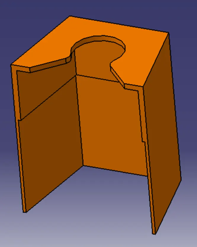
With pocket command we will remove the material for push pin
Applying the fillet and draft on dog house
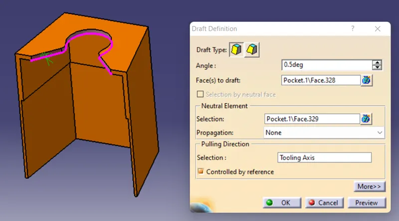
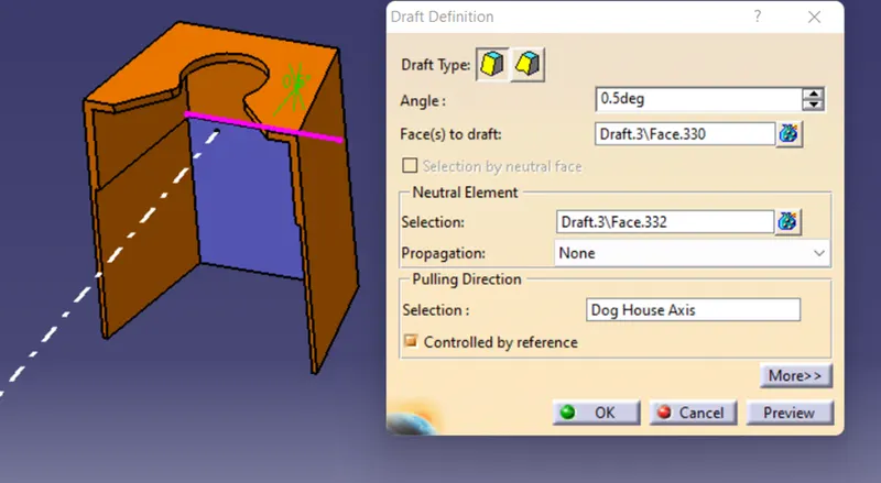
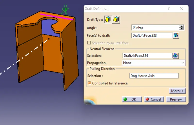
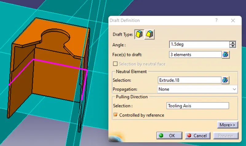
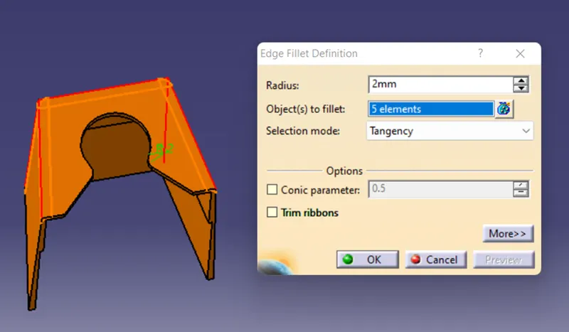
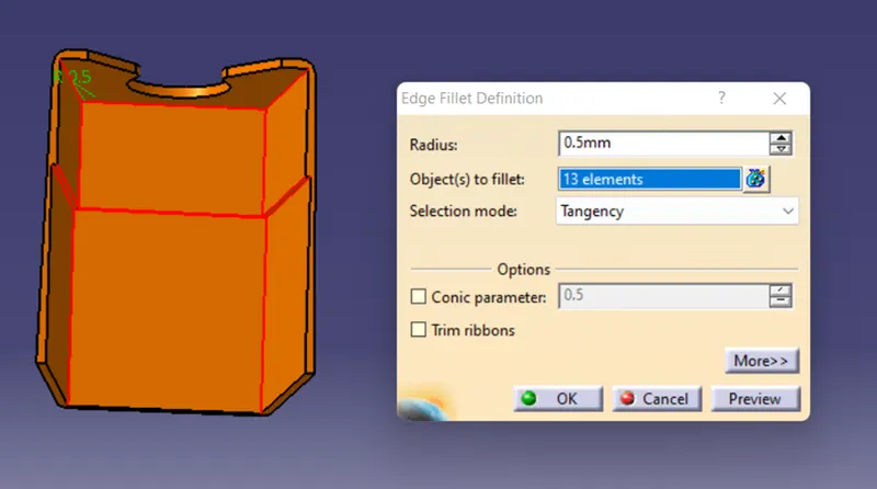
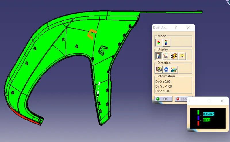
Once after the translation of heat stakes and dog house to all the location, we will perform the draft analysis.
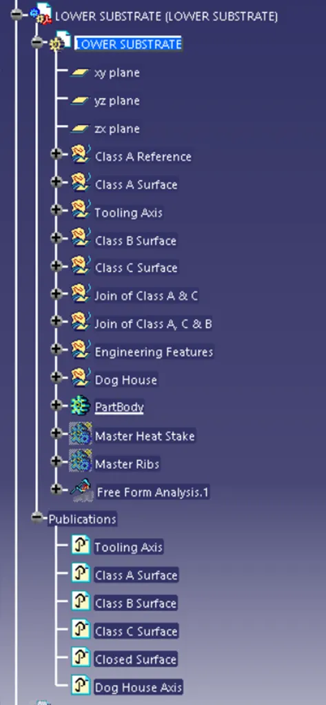
Feature Tree
3. Bottle Holder
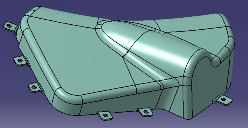
Extracting the class-A surface from the input
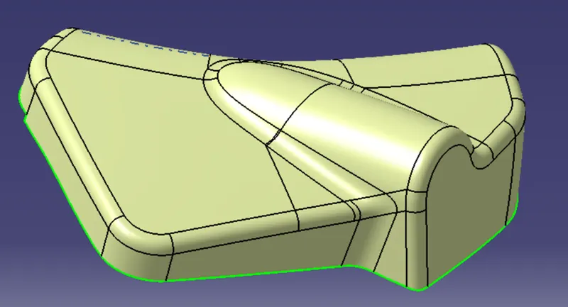
Performing the surface quality check
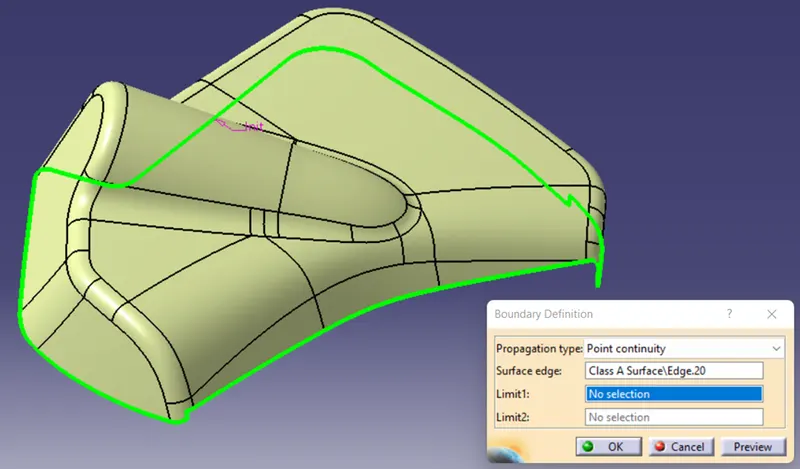
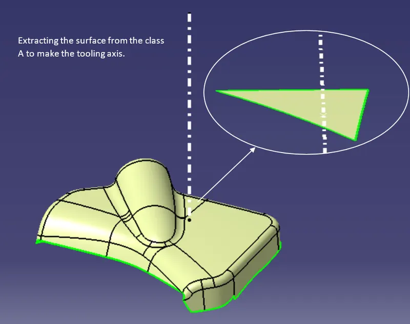
Creating Tooling Axis
Method Used: Normal to surface
Draft Analysis of Class-A Surface
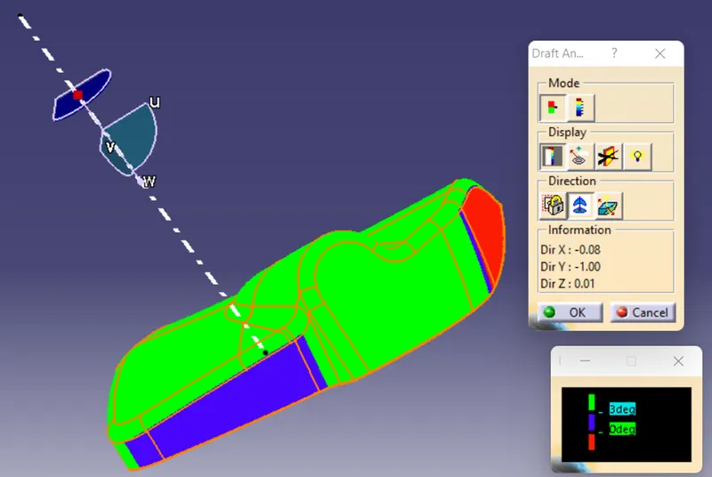
Note: Few surfaces are appearing in blue and red which are not getting clear, hence need to reach out to class-A surface creator team for updated model.
Creating Class-B Surface
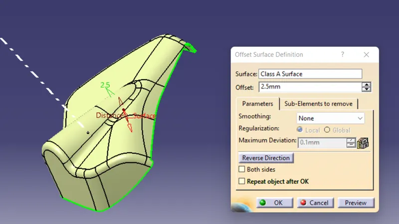
Creating Class-C Surface with reference to Class-A Surface
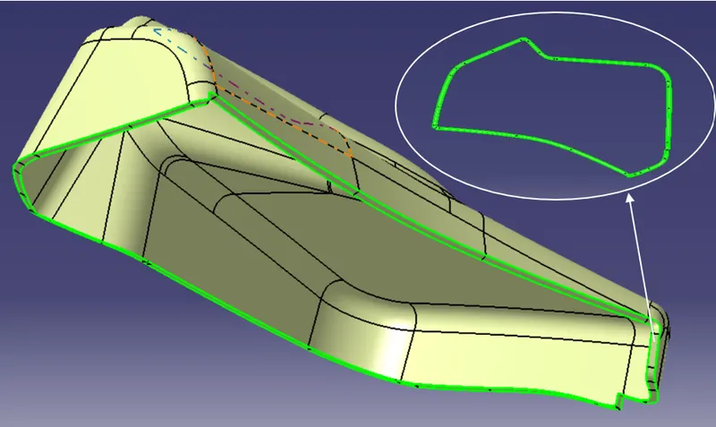
Closed Body
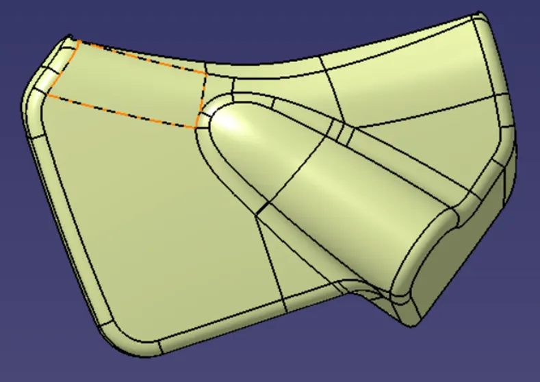
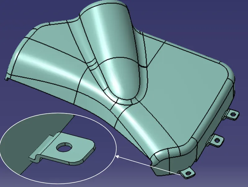
Creating Flanges on closed body
W.R.T. respect to counterpart position of heat stakes of Lower Substrate position, we will add the flange on those location
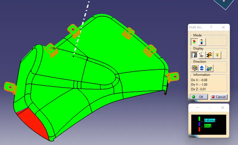
Final Draft analysis for flanges
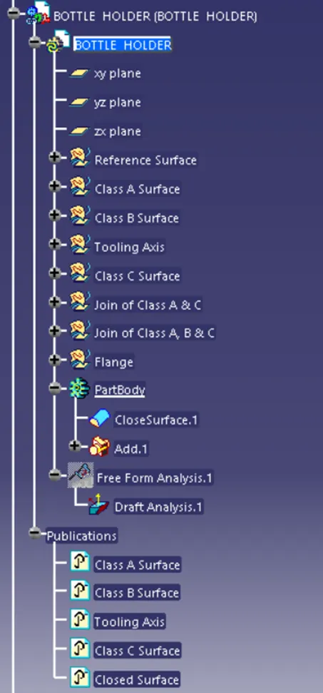
Feature Tree
4. Map Pocket
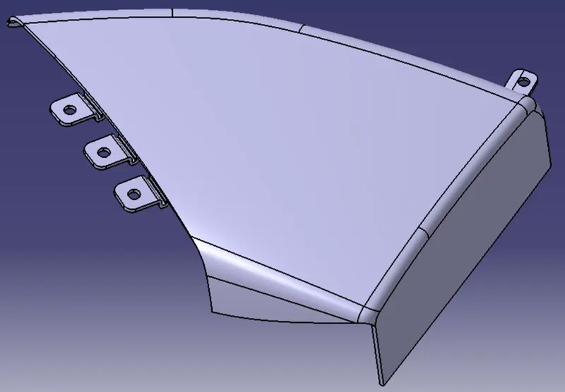
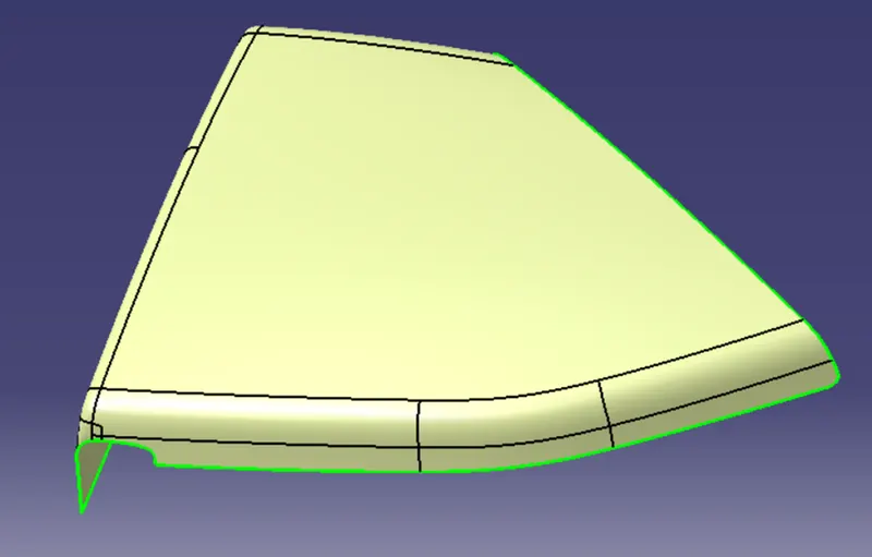
Creating Class A surface
Extracting Class-A surface from input
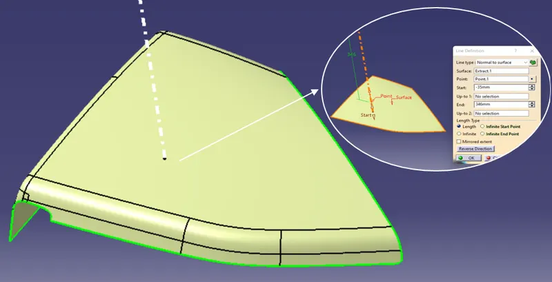
Creating Tooling Axis
Method Used: Normal to Surface method
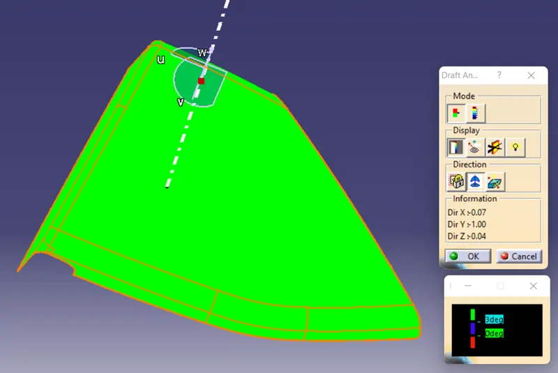
Draft analysis of Class-A surface
Creating Class B Surface
Measuring the offset distance between the Class-A & B Surface with Master Section
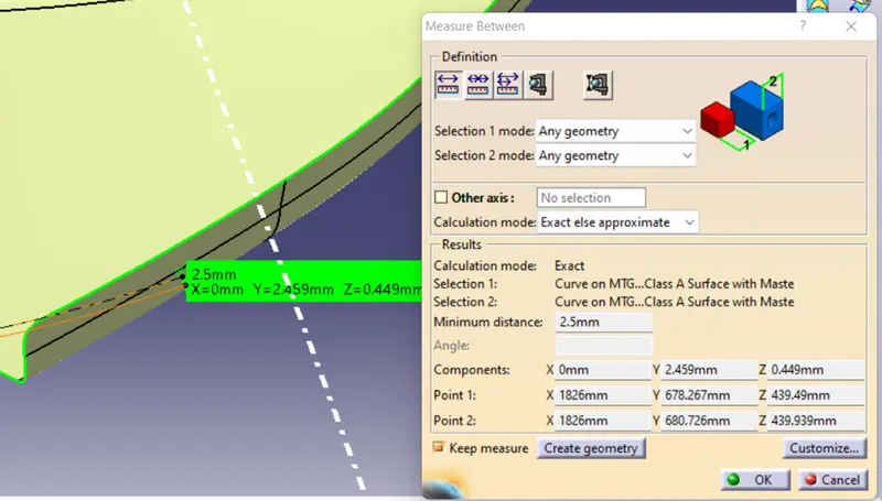
As per the master section, we need to give offset of 2.5mm for Class-B surface
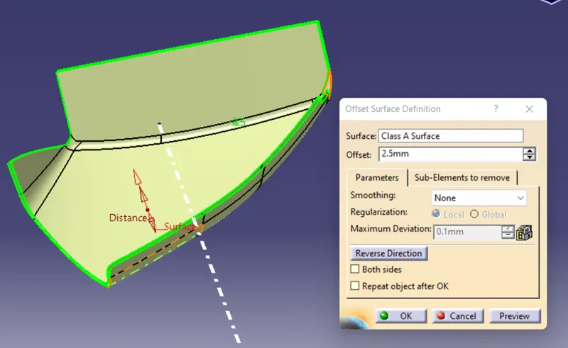
Creating Class C Surface
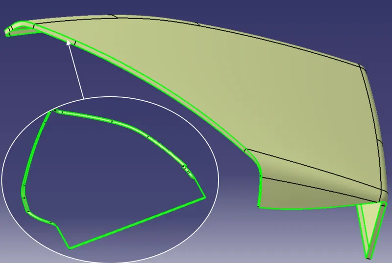
Creating the closed body by joining the Class-A, B and C surface
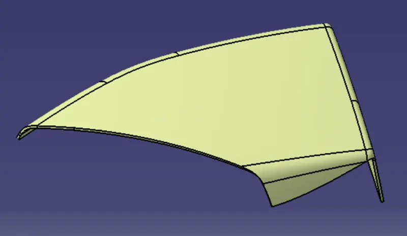
Creating Flange
W.R.T. master section we will get to know the dimension of flange and with respect to counterpart position of heat stakes and locating ribs of Lower Substrate position.
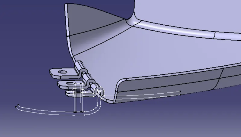
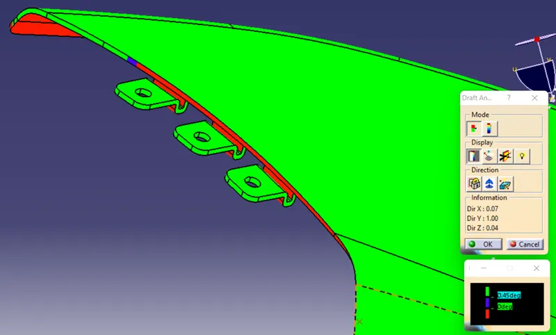
Draft analysis for Flange
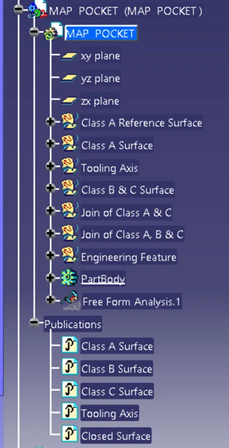
Feature Tree
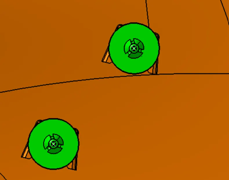
Mounting of Push Pin Clips on Dog House
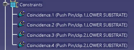
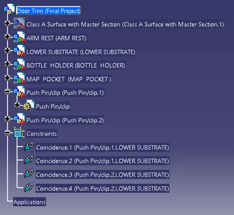
Assembly Constrained
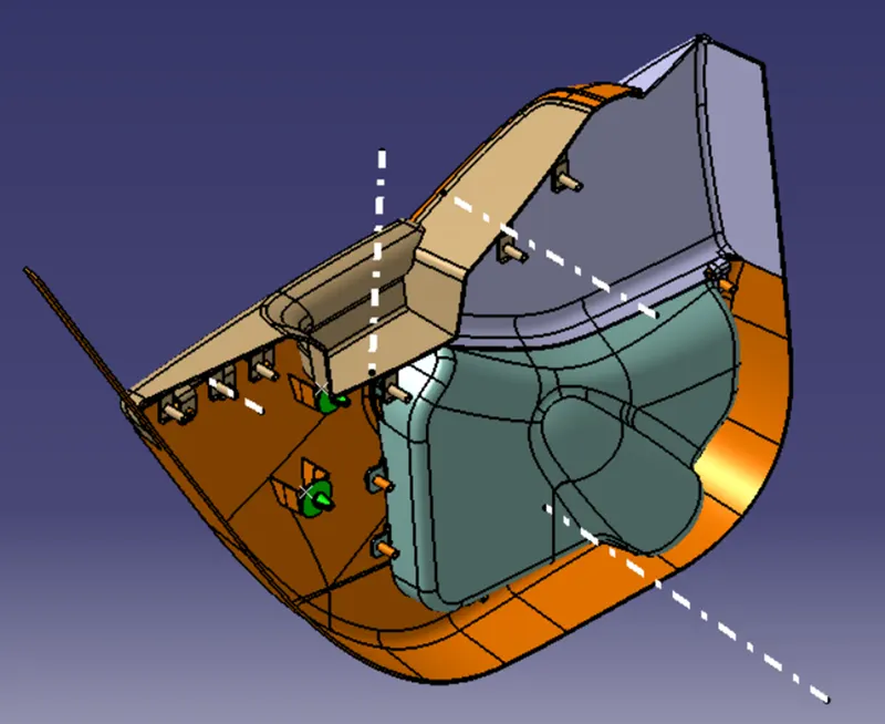
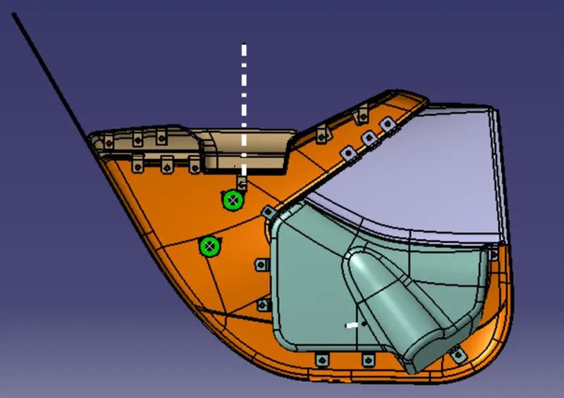
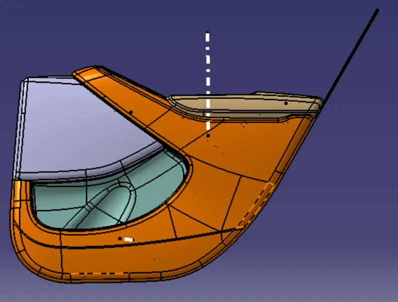
Final Body
Isometric View
Bottom View
Top View
Feature Tree
Conclusion
Door Trim was made with OEM guidelines using Part Workbench and Generative Shape Design Workbench using CATIA V5