Week 12- Final project
AIM: To create a CAD model considering the OEM standards from the Class-A surface of a Door Panel.
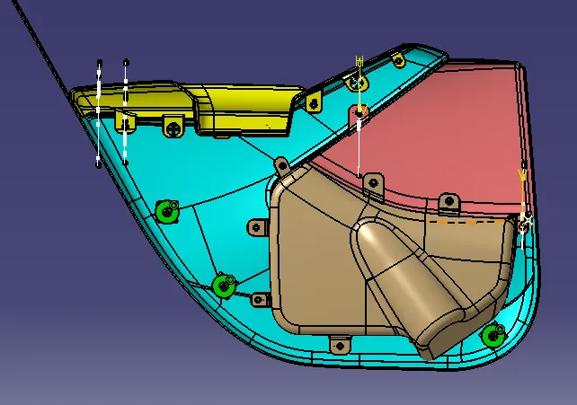
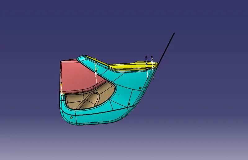
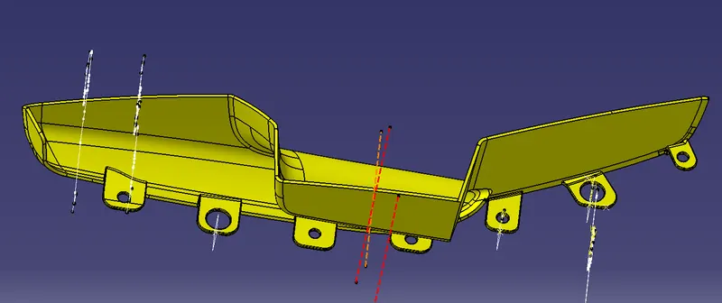
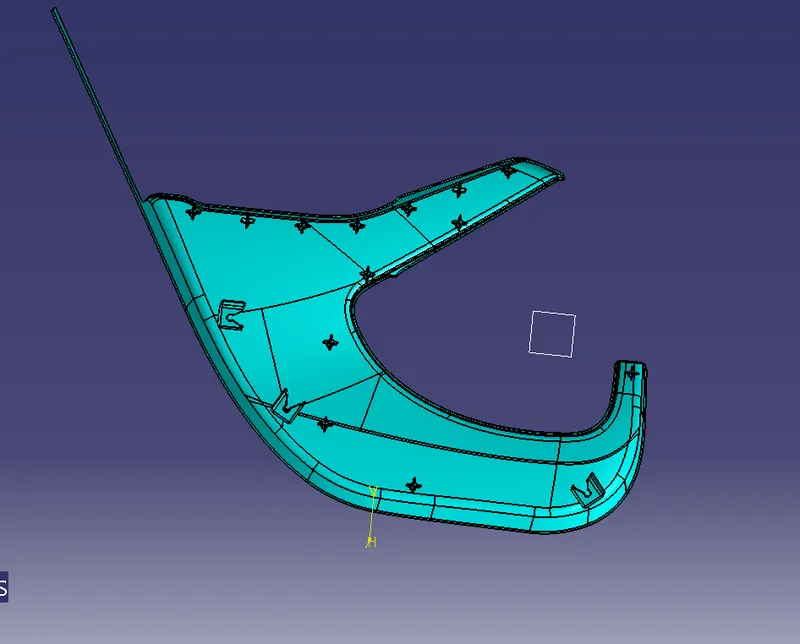
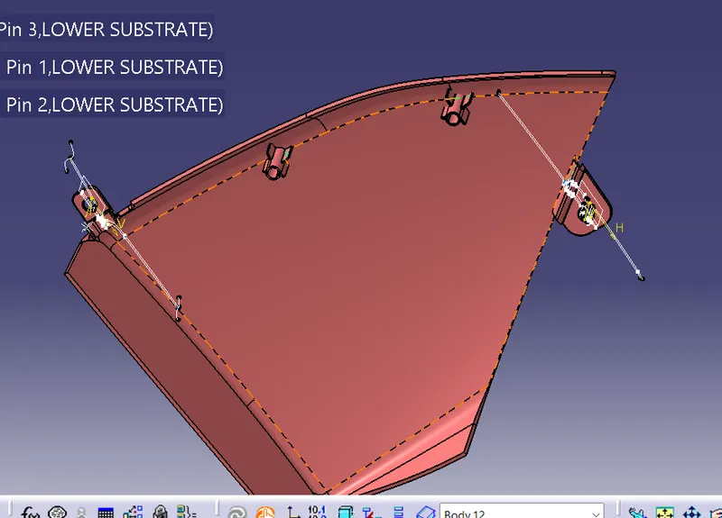
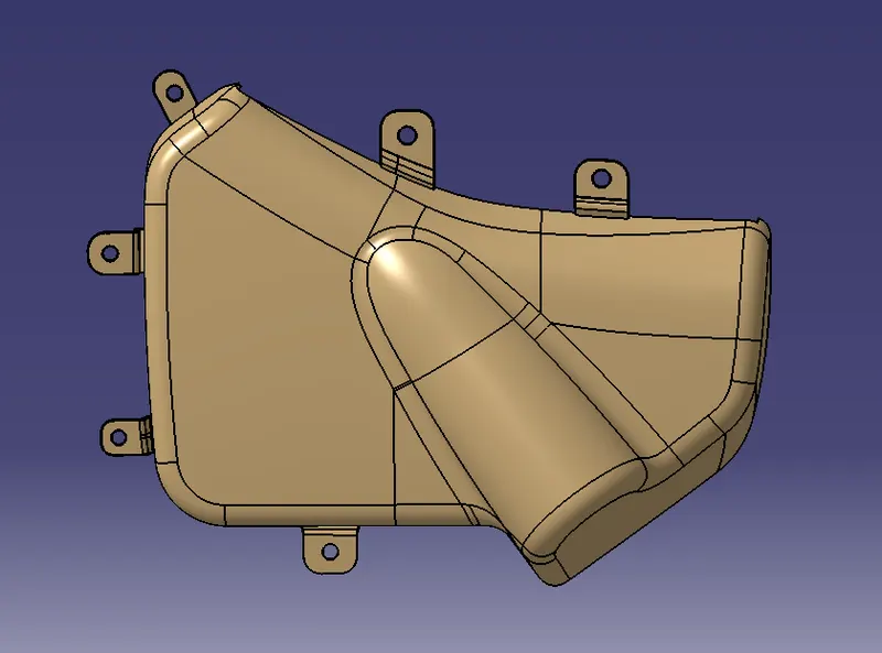
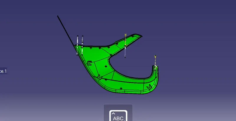
So we have given 4 class A surfaces of a door trim ,which are lower substrate, arm rest, bottle holder and map procket
STEPS TO FOLLOW
- STP file to product conversion
- Tooling Axis Creation
- Preaparation of class B and Class C Surface
- Closed surface creation
- B side engineering features creation
Step 1, STP file to cat product conversion
- The input is given as step file
- create as an individual part use sam management to save all the parts
- Assemble the parts before working on b side creation
Step 2, Tooling axis
- Since we have no master section given we can go with the point and direction method
- All the parts will have uniform tooling axis direction, else it ll be difficult to assemble, except arm rest all parts are good in y direction
- so in arm rest we ll keep a side core axis in y direction, main tooling axis in z direction
Step 3 and 4
- Create class b and c surface for all the parts as usual
- Bottom up assembly can be used for closed surface creation
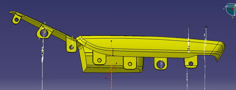
ARM REST
- Insert a new geometrical set for tooling axis , extrcat a surface use point and direction method to create the main tooling axis and side core axis in y and z direction respectively
- do the draft analysis make sure no problem with the class A
- Create a G. set for class B
- offset class A by 2.5mm , Modify the class B using split and spline to replicate class A ,do the extrapolation of class B
CLASS C
- Create a G set for class C
- Start the boundary creation, sweep operation, do the trim and join
- JOin the c With A surface
FINAL TRIM
- After getting A+c surface do the intersection with B and check whtether any gap is there or not
- Do the trim of B with A +c
CLOSED COMPONENT CREATION
After getting final surface do the closed surface tool in part worknench
- DO the DRAFT ANALYSIS
- draft anlysis i snot clearing properly, arm rest will be 2 sufaces but here we have given as a singler surface that is why draft analysis is not clearing with the tooling axis
CREATE THE OTHER 3 CLOSED COMPONENTS IN THE SIMILAR WAY
ENGINEERING FEATURES
HEAT STAKES
- Activate lower substrate part
- Insert a new geometrical set for Engineering features, insertr another in it For Heat stakes
- Now create a point and a plane at the base of the heat sytake , extract the edge for point
- Isolate the point and provide the coordinates
- Create a sketch on the plane by taking reference from master section
- isolate the reference
- extend it , close it provide the dimension
- create axis for shaft
- insert a new body for heat stake
- provide fillet at top edge of 0.25mm
- No needto provide the draft since it is directly provided in the mastersection
RIBS ON HEAT STAKES
- Create asketch on the same plane
- Take the refrence in sketch, isolate the refrence and extend it
- Provide dimension, isoconstrain it
- Insert a new body for the ribs
- Provide Pad of thickness 1.5mm
- To create the 2nd rib use the circular pattern tool
- do the draft OF 0.5 degree
- do the draft anlysis
- provide fillets
- Boolean operation of ribs with heat stakes
PLACEMENT OF OTHER HEAT STAKES
- Take the distance between centre part of heat stake with edge of the fillet nearby , it is 9.953
- dont take any refrence from solid , unhide the b surface
- Define heat stakes G .set and take the multiple extract of the edges of b surface
- Now we need to use parallel curve tool to offset the previous curve by 9.953
- now we need to create multiple points in equal distance, (50-75 mm)
- Using same procedure, create the curves and points for the placement of heat stakes and locator at the map procket and lower substrate
- Copy the heat stakes and use paste special to paste
- Use translate tool to translate the heat stakes
For creation of locator,
- insert a g. set for locator,
- Create a sketch f 15*15 mm
- insert a body and pad itfor 30mm, 1.5mm thickness
- Draft it for 0.5 degree
- provide the fillets at chamfer
- Copy the body and paste special, use the translate tool to translate
DOG HOUSE CREATION
- Take the extract of final trim of lower substrate
- create a point and a plane normal to tooling axis
- inser a new G. set for dog house
- create a sketch of 30*30 mm , provide 2nd limit of 2 mm
- decide which side is to be open
- insert a body , then pad
- provide draft to alll three walll except the front with 1.5 degree
- provide shell with 2.5mm as thickness
- Since dog house is an internal undercut we need a side core axis to manufacture
- Before creating the side core axis, do the draft anlysis for outer surface of dog house , whether it is clearing in 1.45 degree or not
- create the side core axis and do the draft analysis find out which surfaces need to provide the draft angle
- provide the inside draft angle of 0.5 degree
- check the draft analysis and make sure all inside surfaces are clearing or not
- Inorder to avoid sink marks we have to modify the dog house by providing coring
- Create a sketch on the same plane according to the design considerations
- insert a body , coring and pad it (3- 6mm), provide the 2nd limit of 2mm
- Provide draft for all the side wall of 1.5 degree with respect to the main tooling axis
- Time to remove the extruded part from thdog house
- then do the draft analysis , if not clearing do the draft of 0.5 degree with respect to side core axis
RIB CREATION DOG HOUSE
- Create a plane on the same point normal to tooling axis
- create a sketch , line , insert a body, pad it with 1.5mm thickness and some height
- draft w,r,t to tooling axis of 1.5 degree and w.r.t to side core with 0.5 degree
- provode fillets
- do boolean with dog house
FLANGE CREATION
- Flange shape will change w.r.t to placemenent , Height will change so we cant copy and paste it, we have to create ittt seperately
- there a re 8 -10 steps for creation of flanges
- Point and plane creation
- Create a plane paralle to the yz axis on the centre point of mastersection created in lower substrate
- isolate the point and change the definition to coordinates
- take the multiple extract of c sutface, since the flange will be created from the c surface of counter part
- only take mutiple extract from final trim
- take the intersection with the plane and the extract
- create a sketch
- sweep with profile as sketch and guiding curve as the multiple extract edgess of final trim
- do the trim and make solid using thick surfacess
- provide draft of o.5 degree
- provide fillets
- Now hole creation is left
- define the flange create a sketch of circle with dimeter 8.5 (7.5 +0.5+0.5)
- pad it and provide the draft, using boolean remove it
- provide the final fillets
- do the draft analsysis
ASSEMBLYING OF PUSH CLIPS ON THE DOG HOUSE
- Fix the lower substrate
- provide thecoincident constrain with the axis
- once agian provide the coincident constrain with the surfaces