Week 12- Final project
DOOR TRIM LOWER PANEL ( FINAL PROJECT) :
AIM : In this project we create the door trim panel components that is1) ARM REST
2) LOWER SUBSTRACT
3) MAP POCKET
4) BOTTLE HOLDER
we are providing the b side features like
dog houses, heat stakes ,4 way locators ,push pins, flanges and screw bosses
all these are providing by perfect draft angle of 0.5 degree
PROCEDURE FOLLOWED FOR CREATION OF THE COMPONENT
1) Analysis the input surface provided
2) Class a surface as an input surface
3) tooling axis creation
4) draft analysis for the class a surafce
5) class b surface creation
6) class c surafce creation
7) solid body or surface creation
8) Draft analysis for the solid surafce
9) creating the B side features
10) creating draft for b side features with respect to the part body
ARM REST
For the arm rest design the input class a surface is to check wheter the surafce have any open boundries use the boundry feature for checking there is any open patch or the surafce which we need to work on
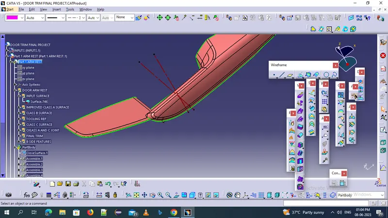
improve the given class a surface up to no patches are arived
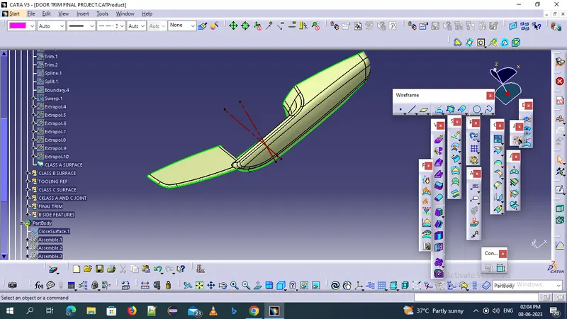
TOOLING AXIS CREATION :
We can create the tooling axis for the arm rest by using by section method . generating two lines and intersecting the line we got the tooling axis
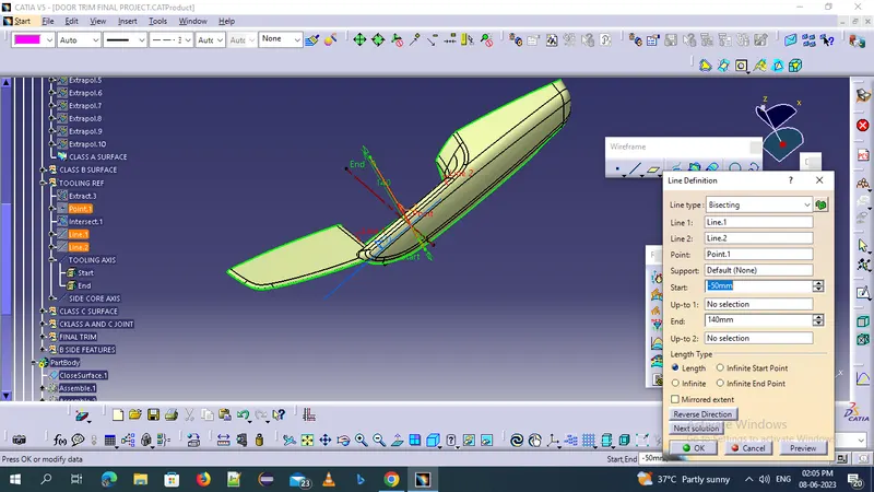
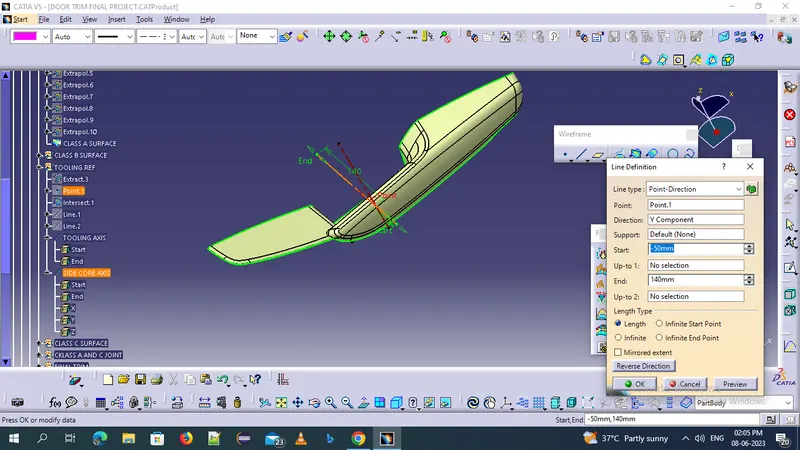
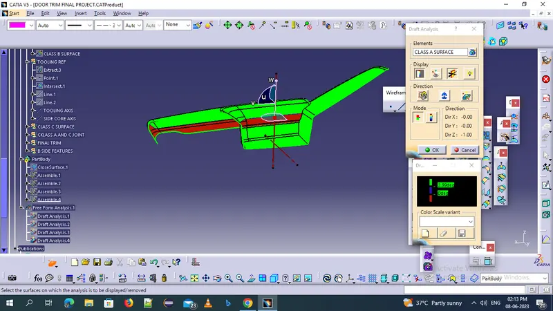
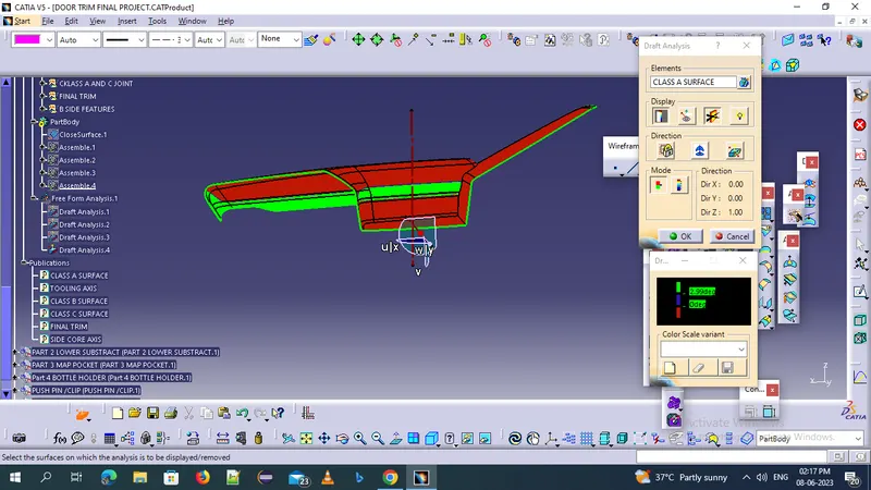
the tooling axis not clearing the draft of 3 degrees so we need to create an side core axis
CLASS B SURFACE CREATION :
Class b surafce is created by offseting the class a surface 2.5 mm thickness . extrapolating the class b edges to an extent to form the proper trim with the class a and c join
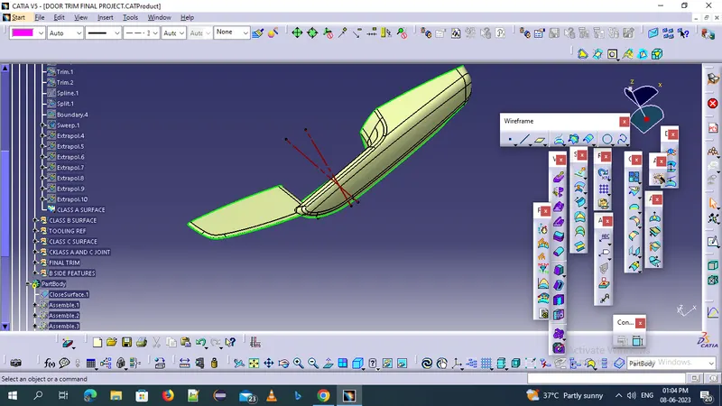
CLASS C SURAFCE CREATION
Class c surafce generation we use the class A surafce as an referance and follow the drfat with respect to the referance surface and mai tooling axis
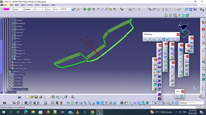
FINAL CLOSE SURAFCE CREATION
After creating the class b and class c surfaces join the class a and class c surface and trim the resultant with the class b surface then the surface is the final closed surfaces . then it is the closed surface of the plastic components with a thickness of 2.5 mm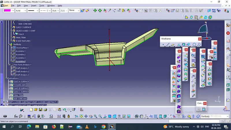
then createa new body and use the solid body feature to create the solid body out of it 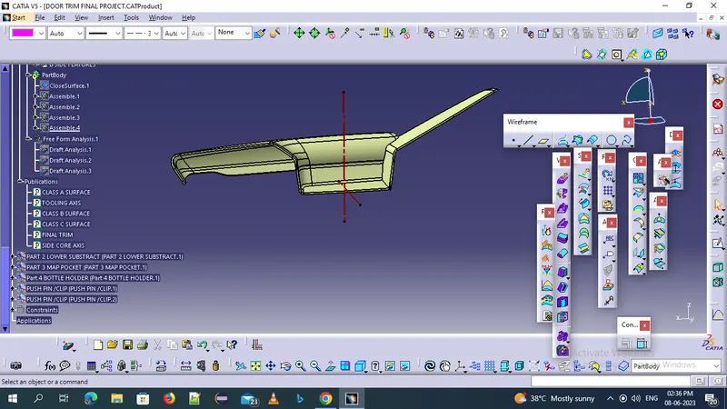
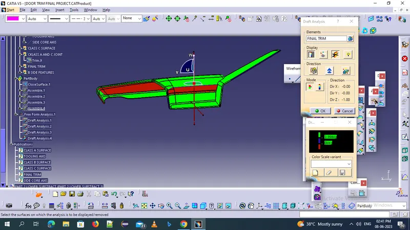
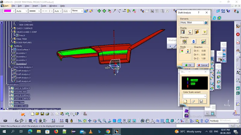
DRAFT ANALYSIS OF THE FINAL SOLID BODY
After creating the final closed body perform the draft analysis with a draft angle of 3 degrees .
2) LOWER SUBSTRACT :
Given class a surface containing the projection so there is no use so spliting that projection by creating liine on it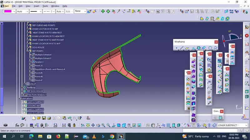
class a surface is 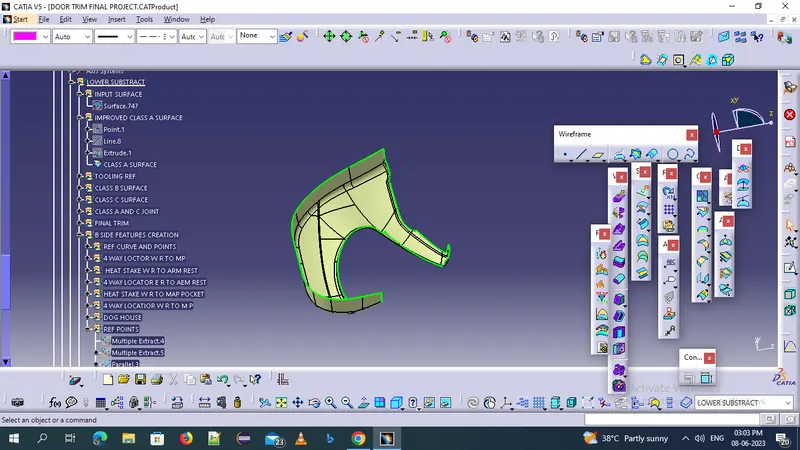
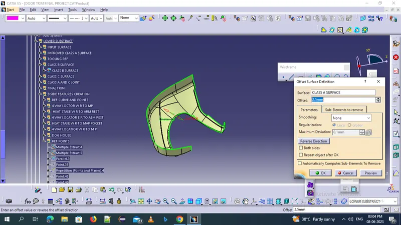
CLASS B SURFACE CREATION
class b surface is just created by using offset method
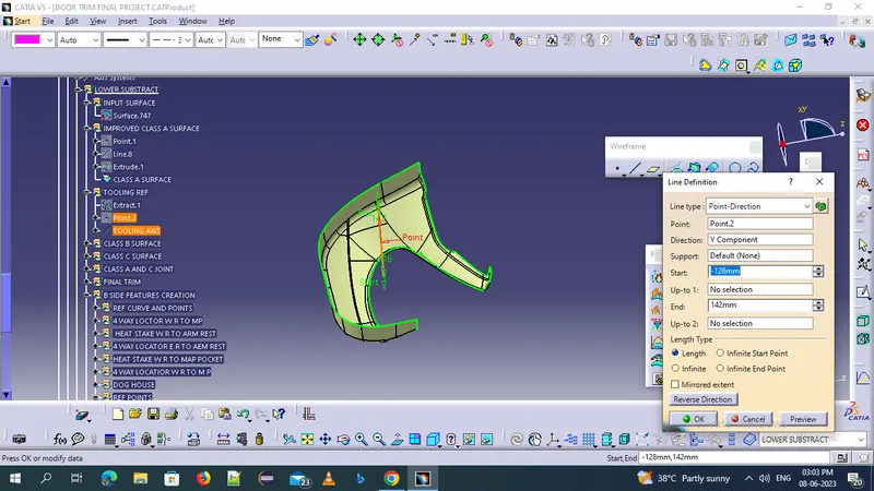
TOOLING AXIS CREATION :
Now create a point at the middle at o coordinates and create a line in point and direction method and create line in main tooling axis
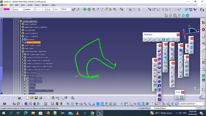
CLASS C SURAFCE CREATION :
the surface of the class csurface is parllel tho the tooling axis so use the sweep with resoect to the draft direction
 SS
SS
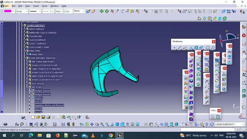
FINAL SOLID CREATION :
After joining the class a b and c surfaces for final trim we will create an solid body
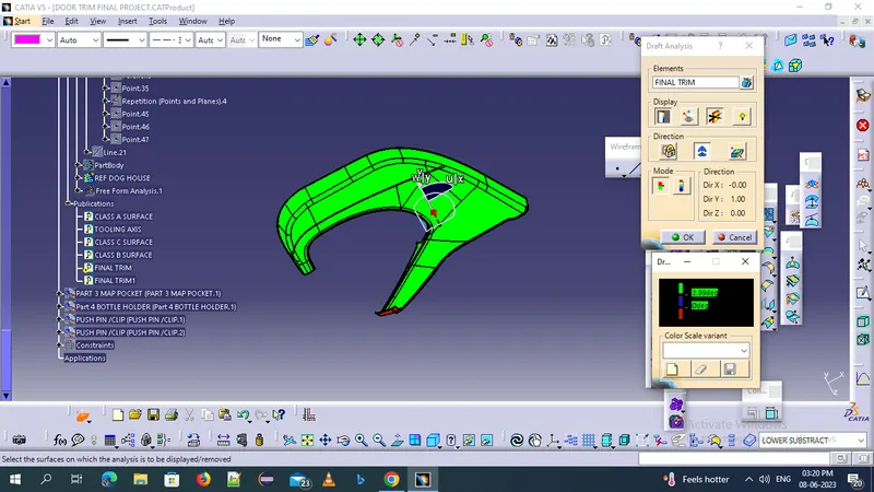
DRAFT ANALYSIS OF AN LOWER SUBSTRACT
MAP POCKET DESIGN :
the input surafce have no patches to improve the surace the given class a suraface is 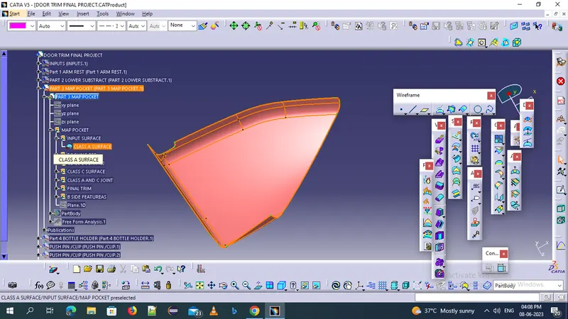
TOOLING AXIS CRAETOION :
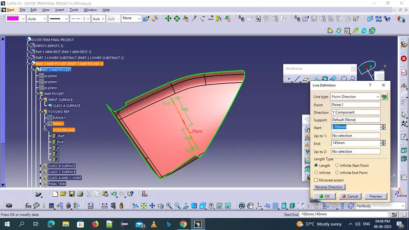
We extract the surface in y dirction at the 0 center point we generate the tooling axis of the map pocket
CLASS B SURACE CREATION
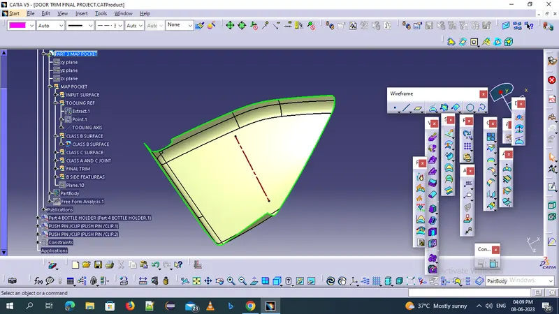
Create the class b surafce give 2.5 mm offset of the class a surafce extrapolate the class b edges to form the perfcet trim with class a and c joint
CLASS C SURAFCE CREATION :
Create the class c surface betwwen the class a and the class b surfaces create with help of sweep option with draft of 3 degrees along the tooling axis direction 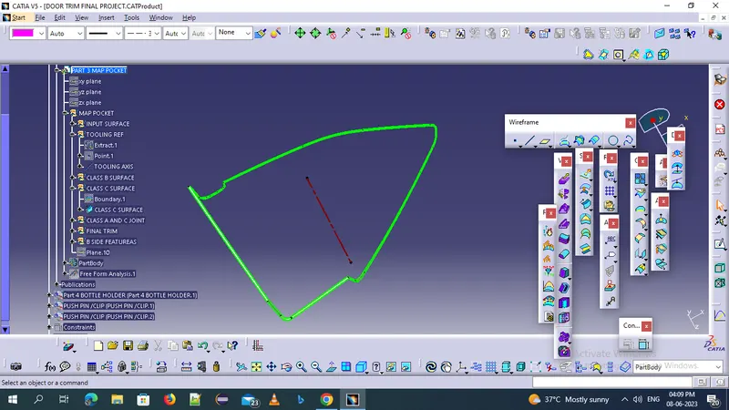
FINAL SURFACE CREATION :
Once all the surfaces created that is class a b and c surafaces then join the class a and c surafce then trim with the class b suraface the final solid body is 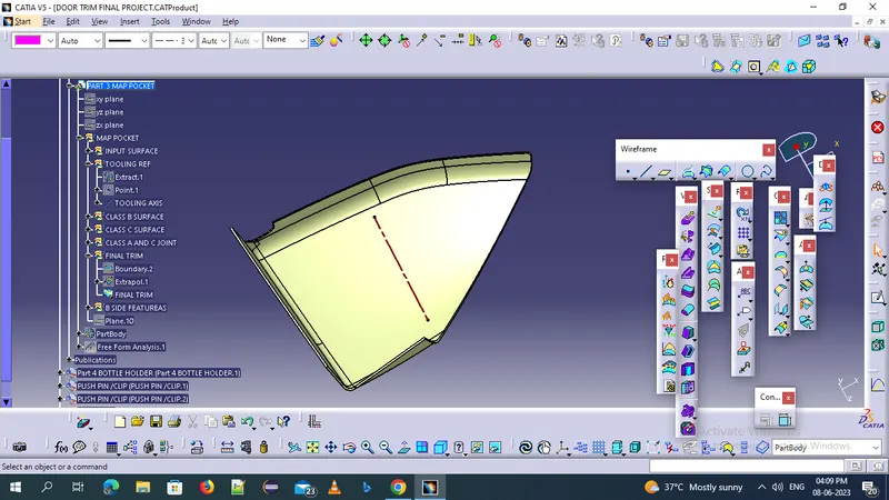
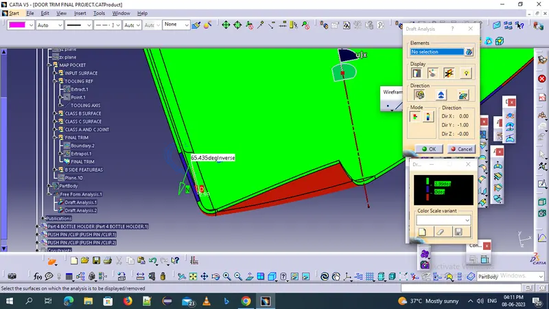
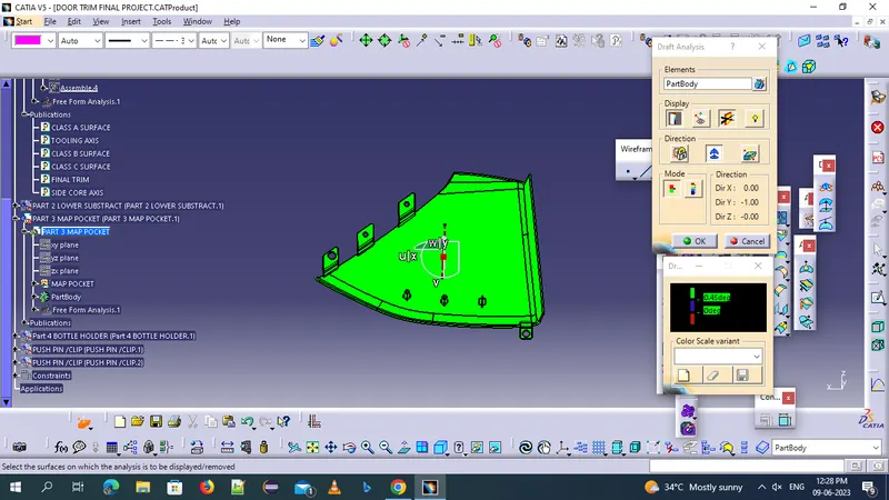
DRAFT ANALYSIS OF MAP POCKET :
THE draft analysis with a draft angle of 3 degrees on the solid body 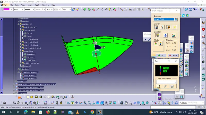
almost all surfaces are clearing with draft of 3 degree but some ares not due to class a surface not clered properlly
BOTTLE HOLDER DESIGN :
The input surface provided for the bottle holder is
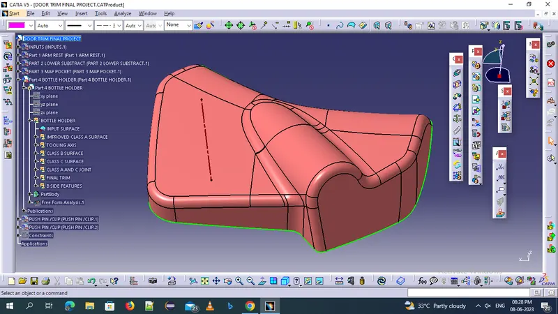
some patches are arived in given bottle holder so now improve the surface is
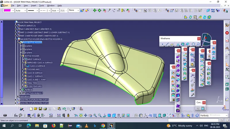
TOOLING AXIS CREATION :
Inthe case of the bottle holder use the flat surface and extract the surafce and create a point at the 0 coordinates and use the point-direction to create a tooling axis
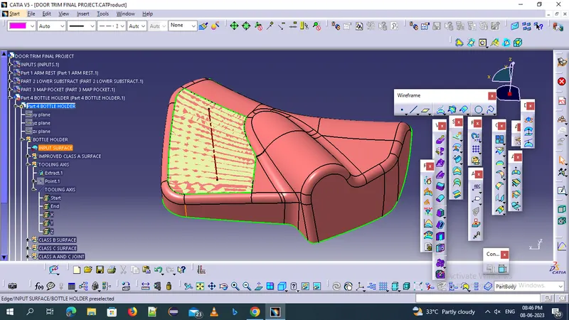
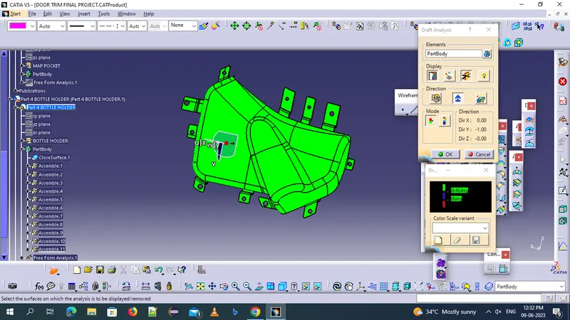
DRAFT ANALYSIS OF AN B H:
Perform the drfat analysis of an class A surface with draft angle 3 degrees the result was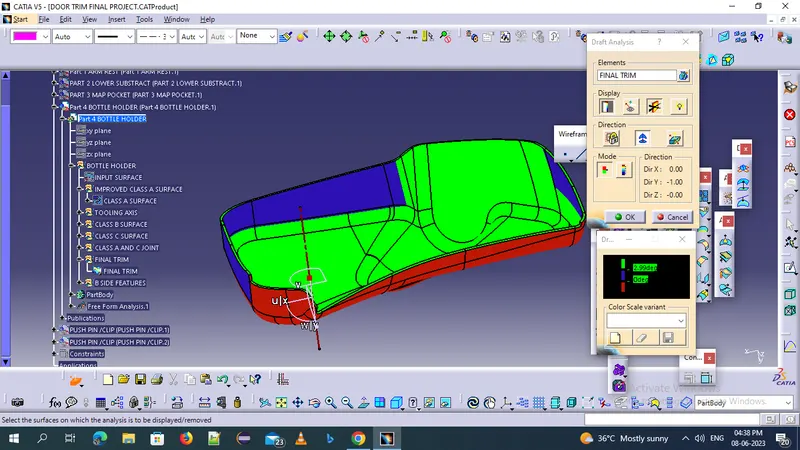
the class a surface was not clearing the surface so we need to infom this to class A team because they given surface is not an apporiate
CLASS B SURFACE CREATION :
Now offset the class b surface to 2.5 mm following the master section
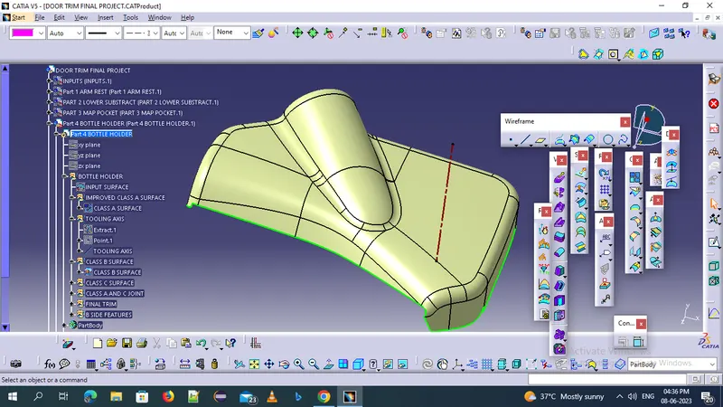
CLASS C SURFACE CREATION :
create the class c surface with respect to the class a surface and sweep the boundry with tooling axis .so provide a 3 dgrees draft direction making the direction ofthe draft
FINAL SURFACE CREATION :
Once the closed surface is created go through the part workbench and use the solid surface feature to generate the solid body out of it
DRAFT ANGLE ANALYIS :
As shown in class a surface the same surface not getting clear so we need to inform class a team to create a class a surface properlly
B SIDE ATTACHMENT FEATURES
1 DOG HOUSE
2 RIBS
3 SCREW BOSSES
4 FLANGES
5 HEAT STAKES
LOWER SUBSTRACT ATTACHMENT FRATURES :
Based on the master sections provided for the input surface of the lower substracte it indicates theat the heat stakes are positioned on the surface following the master sections we need to create the heat stakes on the lower substract b side
1 height we need to follow the master section
2 draft provided on the outer and inner face an angle of 0.5 degrees
3 pad the sketch with a height respresent in the master sections taking reference as tooling dirction
4 create the ribs for the additional support
ribs design
1 locating and aresting the components of an assembly
2 providing alignment in mating parts
3 acts as a guides or stops in mechanisms
4 draft 0.5 degree per side minimum and max up to 1.5 degree
5 thickness of ribs 40 - 50% of wall thickness
height of ribs is less than 5 times the wall thickness
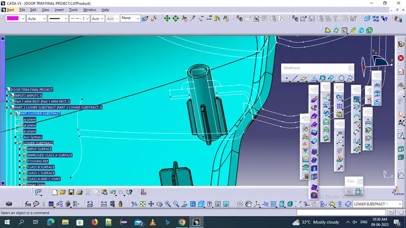
apply the fillets of 0.25 mm minimum on all the shapes edges and you also apply chamfer for the tip of the ribs and apply the boolena operation of union trim to combine ribs and the heat stakes
the distance between the heat stakes is 50 to 100 mm
LOCATORS :
The gap between flange and the locator should be range between 0.5 and 1 mm
the design rules as the ribs and locator there are two types of locators but we are using 4 way locators
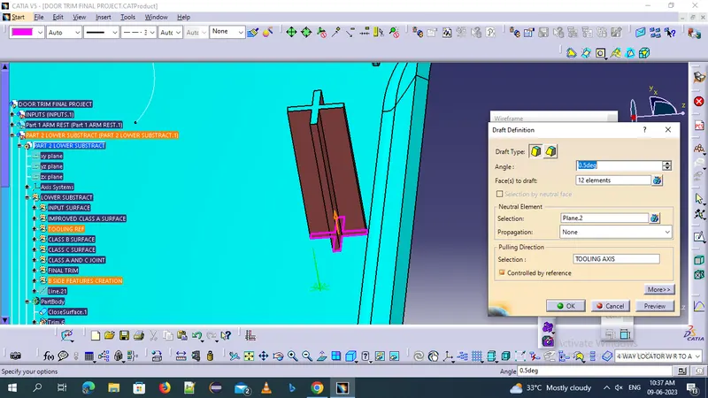
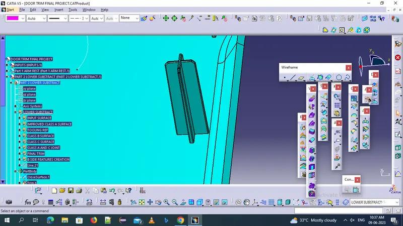
D0G HOUSE CREATION AND DESIGN
dog house is an engineering feature used in plastic trim design which helps to remove sink marks formed on class a surface while creating attachment feature on class b surface .dog house is a supporting feature other feature like locators heat stakes pushpins
hear i has used 15*15 dog house padded to a height of 30 mm
apply the shell of 2.5mm to make a cavity in the dog house
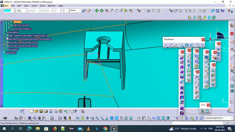
rib cage for providing the additional support for the dog house we create a rib cage with two ribs of 1 mm thickness and providing a draft of 0.5 deg with respect to the side core tooling axis
at the top surface provided a cutout to provide the room for the pushclip to provide the room for the pushclip to positrion it in the top of the dog house
PUSH PINS
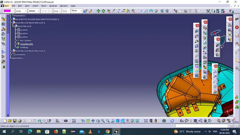
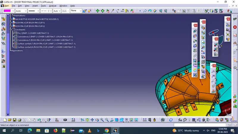
Push pins are used for joining one compponent to another these are basically attached to the doghouse for creating the push pins the following reference was taken for dimensions
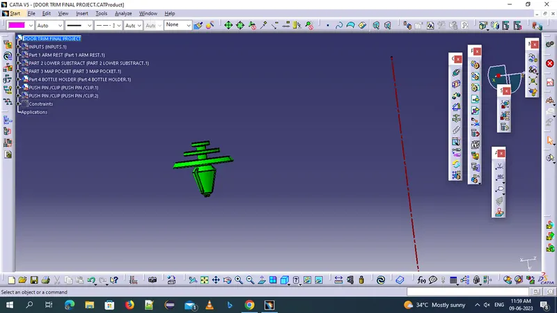
the draft analysis on the outer edges of 1.5 deg draft is
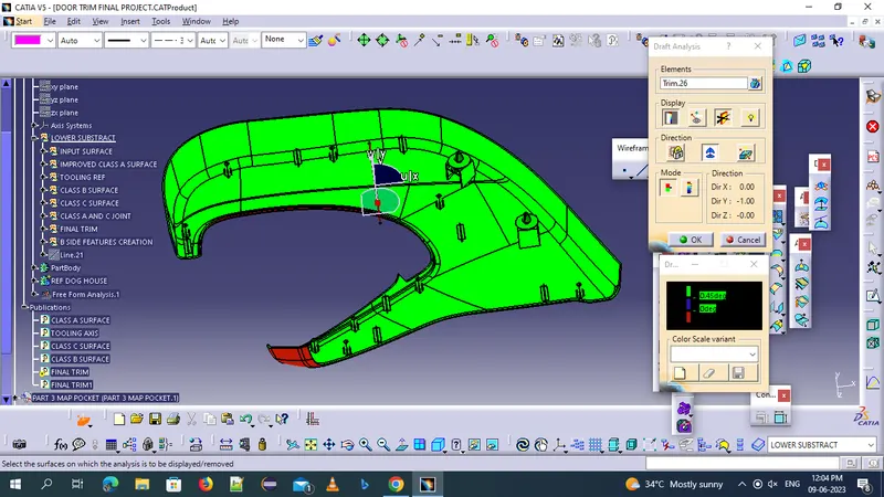
B SIDE ATTACHMENT ON THE DOOR ARM REST
FLANGES
Flanges are the joining features that helps to assemble different components the mastersections was used to make flanges ,after creating one flange point to point translation is used to translate the flanges we need to provide a draft of 0.5deg for the flanges the gap between flanges should be 50-100mm .boolean operations were used to add attachment features into add attachment features into closed body
soame procedure for flange draft
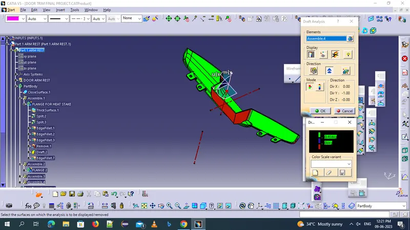
flanges are created c surface of the body
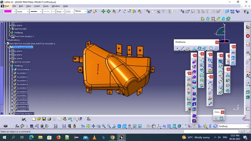
B SIDE ATACHMENTS ON BOTTLE HOLDER
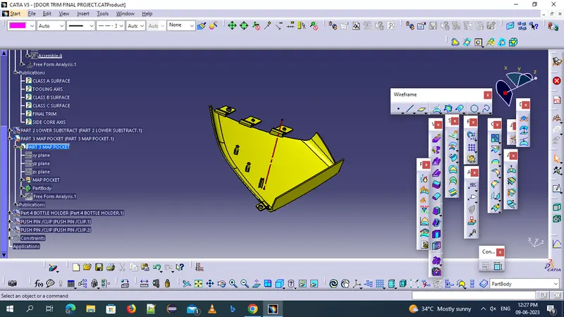
DRAFT ANALYSIS OF AN MAP POCKET
B SIDE FEATURES OF AN BOTTLE HOLDER
With same dimentions and coordintes we need to create an flanges for an heat stakes and loctors on bottle holder
draft analysis for bottle holder
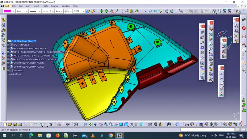
FINAL OUTOUT OF AN DOOR TRIM PANEL IS
CONCLUSION :
The design of an the automotive door trim panel from a class a surface to a closed part body with all the necessary attachments features by following all the design rules using catia v5 ia done successfully and all the required cat product files are attached
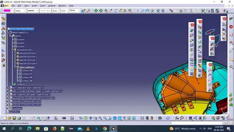
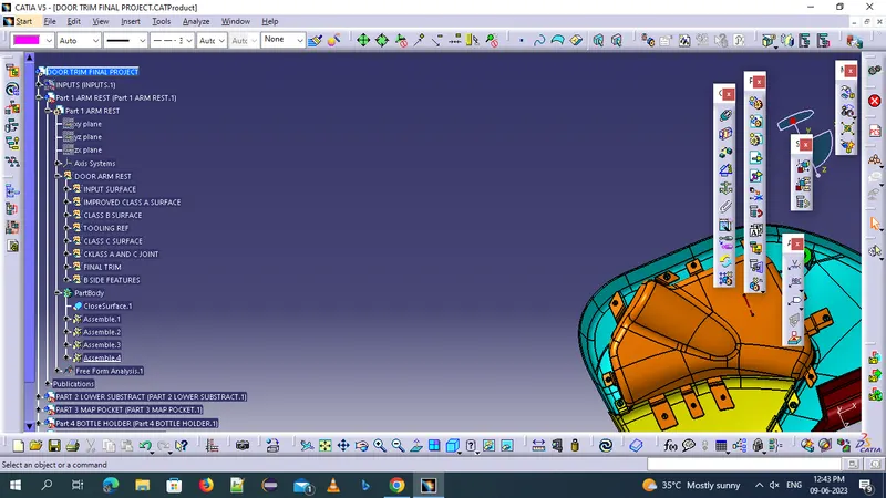
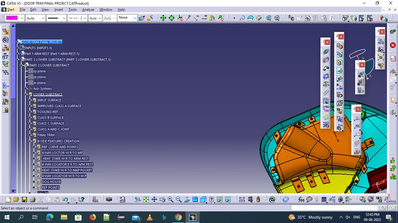
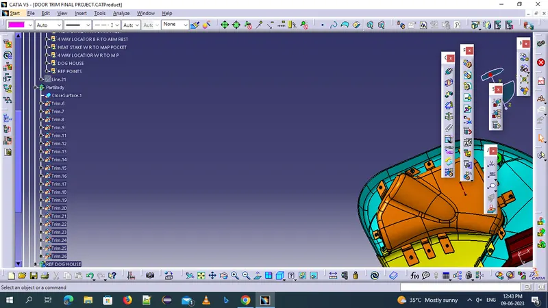
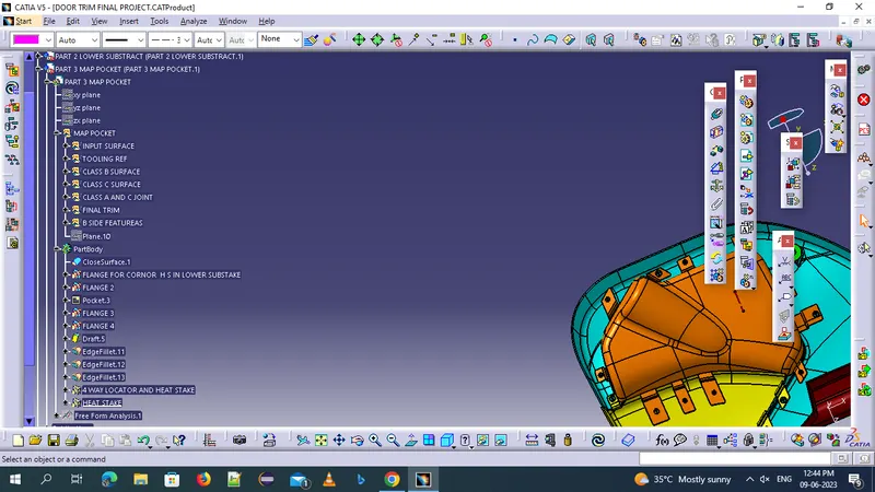
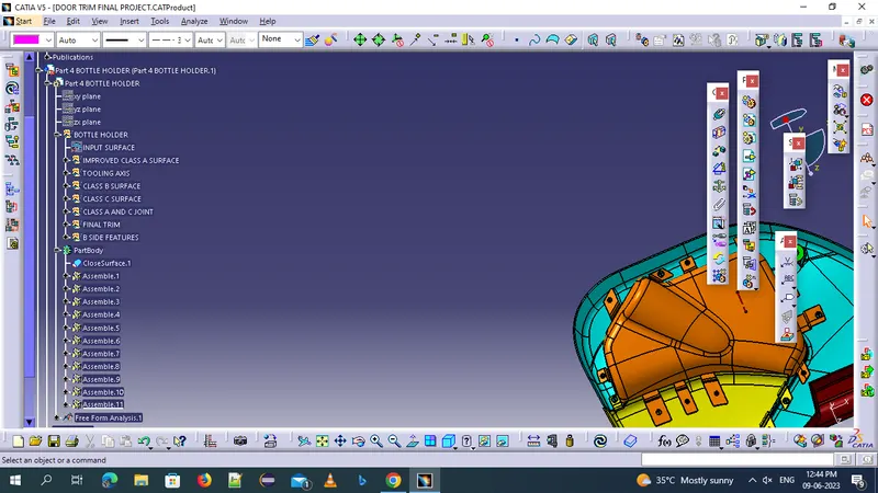
THE TREE STRUCTUR USED AS
DOOR ARM REST
LOWER SUBSTRACT
MAP POCKET
BOTTLE HOLDER
PUSH PINS