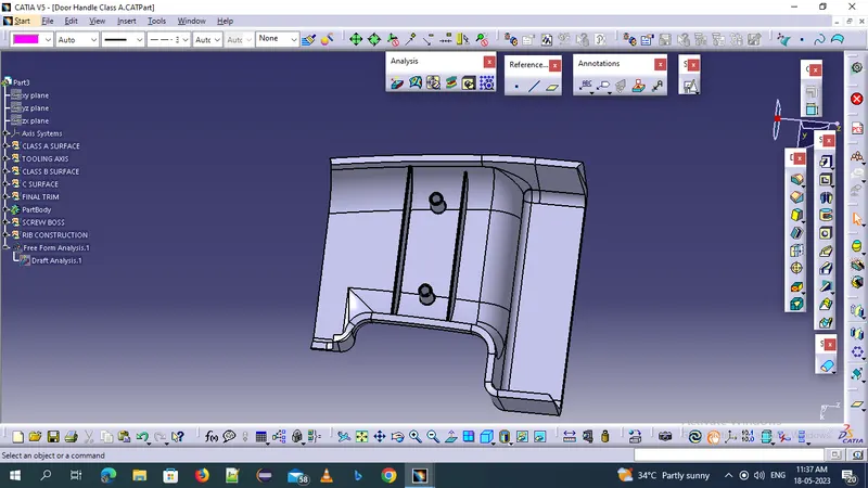
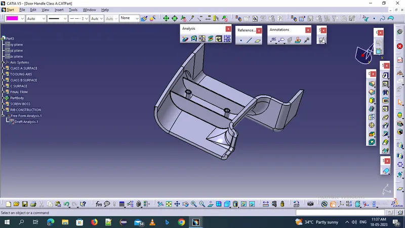
Week 10 - Challenge 1- Attachment Feature Creation (Ribs & Screw Boss)
RIB AND BOSS DESIGN :- Rib and boss construction for an given refer to the process of creating protrusions or recesses on a part design. ribs are thin, elongated protrusions that are typically used to provide additional strength and support to a part on the other hand bosses are raised areas or protrusions used for various purposes, such as providing mounting points for screws or accommodating inserts.
- open the given cat part and give the thickness of the part at reqired dia
- ensure that you are in possition sketcher
- choose the plane or surface where u want to create the rib and boos feature you can select new one or exixting plane or create a new plane
- select the approprite sketching tool such as lines , circles or arcs to define the outline of the rib or boss feature.
- for us given draft minimum 0.5 degree
- W =0.4*t
- rib tip is equal to 0.75mm
- rib fillet thickness is 0.25 max
- apply any nessery geometric constructions or diamentions to aaccurately define the size and position of the rib and boss.
- exit the sketcher mode and enter the part design
- select the pad and pocket commands for the toolbar,dwpending on whether you want to create a rib or boss respectively
- if needed you can modify the rib and boss feature by selecting it and using commands like edit ,modify,dress up to add chamfers drafts or other modification.
- the steps are repeated for create multiple ribs or bosses on the part.