Week 12- Final project
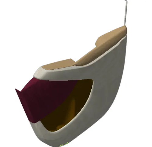
AIM: To develop Door Trim Panel through class A surface with master section.
Objective: In this project, I have to design Door Trim Panel through given class A surface with master section considering all the design rules using different tool in CATIA V5. Ensure proper tree structure and all the sketch should be ISO constrained.
Constraints:
- No change in Class A are allowed but if any discountinuity found then improved class A surface and tell head of department.
- Part thickness can't deviate by more than +- 30%
- All design rules should be strictly followed.
- All surfaces should be closed before converting to solid
- All faces should meet the allowed draft requirements.
Introduction: Door Trim is an interior component attached to the inner side of the door. This product does more than merely improve the appearance of the vehicle interior. Rather, it is a vital module component that creates a more comfortable interior by providing a variety of design specifications regarding safety, aesthetics and functionality.
Design Methodology:
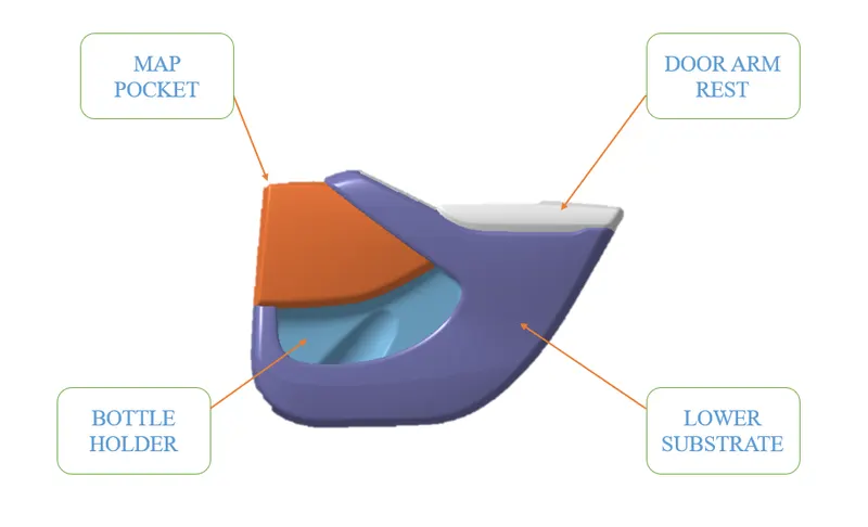
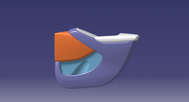
For this project, I have to design four parts of the door trim using the master sections provided, namely
- Door Arm Rest
- Lower Substrate
- Map Pocket
- Bottle Holder
- And attach engineering features through master section.
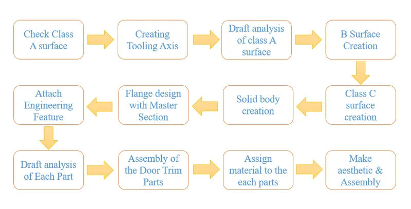
We can see in below figure also,
Methodology
TERM AND DEFINITIONS:
Class A Surface:
In autoomobile industry various team works in various components, a car for example is not entirely designed by a single designer. There are many teams among which the task of making various components is distributed and this is followed for every department of the industry. In the project, we are given class-A surface which is designed in other software like Autodesk Alias by a class-A designer. This is the styling surface which provides the aesthetic feature of the component. A designer starts the component design from Class-A Surface.
Class B Surface:
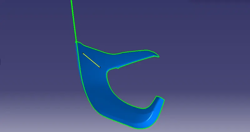
Class B surface is obtained by offsetting the class A surface by the component thickness value. This B Surface contains all the engineering features of the component.
Class C Surface:
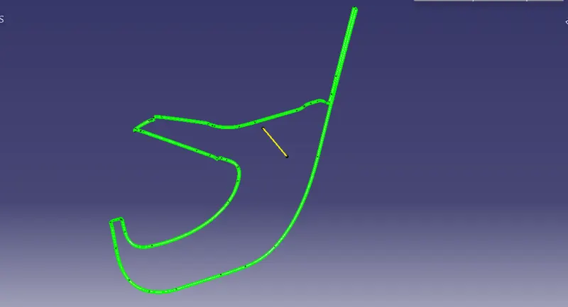
Class C surface is created along with the reference surface or the tooling direction of the component and join with class A surface after then connect with class B surface.
Tooling Axis:
Tooling axis is the direction in which the 2 halves of the mould (core and cavity) opens or closes, or the direction in which the part is release from the mould.
Draft Angle:
Draft angles are measured from the Tooling axis of the part. For mould designs where one metal mould component make direct contact with another, a minimum of 3 degree draft is required to ensure that the mould can separate properly.
Plastic parts that are made by the forming , casting, pressing or even molding, require a draft angle at their side walls. Draft angles are the degree of taper that is incorporated into the side wall and cores of the die cast tool to aid in the removal of the part. Primarily, they function to reduce the friction between the part and the tool as it is ejected. Without draft angles, parts can be stripped, dented, or get stuck in the tool.
Draft Analysis:
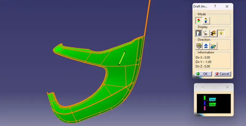
Draft analysis measures the draft angle on multiple surfaces of the part along the tooling axis to check if the surfaces have the minimum required draft angle for it to be mouled properly or if not, it creates problem while ejecting from the mold. This analysis tells us whether our component will be safely ejected in the tooling axis that we have provided. Some components require side core where there are undercuts, holes or projection on the side walls. we have to make sure that our entire model is in green colour which means it is clearing the analysis. so we have to run analysis for class A surface, solid model and other B-side features as every single component, regardless of its size should be ejected safely from the core.
Parting Line:
A 'Parting Line' is the line of seperation on the plastic part where the two halves of the plastic injection mold meet. The line actually indicates the parting 'Plane' that passes through the part. Within more basic plastic part design plans this plane can be simple, flat surface, but it is often a complex form that traces the perimeter of the part around the various features.
Ribs:
Ribs are thin wall like structures that add support and rigidity to injection moulded parts. They are thinner than primary walls and are used to support these walls, as well as bosses, by running perpendicular to these structures. Ribs are often used to replace thick wall sections to avoid sink marks, wrap and voids.
Dog House:
Dog house is an engineering feature used in plastic trim design. These are used as supporting feature and other engineering features such as bosses, locators etc are mounted on them to increase their strength. Dog houses require a slider for moulding and are subjected to draft analysis along the slider axis to prevent breakage during ejection from mould cavity.
Heat Stakes:
Heat staking technology is quite simple in concept. Whenever two or more components need to be attached to one another, and at least one is made of a thermoplastic, a combination of heat and pressure can be used to reform the plastic to the many shapes or profiles to retain or join the parts together.
This creates a solid, hardware-free bond that uses the plastic’s inherent strength to keep the finished assembly together.
2-way & 4-way locators:
A 2-way locating pin restricts motion along 1 axis (or 2 degrees of Freedom) like a round pin in a slot. Likewise, a 4-way pin restricts 4 degrees of freedom along 2 axes of an object. A round locating pin located concentrically in a hole is a common application of a 4-way pin, and helps to further secure the piece.
Design Process:
- For all the parts the class A surface is checked for surface abnormalities, if found ok then the plastic component design is started else the class A surface is sent back to the product design team for correcting it.
- Tooling and slide core axis (if required) is created for each of the part and draft analysis of the class A surface is done.
- The class B surface is then created by offsetting the class A surface by the component thickness value which is measured from the master sections that are provided.
- C surface is then created by extracting the edges of the class A surfaces and sweeping them with respect to of the tooling axis or the refernce surfaces.
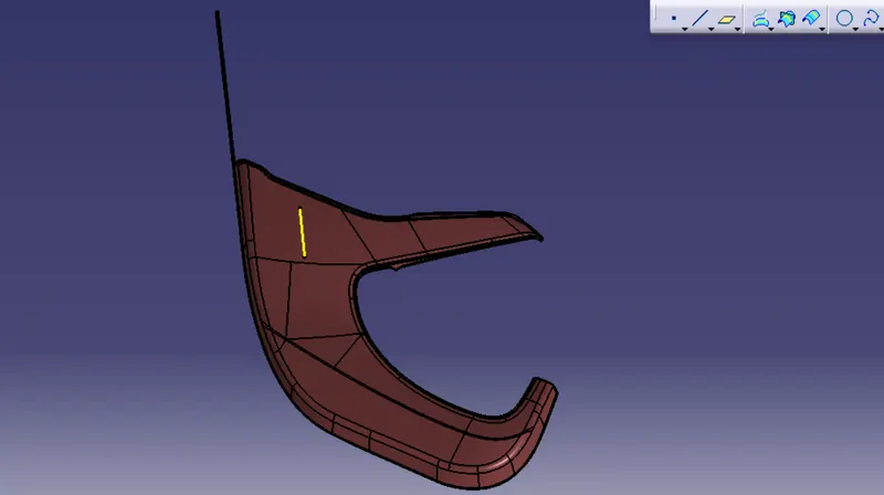
- The A, B and C surfaces are then trimmed and joined to create a closed body.
- Flanges and other attachment features are then design on the closed body following the master sections.
- Draft analysis is then done on the final body along their respective tooling axis to check the draft provided in the surfaces for proper removal of the part from the moulds.
- Once all the part design are finalized they are assembled along the Push Pins which are situated right above the Dog House roof on the Lower Substrate.
INPUT CLASS A SURFACE:
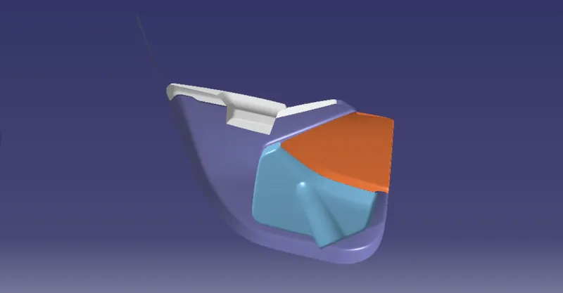
Class A surface
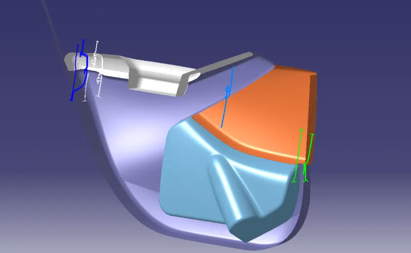
Master Section sketches
DOOR ARM REST:
Procedure
- Import class A surface
- Check boundry abnormality
- Create tooling axis
- Draft analysis of class A
- Create class B surface
- Create class C surface
- Joined Class A,B & C surface and make close surface
- Make it solid body
- Add flanges with master section
- Analysis final body draft analysis
Class A surface (Given)
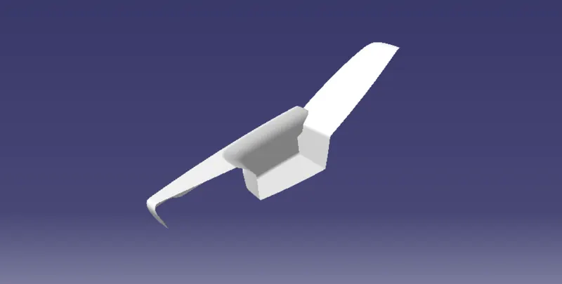
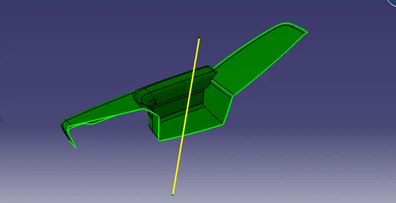
Improved class A surface
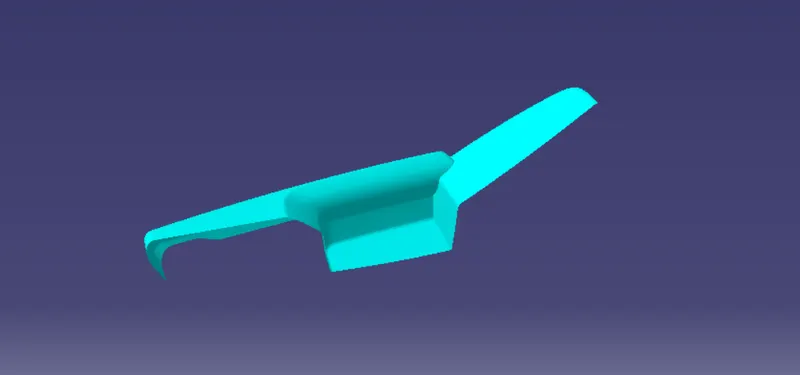
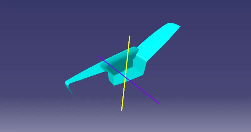
Tooling direction (Here i create two tooling axis becouse we can clearly see that it has core side so for that create core tool axis)
First we have to observe and study the class A surface to create the "Tooling Axis" for the component, and for the above given ARM REST. Here i use bisecting method. Once the bisecting line get, rest of the line make construction line. Now analyse tooling axis by analysing draft and class A surface making an angle direction inbetween 0-3 degree by draft analysis.
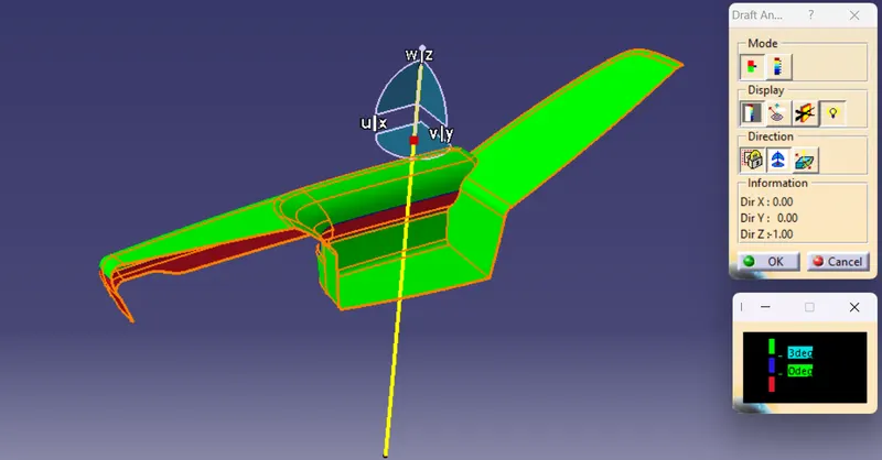
Draft analysis along with tooling axis (here it shows some part is in red colour becouse of parallel to the tooling axis and curveness)
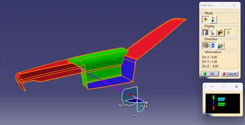
Draft analysis along with side core tooling axis
Class B Surface
To create the class-B surfeace, I will go through the direct offset method becouse here the given ARM REST surface are very difficult to find out where to start class-B surface so to do that we have to directly offset it upto desired thickness (2.5mm) and then we will go through, like some part are missing in offset surface. So that surface we have to fill by using extraction, untrimmed, extrapolation, trimming, joinning, sweep tool in surface design workbench etc.
Class C Surface
It is the combination of Class A, Class B and Class C surfaces. To create a class C surface, I used the sweep command by considering the outer boundary of the class A surface. In the sweep command, go to the 'line' command in the 'profile' block and the subtype is 'with reference surface'. Now select the outer boundary and reference surface, give 90 deg in the angle and select the direction to sweep, in this condition the class B surface is under the class A surface so select the inside arrow to sweep. Now I joined all the sweeped surfaces by using the 'join' command and then I trimmed the Class A, Class B and Class C surfaces to make a closed surface, to make a Solid body.
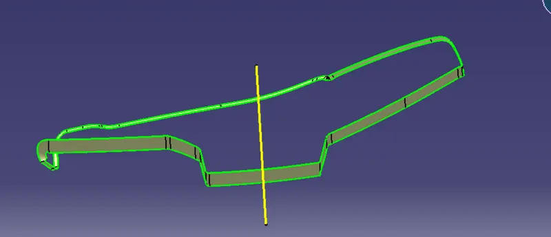
Joined Class A&C
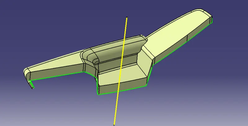
Close Surface (trimmed with class B surface and joined class A&C surface)
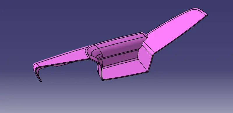
Solid body
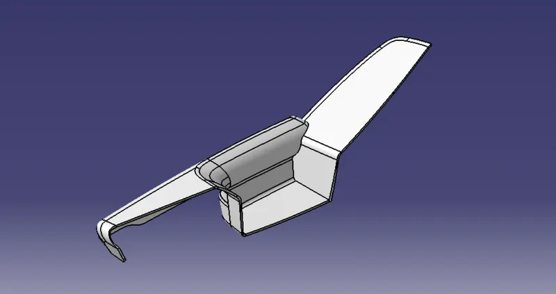
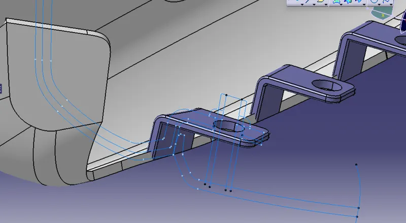
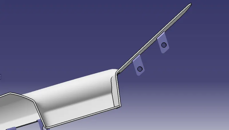
Flanges on the door arm rest for attachment with the lower substrate
Lower flanges
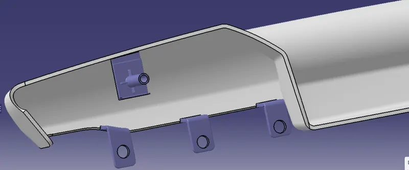
Final outlook of Door ARM REST
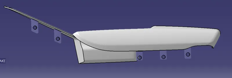
Arm Rest final solid body draft analysis along tooling axis
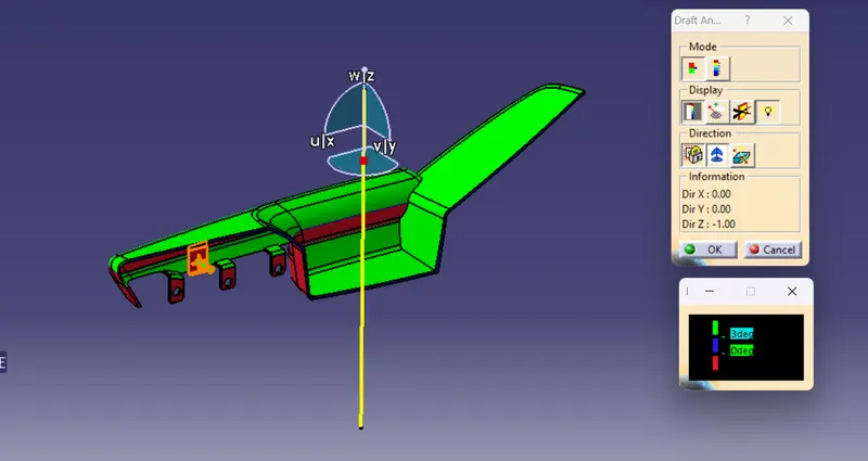
Arm Rest final solid body draft analysis along with side core tooling axis
LOWER SUBSTRATE:
Procedure
- Import class A surface
- Check boundry abnormality
- Create tooling axis
- Draft analysis of class A
- Create class B surface
- Create class C surface
- Joined Class A,B & C surface and make close surface
- Make it solid body
- Add flanges with master section
- Analysis final body draft analysis
There are no surface abnormality in lower substrate
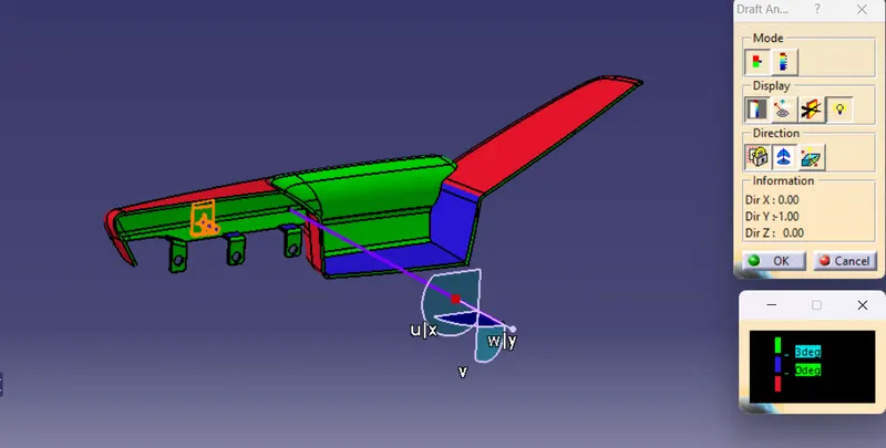
Tooling Direction (Tooling axis along with y dirn and side tooling axis for doghouse)
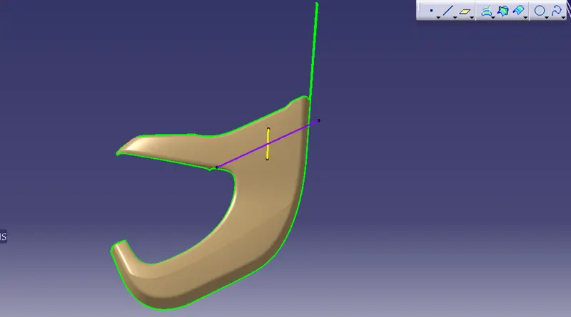
Draft analysis of class A surface
Class B Surface (Offset value 2.5mm)
Class C Surface
Joined Class A & C and then Trim with class B surface to make close body
Solid body of lower substrate
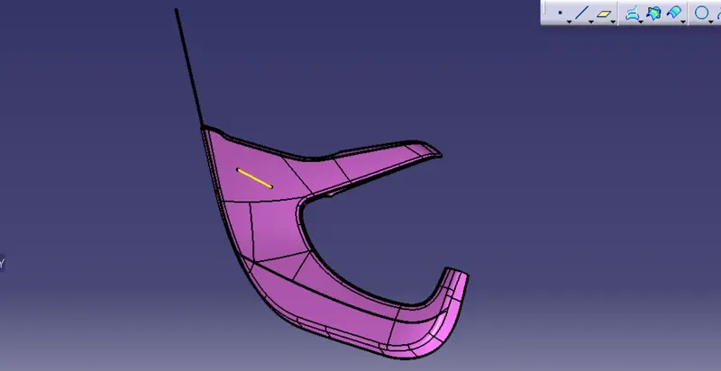
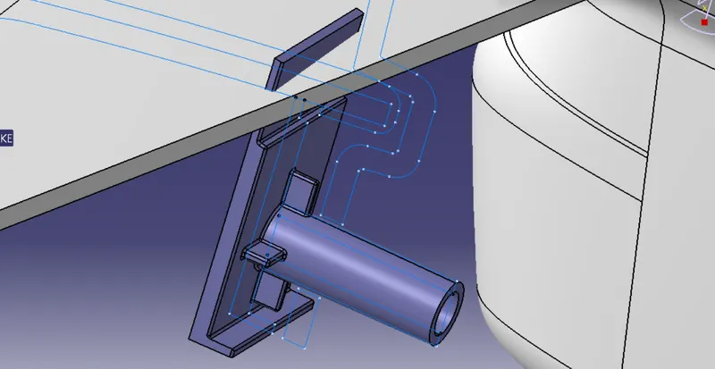
Now attach engineering feature like Heat Stake, Locators, Ribs and Dog house
Heat Stake and Locators
Here we create heat stake through master section and this bosses spread over all lower substrate
NOTE: Keeping in mind 50mm minimum gap between two heat stake or locators
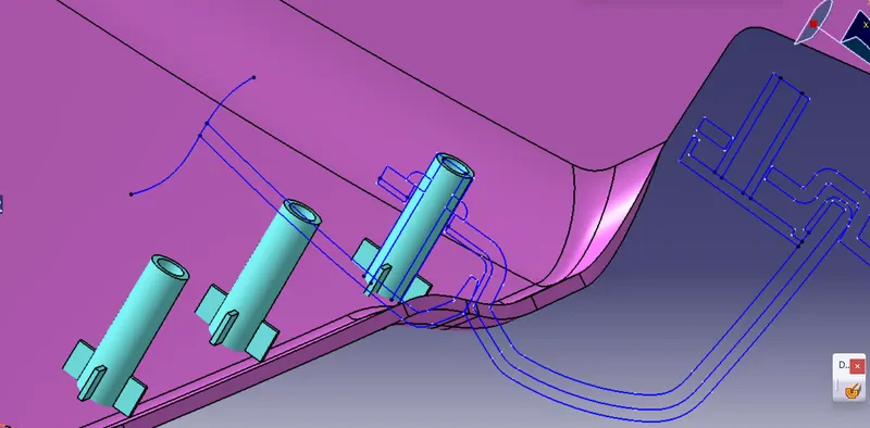
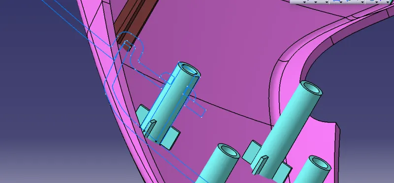
Locators
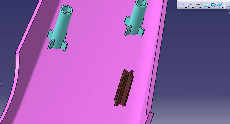
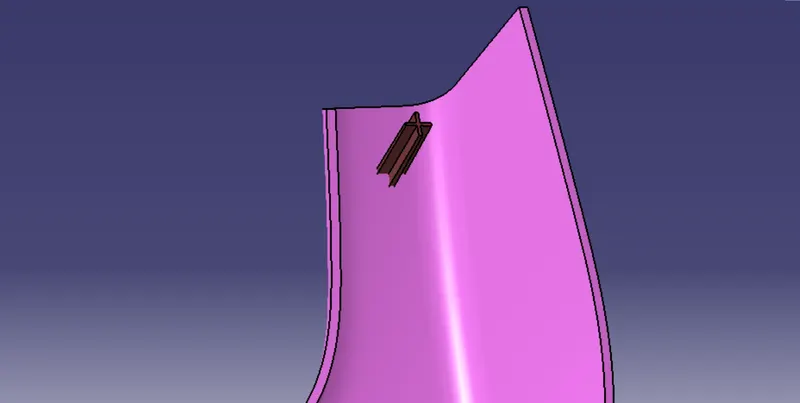
Now attach ribs at the wall of the lower substrate (Keeping in mind minimum 50mm gap between two ribs)
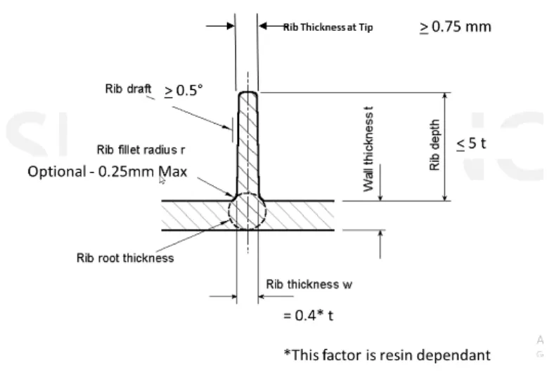
Design rules for Rib Creation
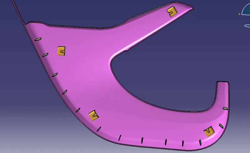
Attach DOG HOUSE at Lower Substrate
Design rules for DOG HOUSE Creation
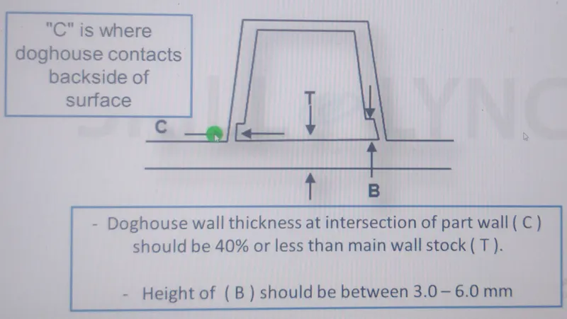
DOG HOUSE
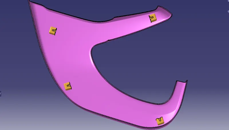
Assembly of engineering feature as we can see in below figure
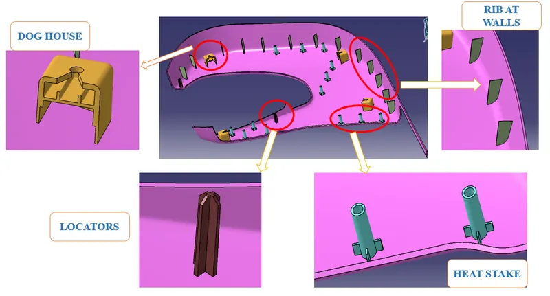
The 4 way locators, ribs and dog houses were created using design guidelines, while the heat stakes are created using the master section.
Draft analysis of final body along tooling axis
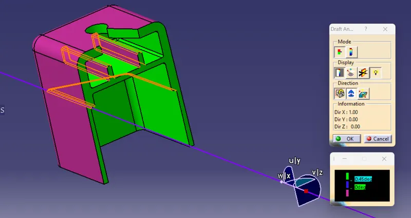
Here we can see that all are in green and blue colour, green colour shows draft provided at the lower substrate is 3 degree and blue colour shows draft angle shows less than 3 degree but it's an engineering feature so for that we give 0.5 draft angle when we provide 0.45 degree reference it shows all are in green colour with engineering feature (see below figure).
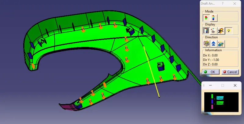
When we provide Draft angle 0.45 degree
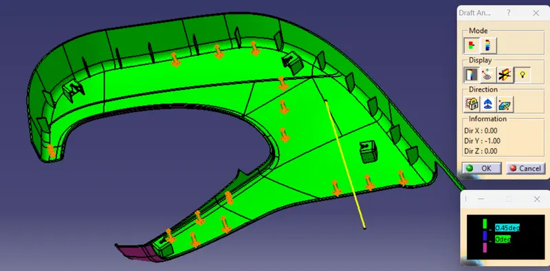
Draft angle of DOG HOUSE (Draft angle provide 0.45 degree) along with side core tooling axis.
MAP POCKET:
Procedure
- Import class A surface
- Check boundry abnormality
- Create tooling axis
- Draft analysis of class A
- Create class B surface
- Create class C surface
- Joined Class A,B & C surface and make close surface
- Make it solid body
- Add flanges with master section
- Analysis final body draft analysis
Class A Surface and tooling axis
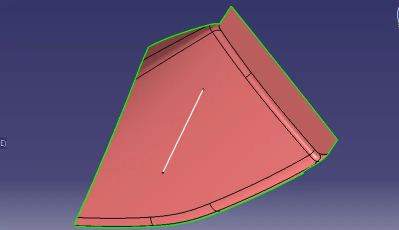
Draft analysis of class A surface
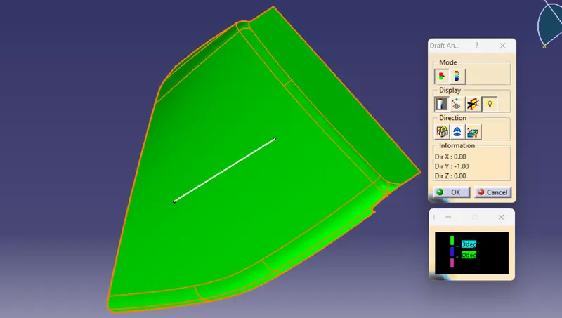
Class B Surface (Offset value 2.5mm)
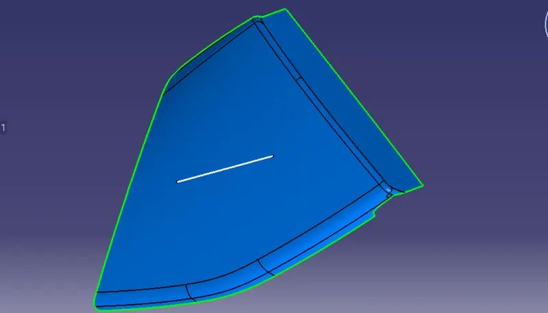
Class C Surface
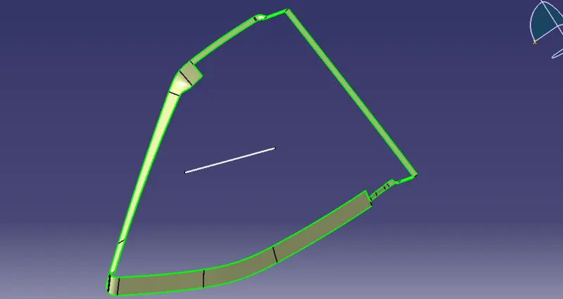
Close surface (Class A, B & C)
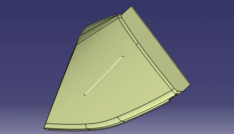
Solid body
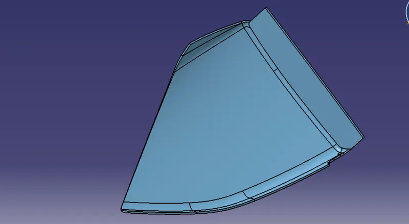
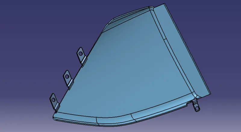
Flanges on the Map Pocket for attachment with the lower substrate
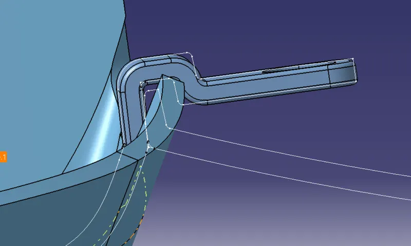
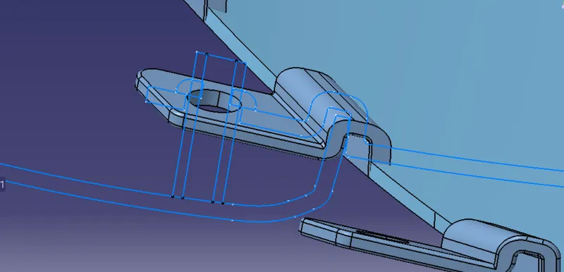
Whole Map Pocket body (minimum gap betweeb two flange is 50mm)
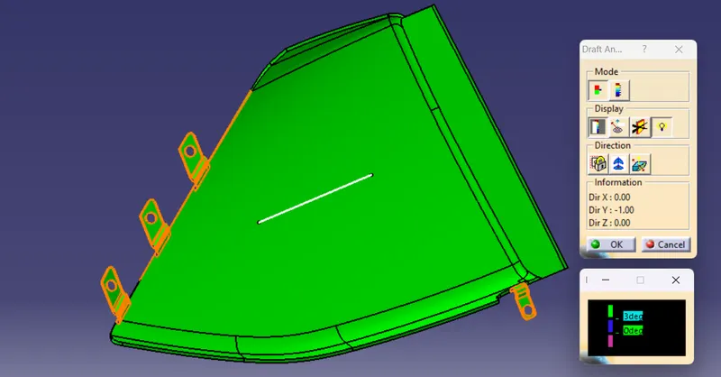
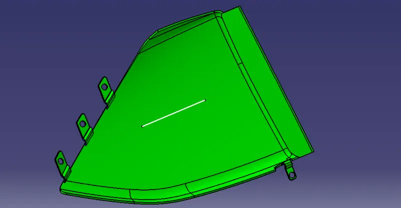
Draft analysis of final body
BOTTLE HOLDER:
Procedure
- Import class A surface
- Check boundry abnormality
- Create tooling axis
- Draft analysis of class A
- Create class B surface
- Create class C surface
- Joined Class A,B & C surface and make close surface
- Make it solid body
- Add flanges with master section
- Analysis final body draft analysis
Class A Surface and tooling axis
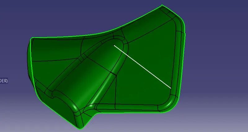
Tooling Direction
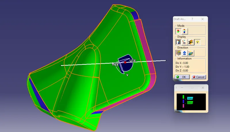
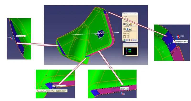
Class B Surface (Offset value 2.5mm)
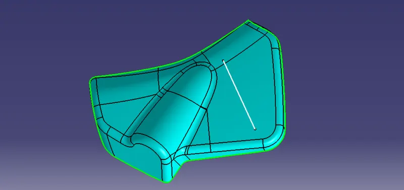
Class C Surface
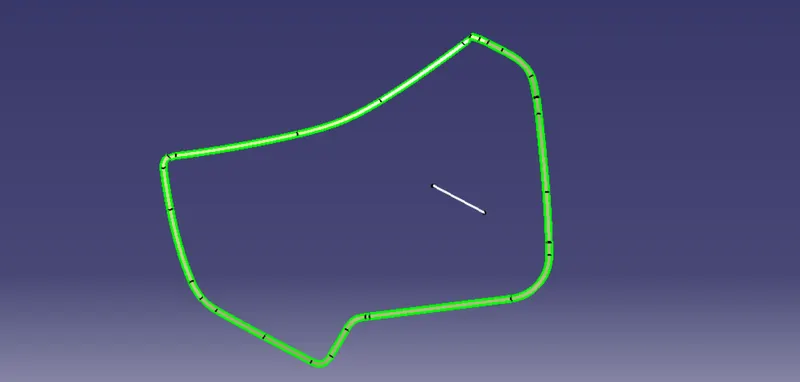
Close surface (Class A B & C)
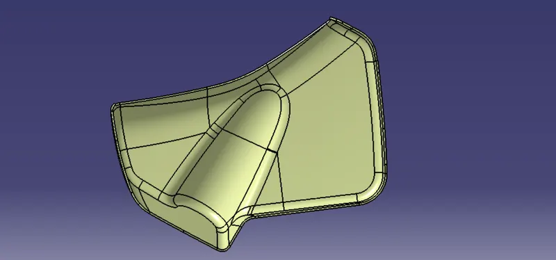
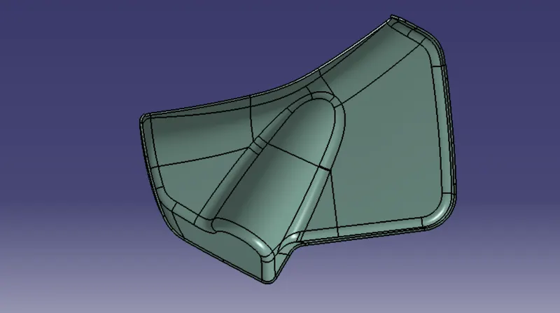
Solid body
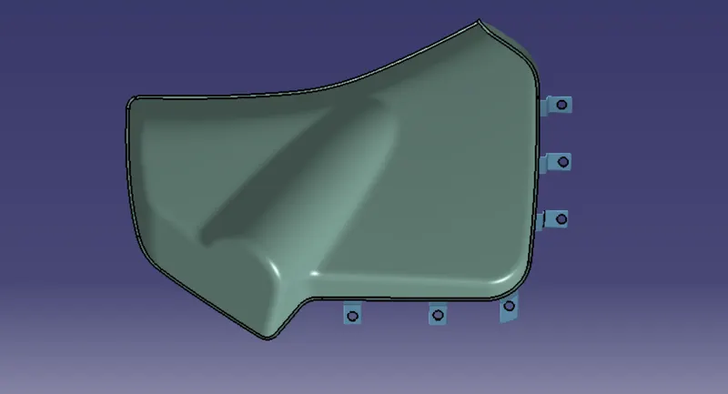
Flanges on the bottle holder for attachment with the lower substrate
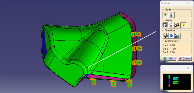
Draft analysis of final body along with tooling axis
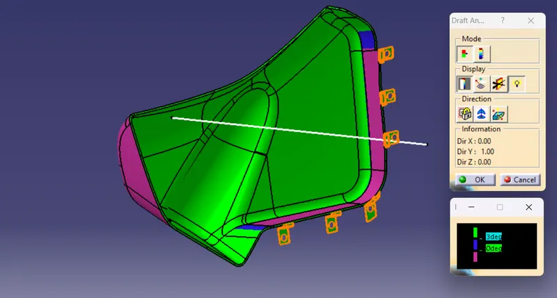
Whatever see in blue colour it also available in class A surface so it means solid body at 3 degree draft considerable
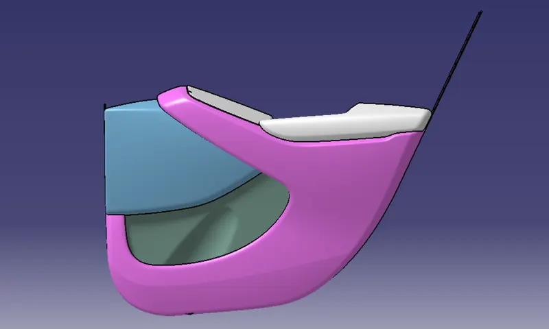
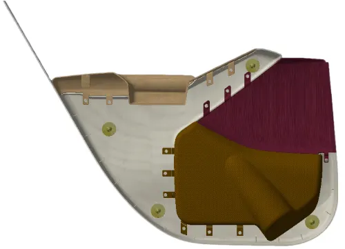
ASSEMBLY OF ENTIRE DOOR TRIM PANEL
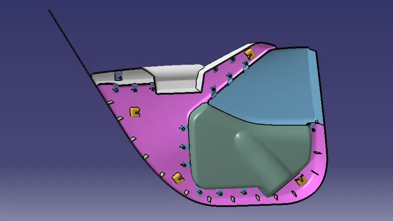
ARM REST Flange with heat sktakes
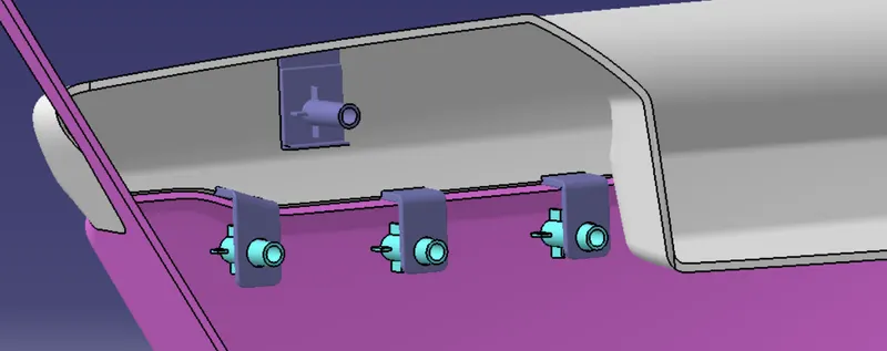
Arm Rest and Map Pocket flanges with heat stakes & locators
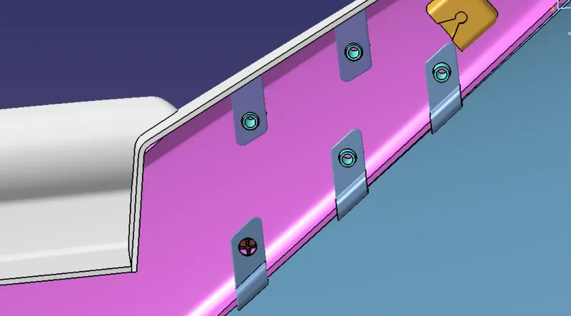
Bottle Holder flanges with heat stakes at lower substrate
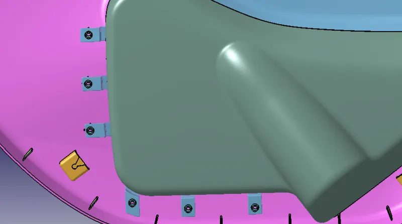
Map pocket base flange with locators
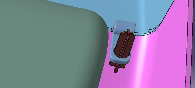
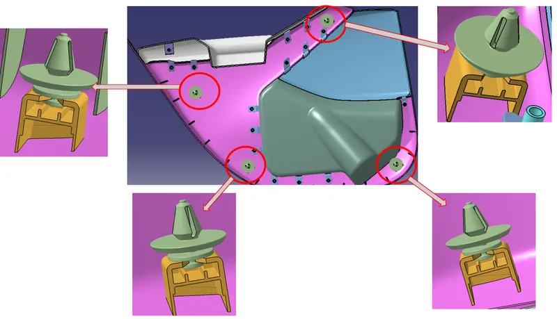
Assembly of Push Pin with Dog House at lower substrate
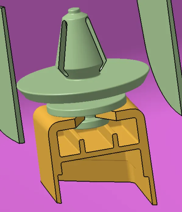
All 4 push pin attached with dog house at lower substrate as you can see in below figure
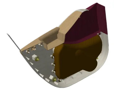
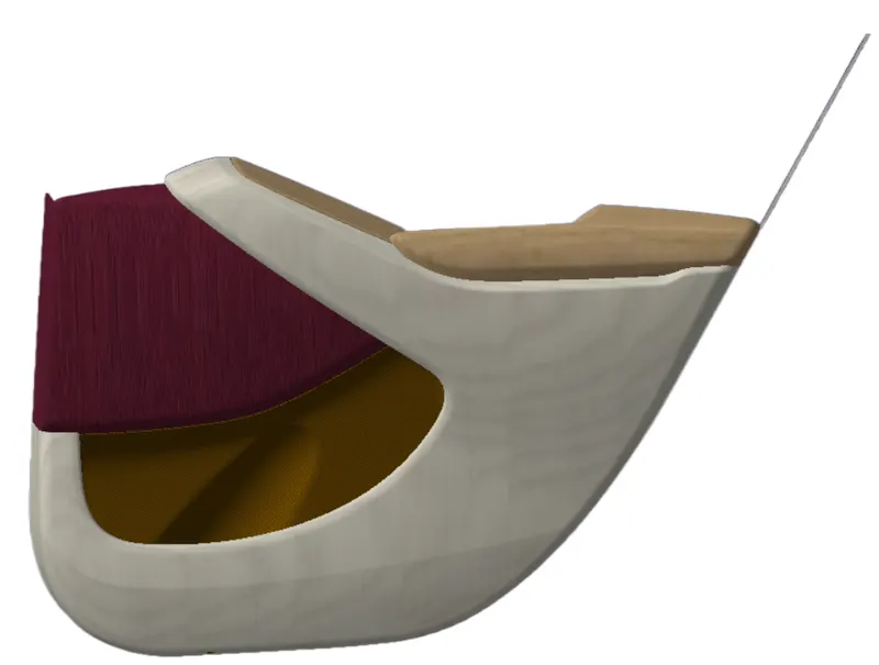
Apply material to all the parts
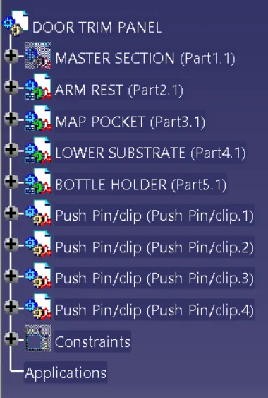
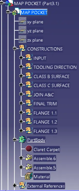
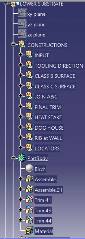
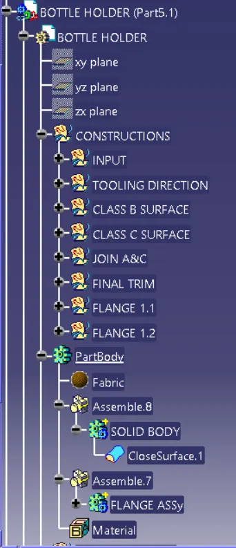
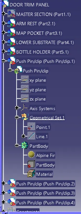
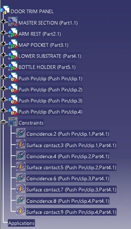
TREE STRUCTURE
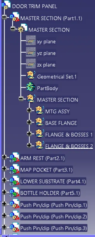
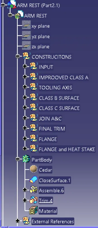
CONCLUSION
The Door Trim Panel is successfully designed from the given inputs Class A Surface and following industry standard design guidelines.