Week 12- Final project
REPORT ON FINAL PROJECT.
AIM: To create the solid part and the B side features from the given class A and master section inputs.
PROCEDURE: The procedure are as follows:
first we will recieve the class A of all the four main parts of the door trim panel as a single product single part file.
from that we have to make separate part files for each of the component. The four inputs which we recieved are as follows:
1.Arm rest
2.Lower substrate
3.Map pocket
4.Bottle holder
so here we have to make part files for each of this component.
Adding part files to the producft file:
first we have to add separate part file for each input and then we need to change the geometrical sets of them properly and then at last our output should be like one product file includindg four part file .
after getting the proper part file and product file we have save it using save management option and then we need to click on propogate directory option to save everything in a single folder single product file.
after getting the proper product and part file we have make the solid bodies as per the given master section.
MAKING SOLID BODY OF THE ARM REST AS PER MASTER SECTION.
first we will be having the class A as an input from that we have to make class B and class C and then the B side features as per the given master section.
the class A input will be as follows:
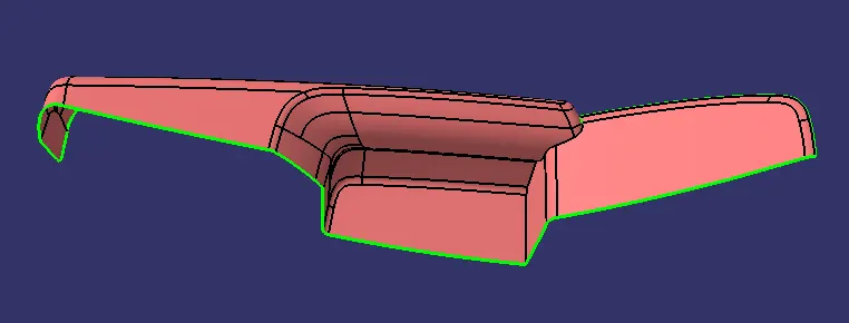
from this input we have to create the class B and then the classs C surface , but before that we have to check the quality of the class A whether it is having any boundaries in between or not.
Yes the class A which we recieved is having a boundary in between it so we have to improve our class A first and then we have to create class B.
the defected class A is as follows:
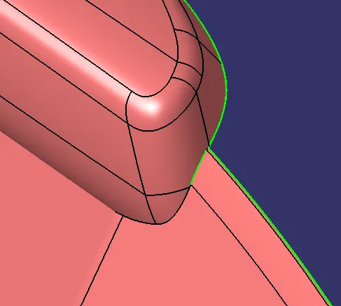
to make this proper we have to the surface and then we have to extapolate it and then we have to trim it and then the our improved class A will be as follows:
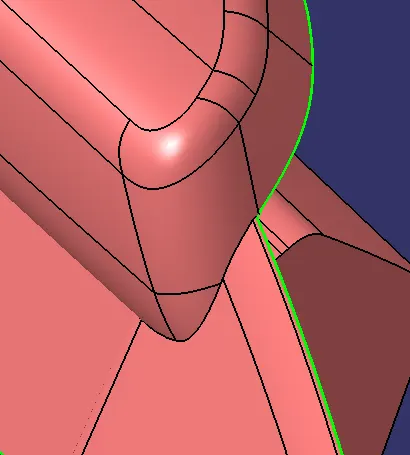
after getting the improved class A we have to create the tooling axis for it the most possible way of tooling direciton for any components is z direction and our component is also in possible to tool in z direction so we will create our tooling axis in z direction.
CREATION OF TOOLING AXIS:
to create the tooling axis it is very simple first we will take a extract of the required surface and then we will take a point on it and then we will take a line using point and direction method and we will use the point which we created and the direction as z direction. Whether we can do like this or else we can extract the the boundaries and then we can create the bisecting line and name it as a tooling axis. To make it properly visible we will increase the thickkness of the line and then we will give a colour to it and our output will be as follows:
after creating the tooling axis we have to do the draft analysis for the class A
DRAFT ANALYSIS FOR CLASS A:
first we have to place the compass in the tooling axis and then we have to measure the drafting angles for our component by using draft analysis command and our output willl be as follows:
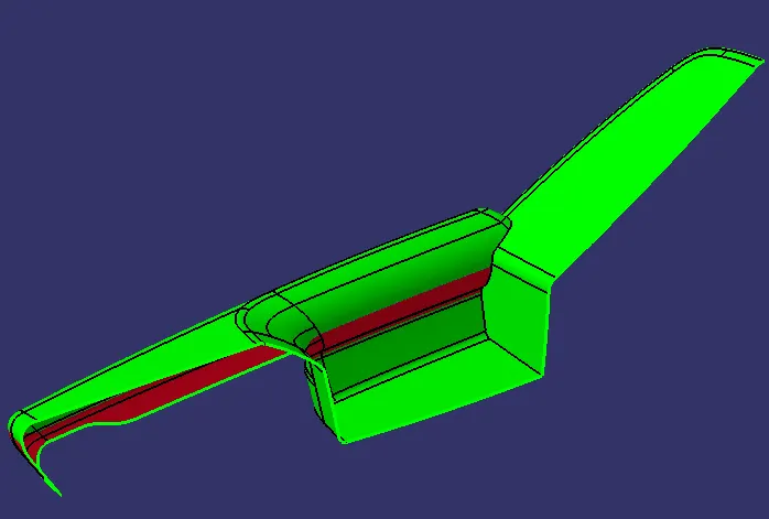
here we have got output in two different colours one is in green colour and the other one in red colour the green colour means our the draft is more than 3 degreee and the red colour says that the draft is less than 0 degree.
after doing the draft analysis we have to create the B surface for it. For creating the B surface we have to know the thickkness of the component .The thickkness of the component from the master section is 2.5mm so we will simply offset the class A to 2.5mm and then we will get the output as follows:
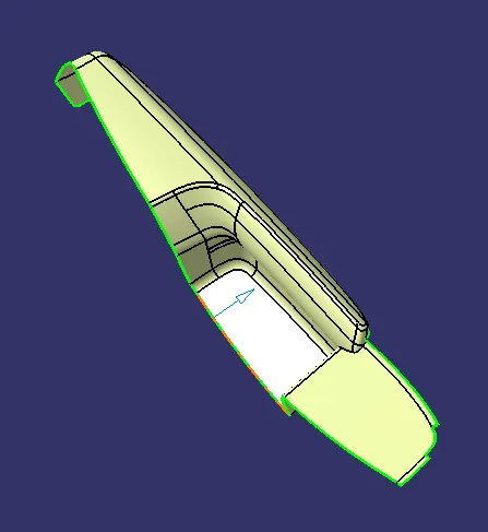
after offsetting it we will be having two defects in it the defects are as follows:
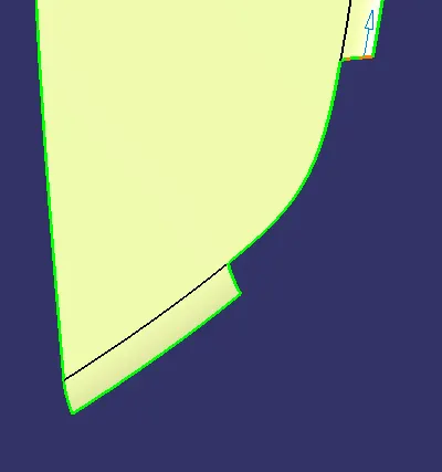
to make this proper we can do the multi section on it and then we can join them both and we will recieve the output as follows:
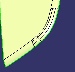
after clearing this patch we have to clear the other patch also the other patch is as follows: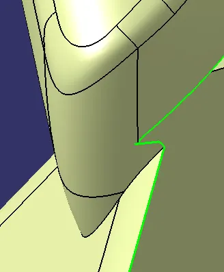
to clear this patch first we will extract the required patch from the class A and then we will untrim it and then we will offset it to the required distance and then our output will be as follows:
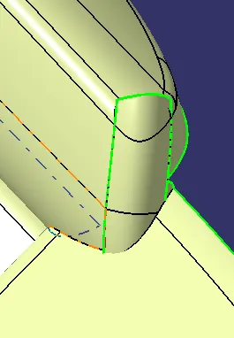
after getting the output as above we have to split that component to the required size and then we will use the join command to remove the patch and we will join our splitted surface and our output will be as follows:
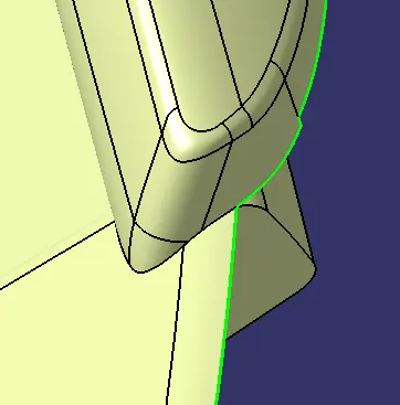
but the output which we got is extapolated little bit but that is not a issue why because it is going to be trim with the join of class A and class C.
so after gettting the proper B surface as above we have to create the class C surface.
for creating the class C for this component we have to create the boundary and then sweep it but for this component we can sweep it in two different methods one is sweep with draft direction which is going to be cleared in cavity part and the other is with reference surface which is going to be cleared by core part.
sweep with draft direction:
for this component whatever the faces which are perpendicular to tooling axis can be cleared by draft direction and the faces which are parallel can be cleared by reference suface and the gap between the two sweep can be cleared by multi section and our out put will be as follows:
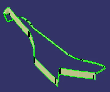
after getting the output as above image we have to join the it with the class A and then we have to trim the join of class A and C with the class B and our output will be as follows:
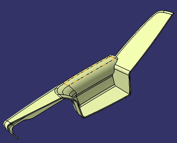
after getting the output as above we have make sure that our body is closed or not to make sure that we have to take a boundary if the boundary is not coming then our output is correct.
after getting the closed body we have to make it as a soloid body so we go back to part design and then we have to use close body command to close the surface and then our output will be as follows:
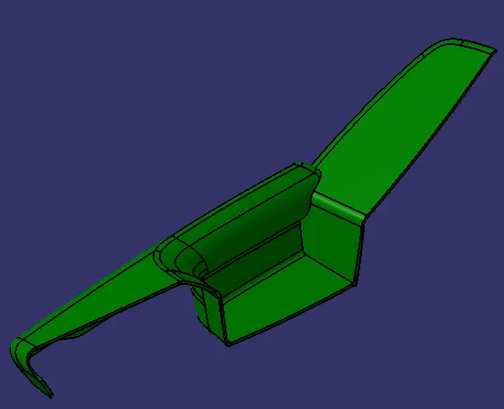
after getting the solid body we have too make draft analysis for the solid body also and our output will be as follows: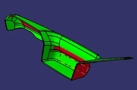
CREATING B AND C SURFACE FOR LOWER SUBSTRATE:
first we will recieve the class A of lower substrate as an input from that input we have to create B surface and C surface the class A input is as follows:
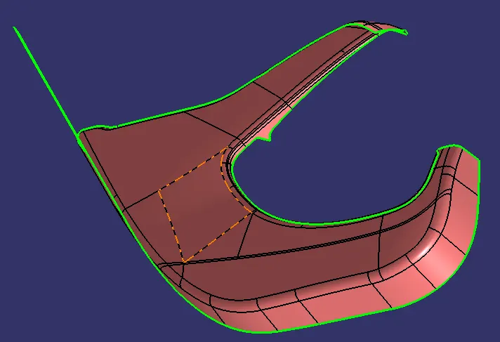
for this component first we have to create the tooling axis for creating tooling axis for this component the possible way is Y direction so we extract one surface of it and then we will create a point on it and then we will createa line using point and direction method using the point which we created and the direction of the line should be Y direction and our output will be as follows:
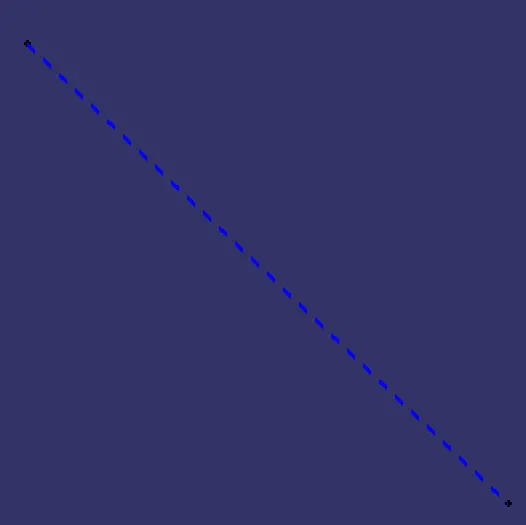
after creating the tooling axis we have to do the draft analysis fo the class A
DRAFT ANALYSIS FOR CLASS A:
first we have to place the compass in the tooling axis and then we have to measure the drafting angles for our component by using draft analysis command and our output willl be as follows:
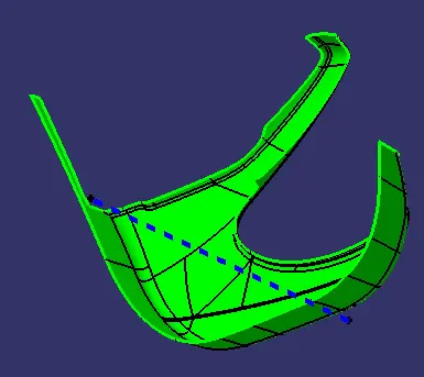
after creating the tooling axis we will create the B surface for it For B surface as per the master section the thickness of the component is 2.5 MM So we will directly offset the Class A to the 2.5 mm and our output will be as follows: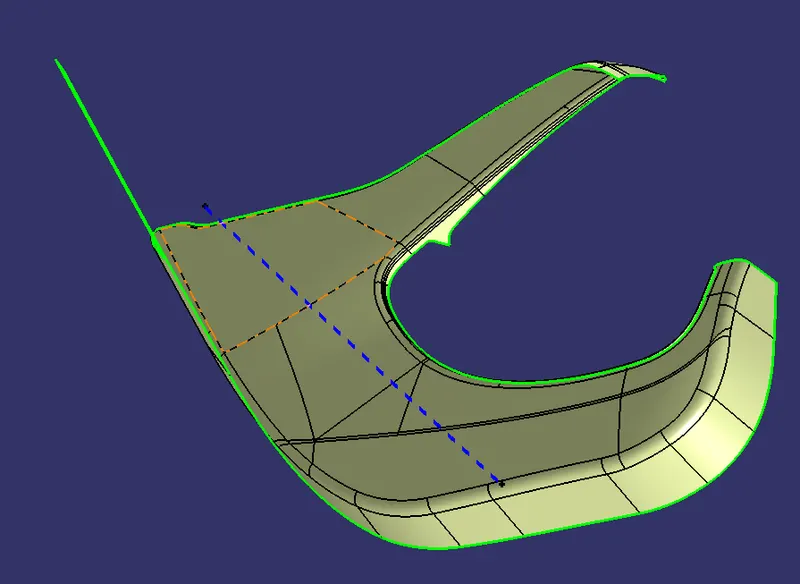
after getting the offset we will name that offset as B surface and then we have to create C surface for it.
for this component all the faces are parallel to the tooling axis so we will do the sweep with reference surface and our output will be as follows:
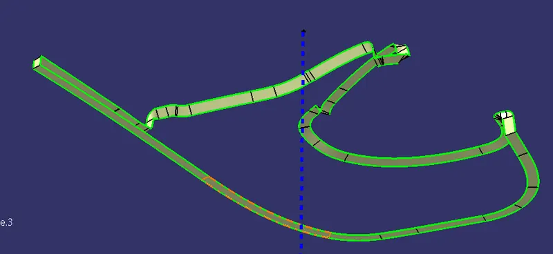
after getting the output as above we have to join it with the class A and then we have to trim it with the classs B and our output will be as follows:
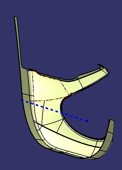
after getting the closed body as above image we have to ,make it as a solid body to make it as a solid body we will go back to part design and then we will use close surface command to close the surface and then we will recieve the output as follows:
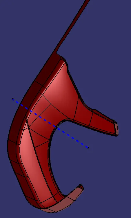
after getting the solid body we have to make the drfat analysis and the output will be as follows:
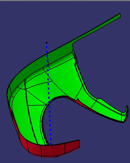
after getting the lower substrate solid part we have to create the map pocket solid part.
MAP POCKET CREATION.
as usual we will be having the class A as an input from that input we have to make solid body for making solid body first we will create the tooling axis.
CREATING TOOLING AXIS:
for tooling axis first we have to check the proper tooling direction. for this component the tooling direction is Y direction. first we will extract the one of the surface from class A and we have to create a point and then we will create a line using point and direction method using the point which we created and the direction as Y direction and we will name that line as tooling axis and our output will be as follows:
after creating the tooling axis we have to check the drafting analysis for the class A.
DRAFTING ANALYSIS FOR CLASS A:
first we have to place the compass on the tooling axis and then we have to click the drafting analysis command and then we have to click on the class A and then we have to check the angles of our component and our boutput will be as follows:
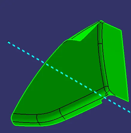
here we have got output in only one colour and that is green colour which says that the draft for our component is more than 3 degrees.
after checking the drafting analysis we have to create the B surface.
CREATING B SURFACE:
for creating B surface first we have to know the thickkness of the component the master section will help us to measure the thickkness of our component by measuring the master section we came to know that the thickkness is 2.5mm so we will offset the class A to 2.5mm thickkness and we will recieve the output as follows:
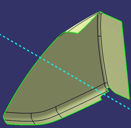
after offsetting it here we have got a issue that one of the surface is missing so we will create a spline and then we will do the multisection and we will join it to the main offset and we will recieve the out put as follows:
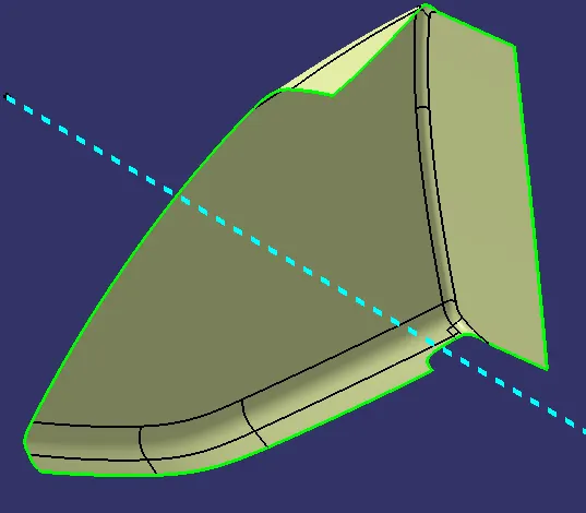
and after getting the output as above image we have to create the C surface for the class A.
CREATING C SURFACE
for creating c surface we will create a boundary and then we will sweeep it with refrence surface and draft direction method and the places where we cant create them we will use the multi section and at last we will join all and we will recieve the output as follows:
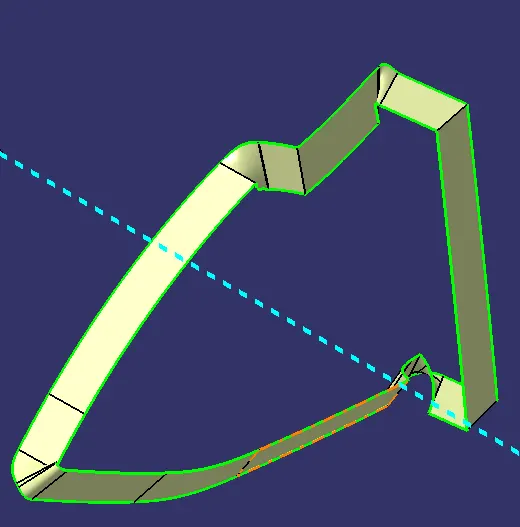
after getting the output as above image we will join it with the class A and then we will trim it with the class B and we will recieve the output as follows:
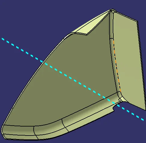
after getting the closed surface we have to make it as as solid body for making it as a solid body we will go back to part design and we will use close surfaace command to get the solid body and our output will be as follows:
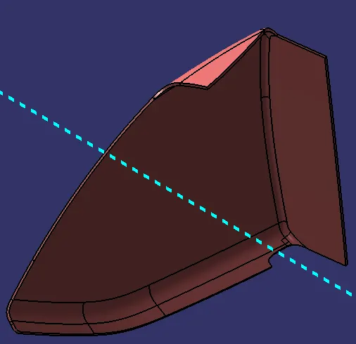
after getting the solid body we have to do the draft analysis for the solid body we will follow the same procedure which we followed for the class A draft analysis and our output will be as follows:
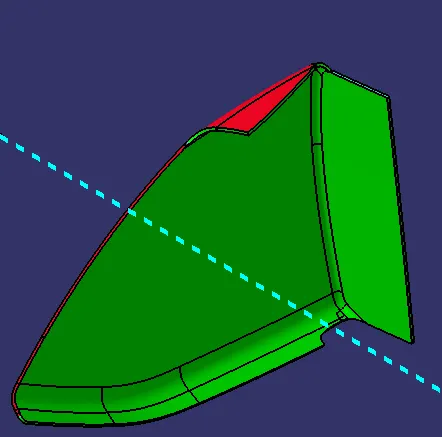
once the draft analysis is done for the solid body and it is correct means our component is ready for manufacture.
BOTTLE HOLDER CREATION:
as usual we will recieve the class A as an input from tht class A we have to create the classB and the class C and we have to make it as a solid body the class A input will be as following image:
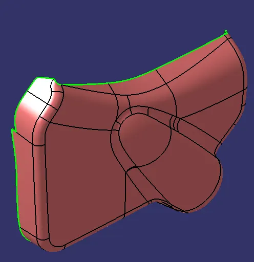
from the classA we have to cfreate the class B and the class C surface but before creating the class B we have to create the proper tooling axis for the component.
CREATING TOOLING AXIS:
for creating the tooling axis first we have to know the proper tooling direction for our component. The proper tooloing direction for our component is Y direction so we simply extract one of the surface from the class A and we will create a point on it and then we will create a line with point and direction method using the point which we created and the direction as Y direction and we will name the line as tooling axis and our output will be as follows:
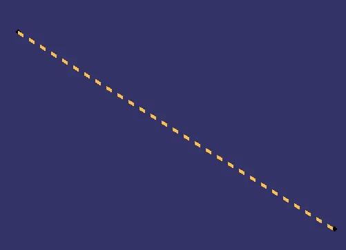
after creating the tooling axis we will do the draft analysis for the given class A to check the drafting angles and we will place the compass on the tooling axis and do the draft analysis and our output will be as follows:
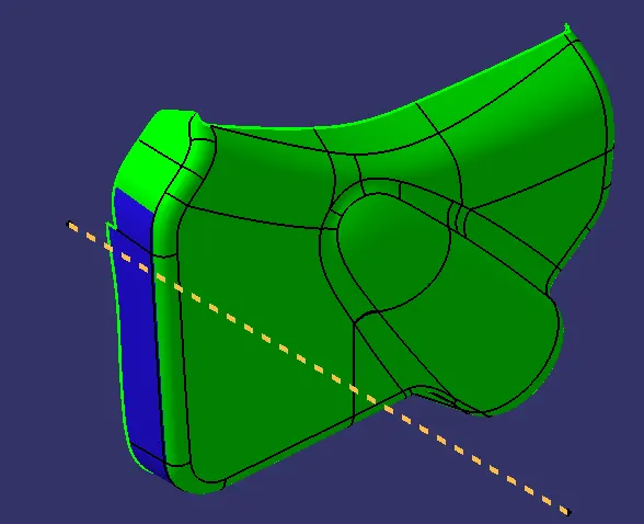
but here the output which we frecieved is having two different colours one is blue and another is greeen which means the green says that draft is more than 3 degree and the blue says that the draft is less than 3 degree.
after doing the draft analysis we have to create the B surafce.
for creating the B surface we will simply offset the class A to the required distance as per the master section and then we will name that offset as B surface and our output will be as follows:
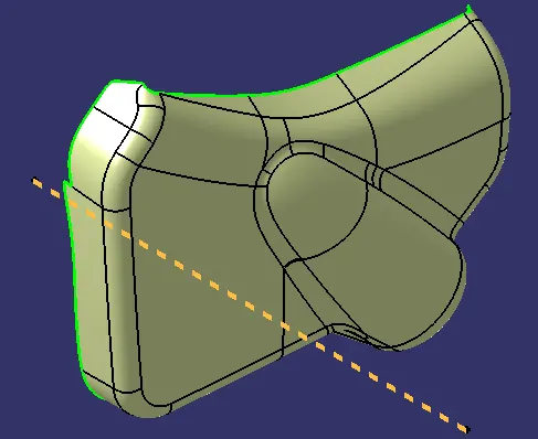
here in our B surface there are no boundaries in between the component so our B surface is good to go
after getting the B surface we have to create the C surface. for creating the C surface for this component we will use the swep command with reference surface and we will recieve the output as follows:
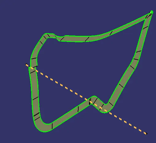
after getting the c surface we will join it with the class A and then we will trim it with the class B and we will recieve the output as follows:
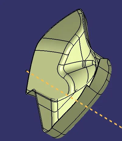
after getting the closed surface we have to make it as a solod body for making it as a solid body we will go back to part design and use close surface command to get the solid body and our out put will be as follows:
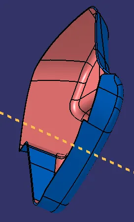
fater getting the solid body we will do the draft analysis for the solid body we will follow the same procedure which we followed in doing the draft analysis for class A and we will recieve the output as follows:
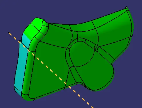
after doing the drfat analysis our botlle is ready.
after getting all the solid part we have to go bo back to assembly workbench and unhide all parts and then our output will be as follows:
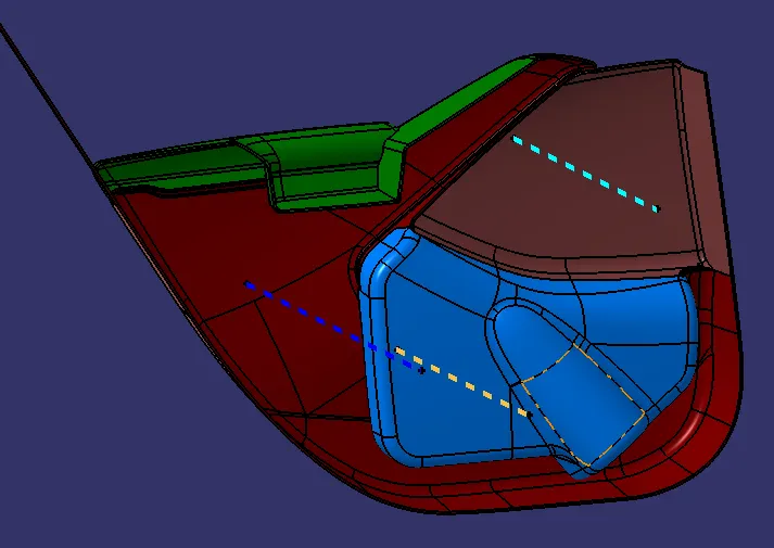
after getting all the solid parts we have to do the B side featuresacoording to the master section.
the master section which we recieved is having a heatstake and the flange.
CREATION OF HEAT STAKE AS PER MASTER SECTION.
for creating the heat stake first we have to take a between point on thwe master section and we have to isolate it and then we have to measure the dia of the heat stake and then we have to make a sketch and pad it and then we have to do the drfat for heat stake the minimum draft should be 0.5 degree.
after getting the heat stake we have to create ribs for the heat stake the length of the rib should be upto the flange height so that the falnge will rest on the rib and we have to draft the rib also and we have to give chamfer to the edges of rib and fillets and later we have do the union trim with the heatstake and we will recireve the output as follows:
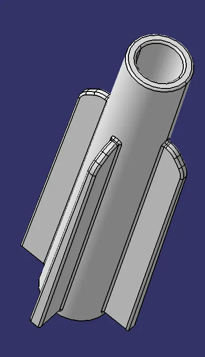
after getting the heat stake we want it to be in more places because one heat stake is not enough so we will simply extact the b surface and multi extract the the edge and we will use parallel curve and measure the distance between the first heat stake and the edge and we will give the same distance for parallel curve and we will recieve the output as follows:
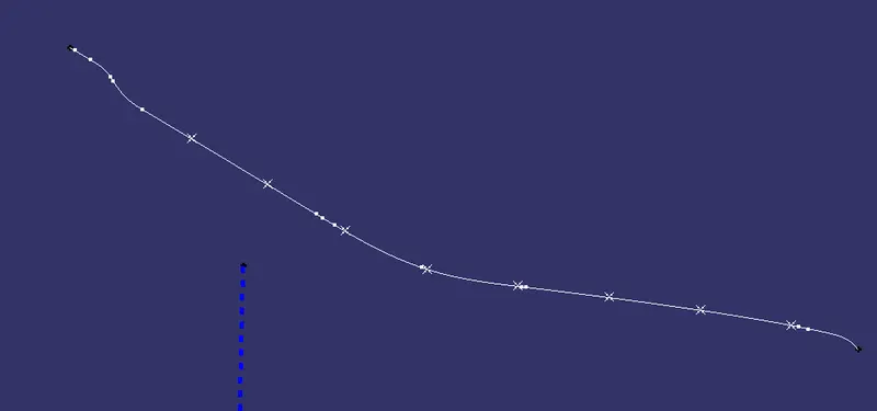
after getting the parallel curve we will have repetition points on it and the spacing betweeen each point should be 50mm so that we can later translate the heat stake to that point.
after getting the point we will copy the heat stake body and paste special as result with link to the N number of times as much as we want and we weill transllate it where ever we want .
we will have heat stakes all over the lower substrate because the lower substrate is the part which will connect all the other parts so we will have heat stakes all over the lower substrate and our out put will be as follows:
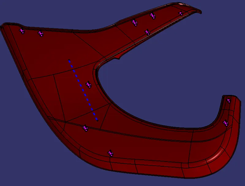
after getting the heat stake where ever we want we will have one locator between each heat stake so that the component will stay strong
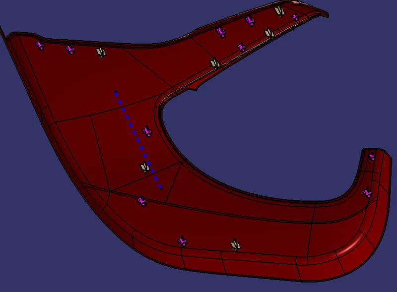
for creating locator we will use same plane and point which we created for heat stake and have the locator sketch and then we will create the locator to the the height of certain mm the height should be more than the heat stake and we have to draft the locators also for 0.5 degree and the chamfer and the fillets has to be given and then our output will be as follows
after getting the locator we will create repetition points between heat stakes and translate it and the output will be as follows:
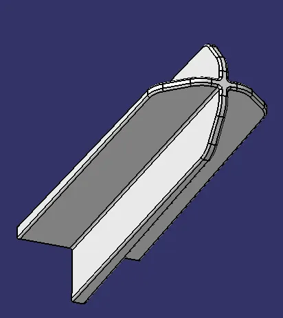
after getting tbhe heat stake and locator the rest three parts has to flange for each heat stake and locator for creating the flange the master section is given for the map pocket and the arm rest but for bottle holder the master section is not given so for bottle holder we will create it by our own.
FLANGE CREATION.
first we will have a palne and a point to create the falnge and we will take extract of the c surface and we will have a intersection between the plane and the extract and then we will draw the flange acoording to the master section and sweep it with profile and guide curve and then we will thickken it and then we will do the solid split to the required distance and then we will give draft and fillets and then finally our output will be as follows:
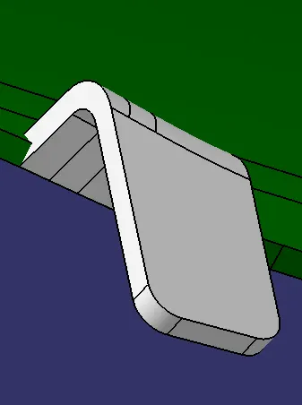
after getting the flange we have to give the clearence for heat stake to give clearence we will do the sketch for 8.5 mm circle because the heat stake dia is 7.5mm and we will extrude the sketch and our output will be as follows:
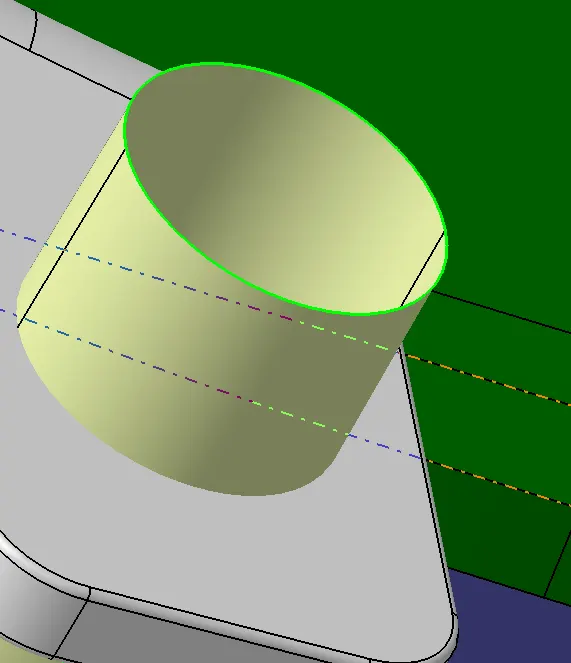
after getting the output as above we will do the solid split and the draft aand the fillets then our output will be as follows:
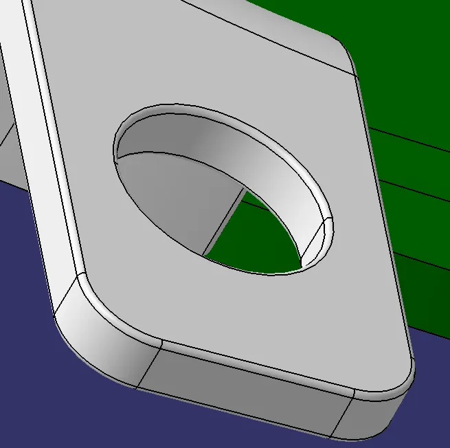
once if we get the output as above image then our falnge is redy like same procedure we will follow for creating all the flanges.
we will do the union trim of flanges with their respect part bodies and we will recieve the output as follows:
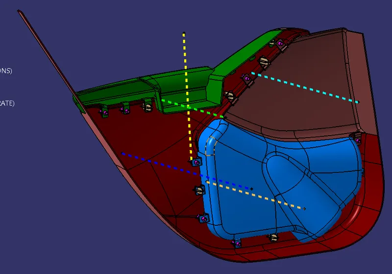
after getting all the heat stakes, flanges, and locators we are having one more input as push pin that push pin has to be placed on the top of the dog house so we need to create dog house and then we need to place the push pin on it.
CREATION OF DOG HOUSE.
as per the instructions we should have minimum 3 dog house so we will select three locations for it and then we will create a point on that locations and then we will create a plane with normal to curve and use the tooling axis as curve and we will have the dog house sketch.
The dog house sketch is not given in the master section so we will create it by our own and then we will do the essential things which we done for the dog house and then later we will union trim with the part body our output will be as follows:
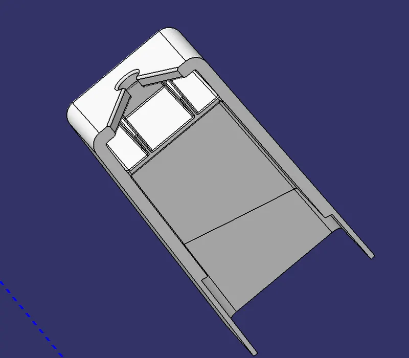
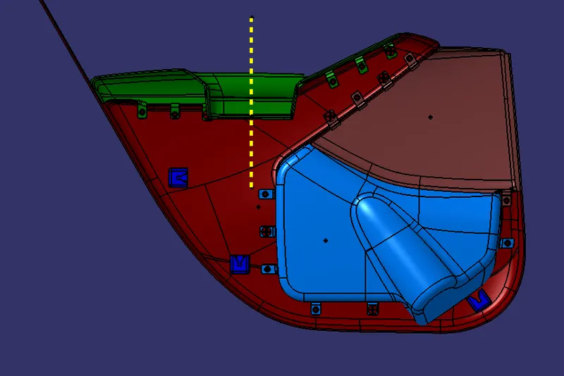
after getting the dog house we will union trim alll the B sude feature with respect to their part bodies and then at last our output will be as follows:
after getting all the things we have to assemble the push pin on the top of the dog house.
PUSH PIN ASSEMBLY.
for assembling the push pin first we have to go to assembly workbench and then we have to fix the main part bodies and then we have to coincide the push pin axis and dog house axis and then we have to offset the top face of dog house and bottom face of pushpin to the valuse of 0 mm and then we will recieve the output as follows:
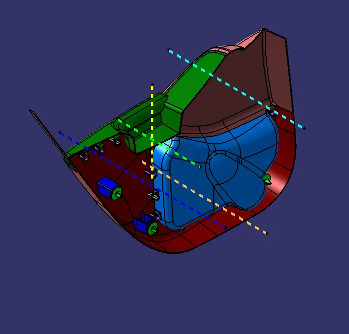
once if we get the output as above image then our project is done.