Week 12- Final project
AIM :- To create a CAD model for door trim panel's parts by considering the given inputs of class A surface along with master section by following the design rules followed in OEM and tier1 companies.
Objectives :-
- To create individual tooling axis for the parts and perform draft analysis on the class A surface
- To create the class B and class C surfaces from the given class A surface
- To form a solid geometry by combining all the surfaces
- To decide an attachment strategy for the part and create engineering features in reference from the master section provided
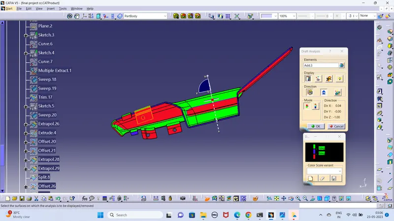
- To perform draft analysis on the solid part model with all engineering features
- To assemble all the components togehter to obtain the final trim
Given Data :-
- Class A Surface for Door Trim Panel -
As we know in automotive industry there are complex products that we have to design but this is not possible with simple sketches for that we need Class A Surface.
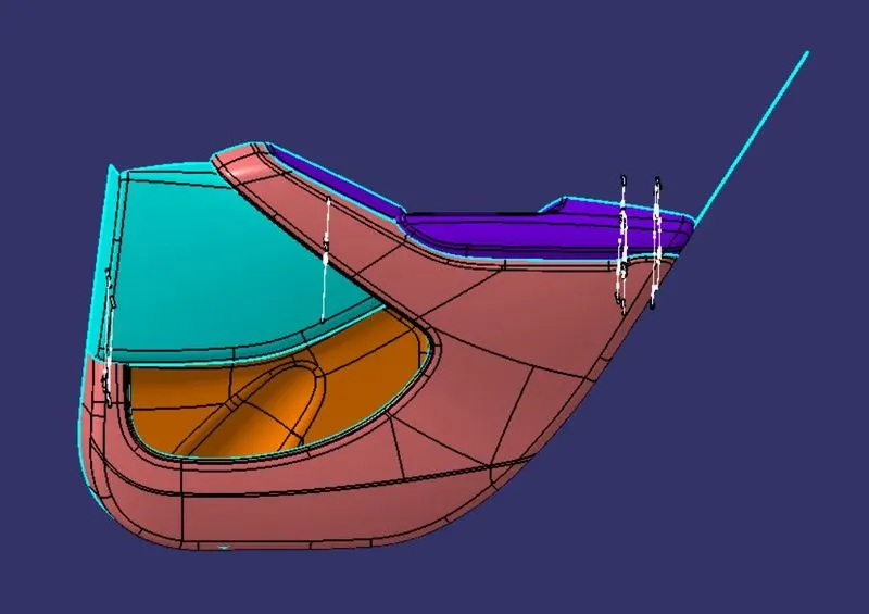
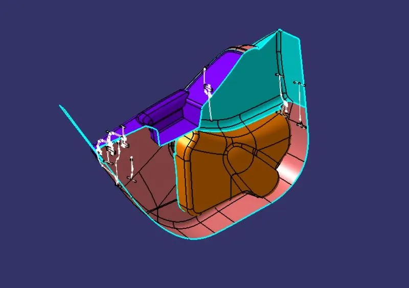
The A-surface or the styling surface is first checked for any gaps and other issues in its surfaces. This Surface acts as the input surface so any correction to be done should be with approval from the styling team or done by them. A- perfect surface is the one when a boundary is created, the lines are only on the edges of a component and its holes or cutouts as shown below.
Steps Follwed for Completion of Project :-
The door trim panel is created by follwing steps -
- To check given Class A surafces for any modification.
- To segregate given surafces into separate part body namely Lower Substrate , Arm Rest , Map Pocket , Bottle Holder.
- To work individually on each part.
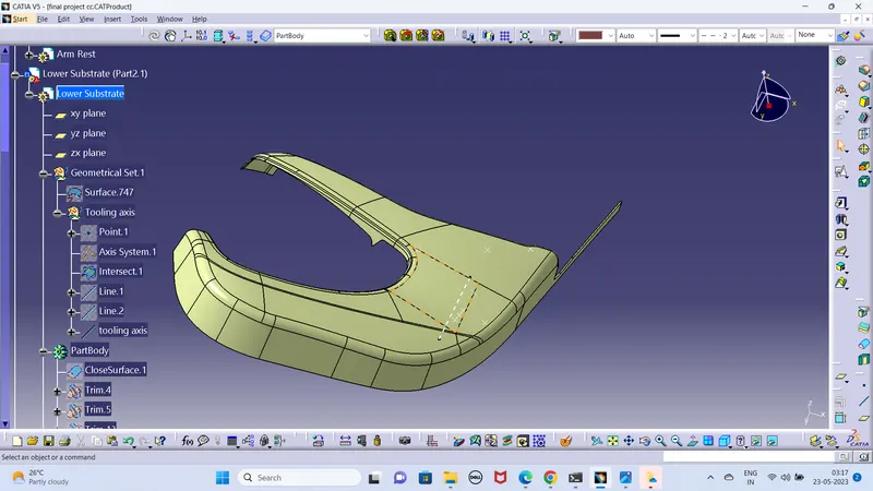
- To create tooling axis for part.
- Draft analysis on class A surafce.
- Creation of class B and Class C surafce.
- Craete closed body from Class A , B and Class C surface.
- Follwed same procedure to craete all parts .
- Then create attachement features for all parts.
- Then do Draft analysis on final parts and then constrain them for assembly.
- Class A Surface -
- Check Given Class A Surafce for improvement
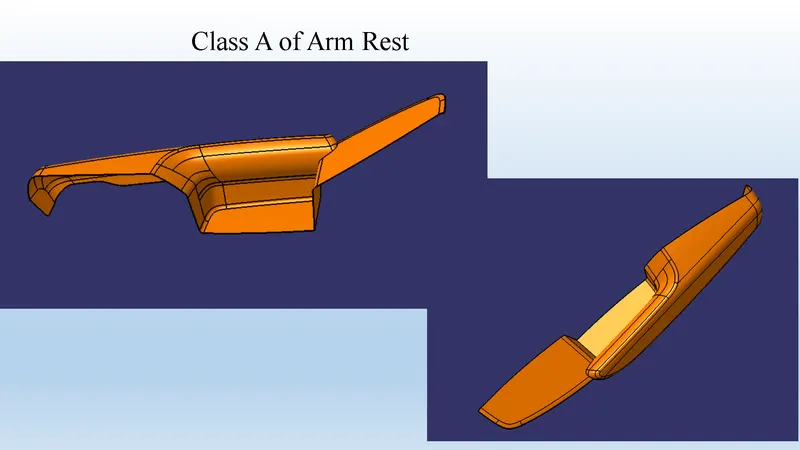
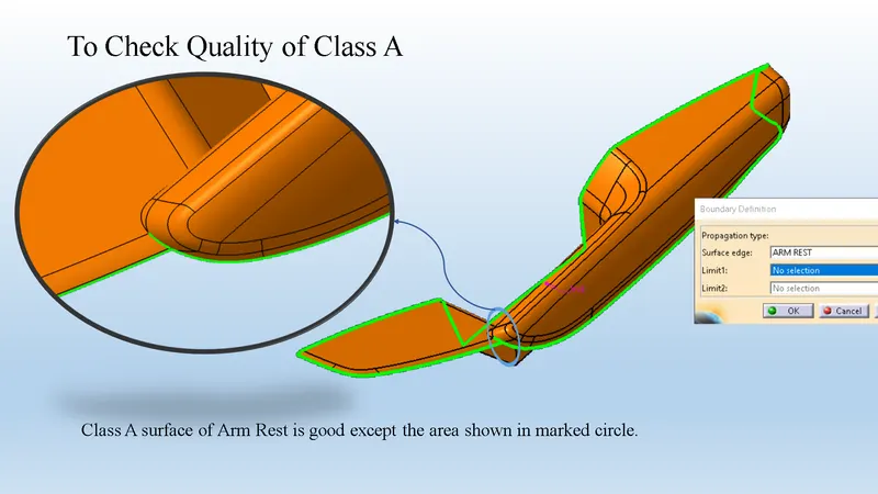
Class A surface not not first repair it.then creat B surface.
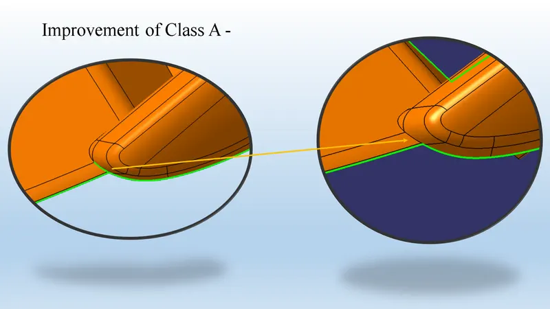
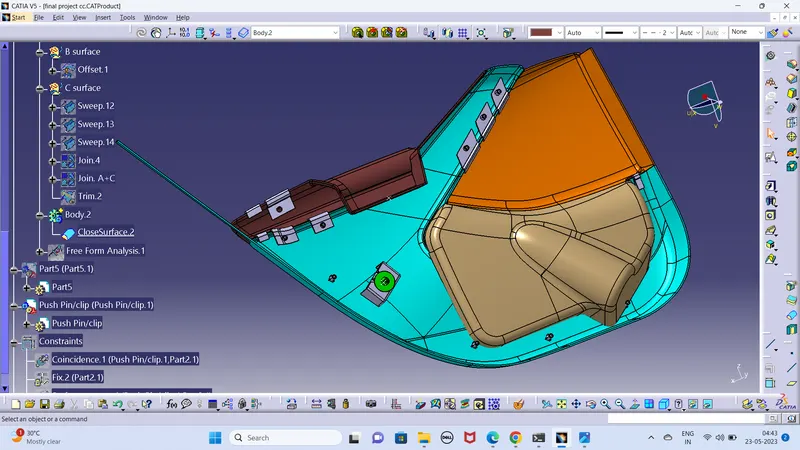
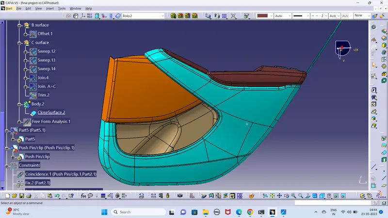
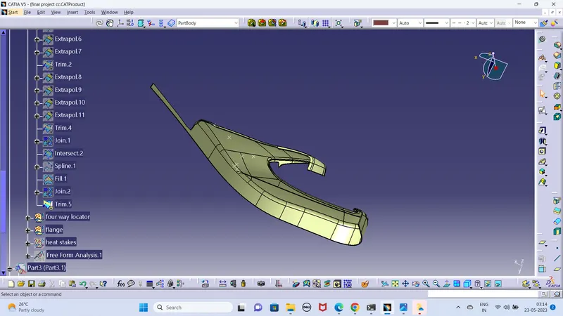
As shown in above image I have improved given class A surface in surafce workbench by using surafce operation such as extract, extrapolation , trim etc.
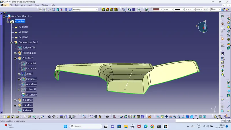
Corrected Class A surface
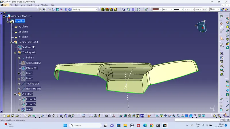
Tooling axis-
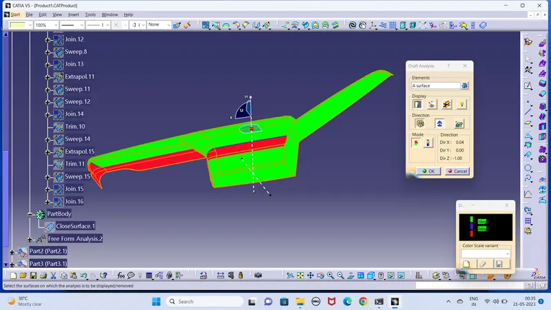
Draft Analysis-
B surface
Offset A surface 2.5
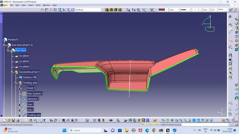
after offseting find some break surface first repair it
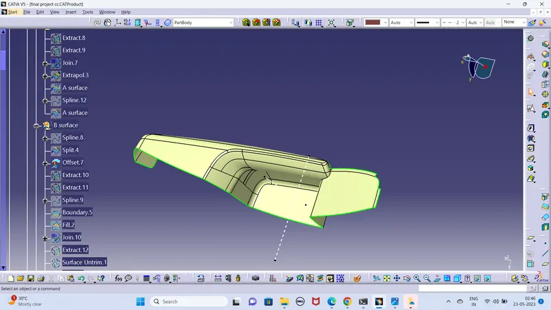
improved B surface
Class C surface
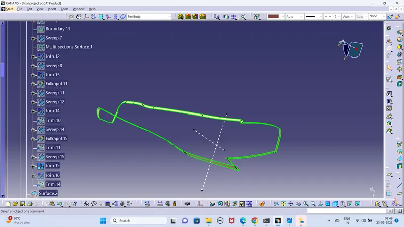
Complete C surface
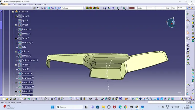
Closed surface
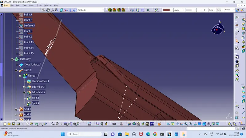
Flange Creation
with the help of master section
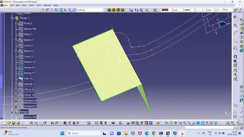
Flange Thickness2.5 mm
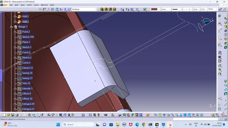
Final Arm Rest component
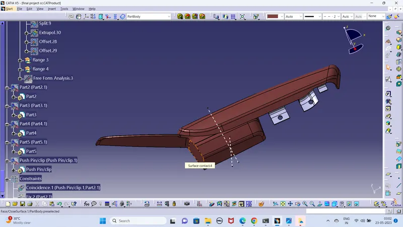
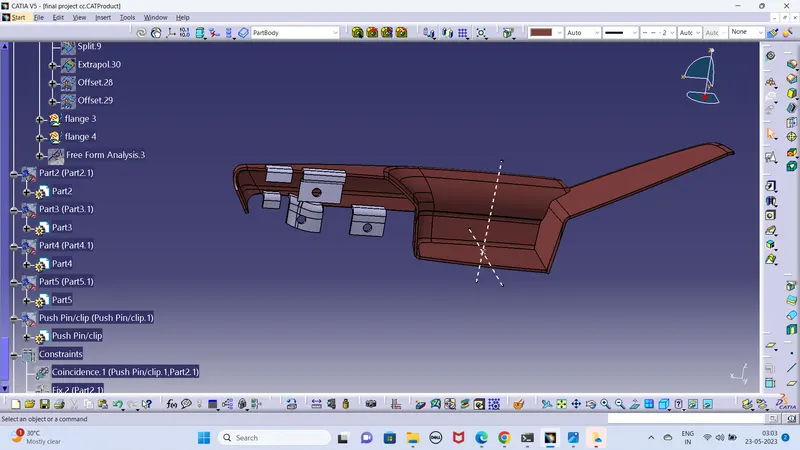
Final component Thickness is 2.5 mm
Draft analysis of Final part
LOWER SUBSTRATE
Class A surface
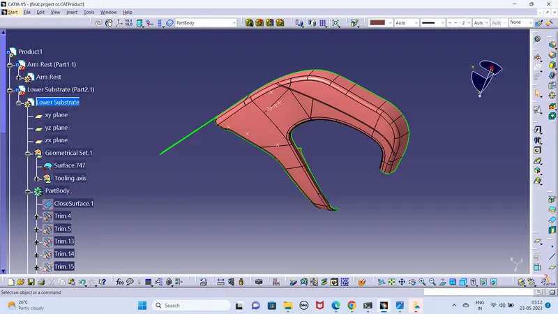
Tooling Axis
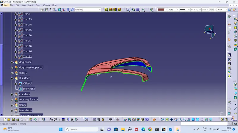
B surface
offset 2.5 mm
Class C surface
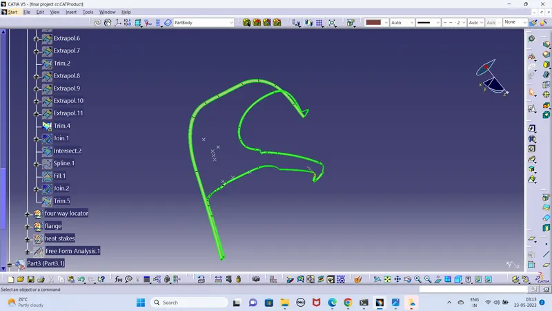
Final C surface
- Creation of Dog House.
General Guidlines for Dog House:
- "C" is where the doghouse contacts the backside of the surface.
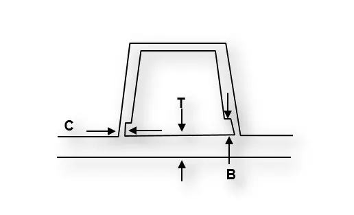
-
Doghouse wall thickness at the intersection of the part wall ( C ) should be 40% or less than the main wall stock ( T ).
-
The height of ( B ) should be between 3.0 – 6.0 mm.
- Minimum Doghouse Width (X) for doghouses is 12 mm.
- Minimum Draft (D) for doghouse is 1.5 degree* to die draw
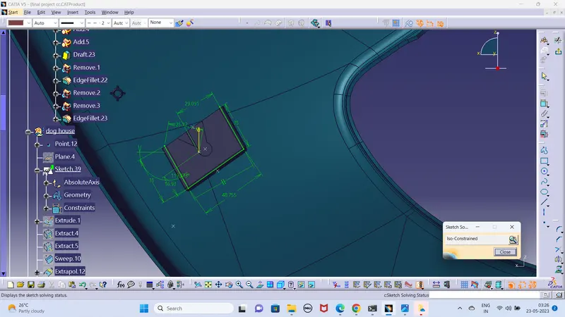
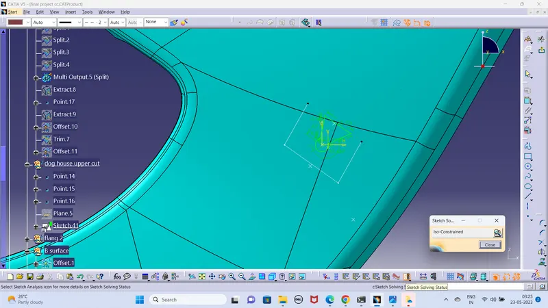
Extrude it and used thick surface methode to creat a Dog house
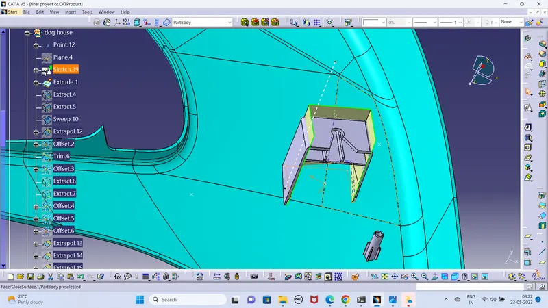
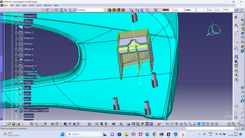
dog hose upper cut
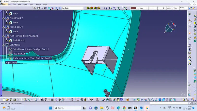
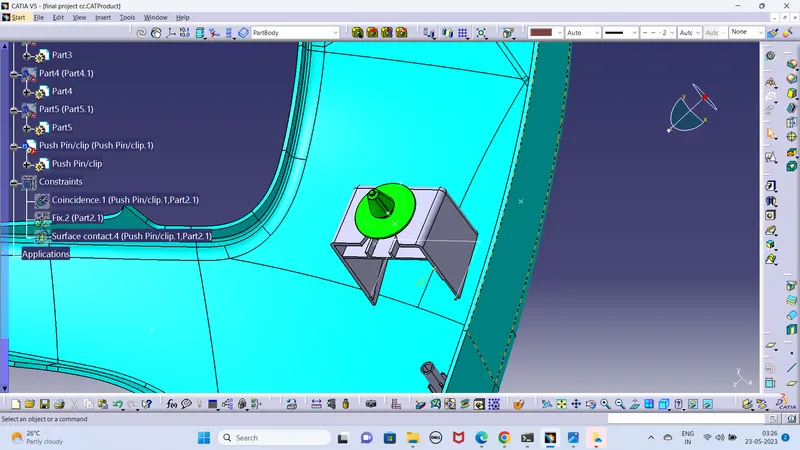
Push pin clip insert into dog house
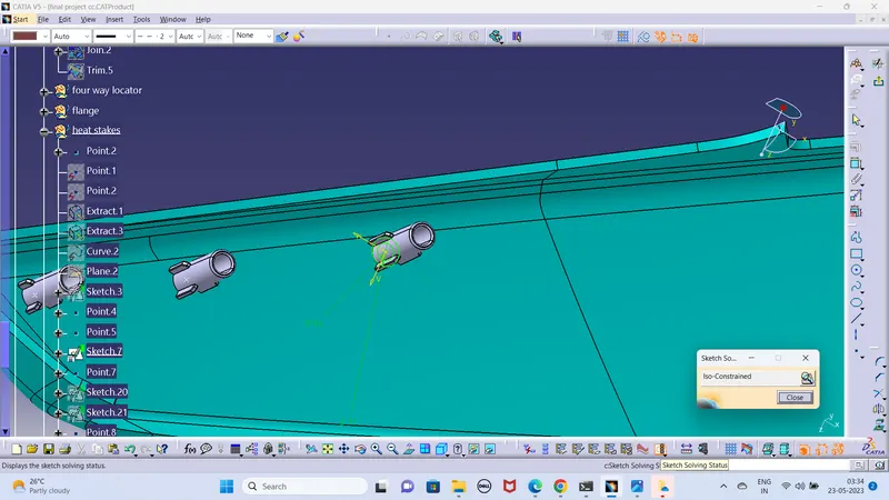
- Creation of Heat Stakes.
Thermal staking is an assembly method that uses the controlled melting and reforming of a plastic stud or boss to capture or lock another plastic or metal component of an assembly in place.
Guidelines for creating Heat stakes:
- Minimum 15 mmm gap between heat stakes.
- Maximun clearence with The counter clearence should be 0.5 mm.
- Maximum fillet radius be 0.25 mm..
- Draft : 0.5* per sides.
- Creation of locators.
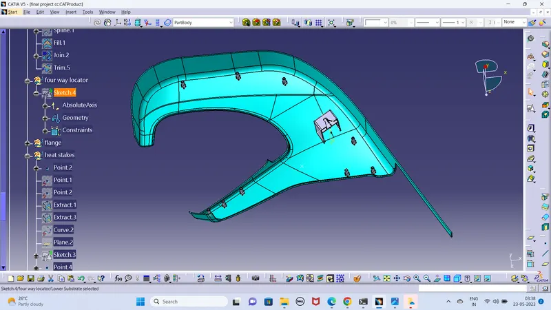
Locators are used to positioned the components in exact location and act as a guide for joining the two components.
Guidlines for Creating Locators:
- Draft : 0.5* per sides.
- Thickness - Tipically 40% wall thickness.
- Maximum fillet radius 0.25mm.
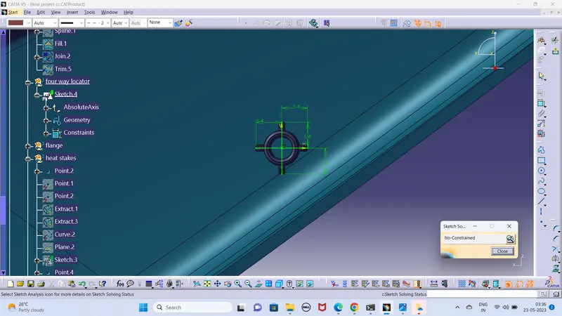
Final plastic component thickness is 2.5 mm
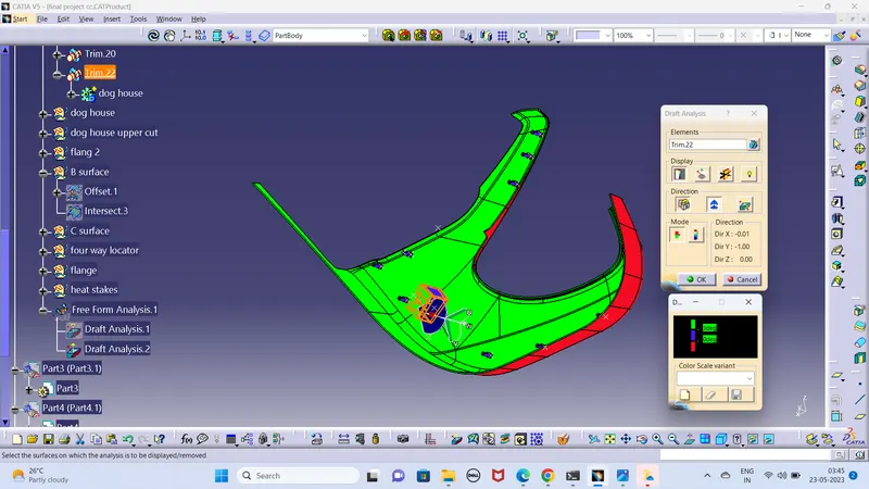
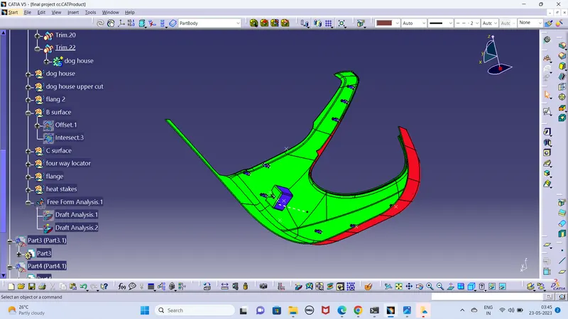
Draft analysis
Class A surface
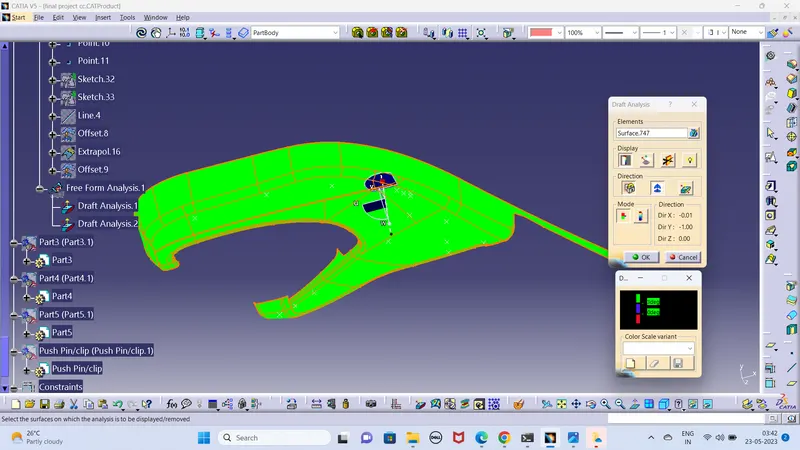
Final surface draft analysis
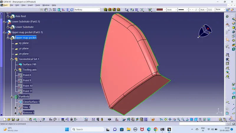
Upper Map Pocket
Class A surface
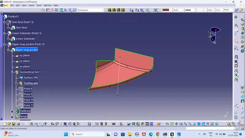
Tooling Axis
Offseting 2.5 For B surface
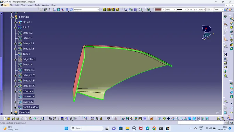
Some area are missing
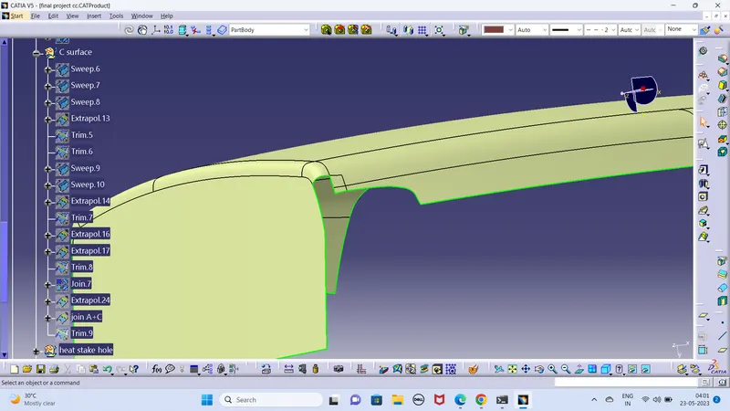
Repair the missing area
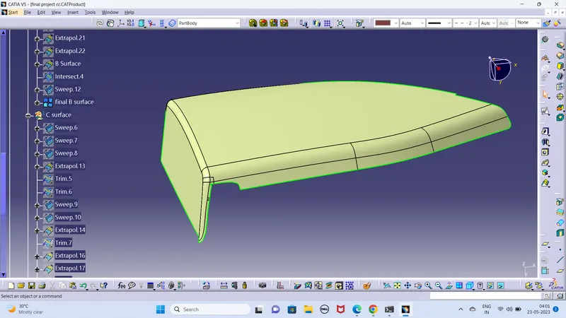
Class C Surface Creation
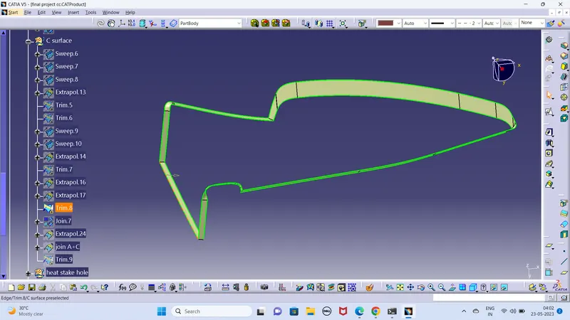
Fianl Surface
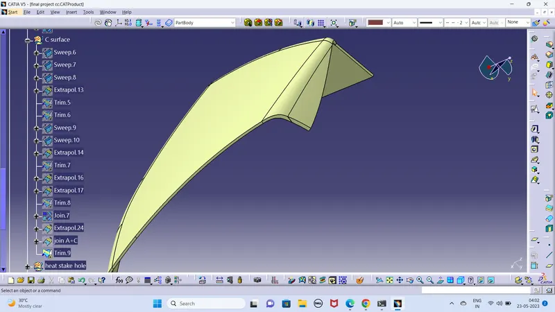
Flange creation
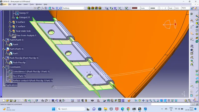
flang thiickness is 2.5mm
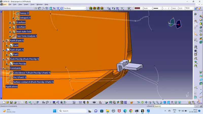
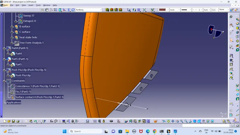
Final Surface hole hole thickness is 2.5 mm
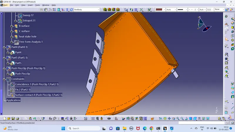
Draft analysis of A surface
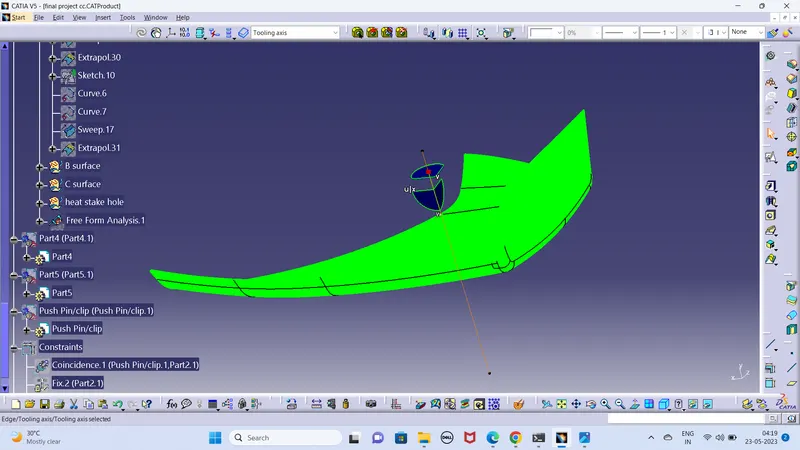
Draft analysis of Final surface
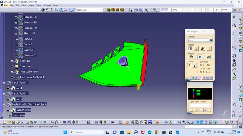
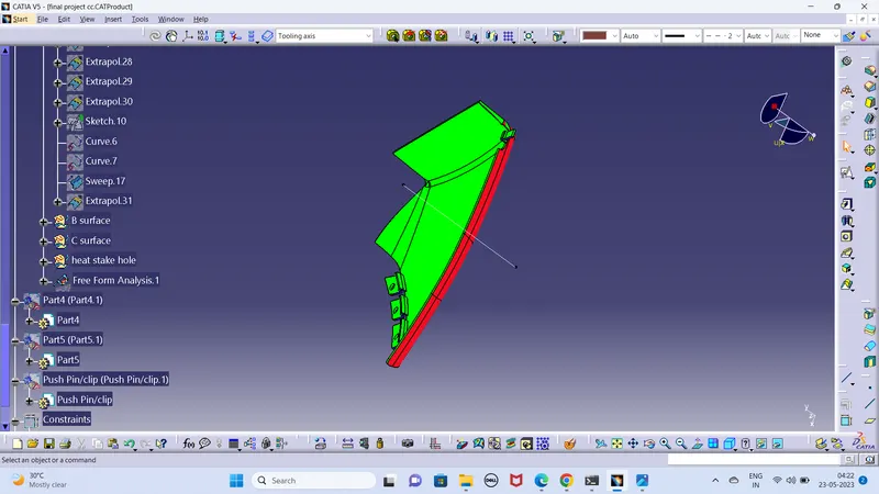
Bottle holder
Class a surface
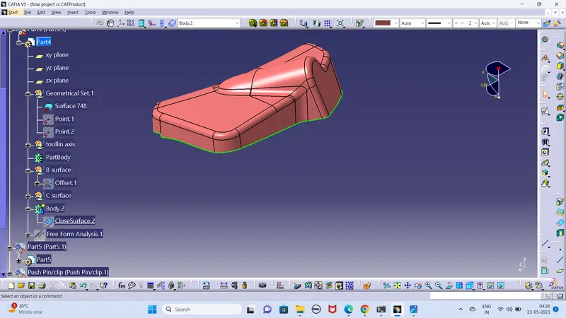
Tooling axis
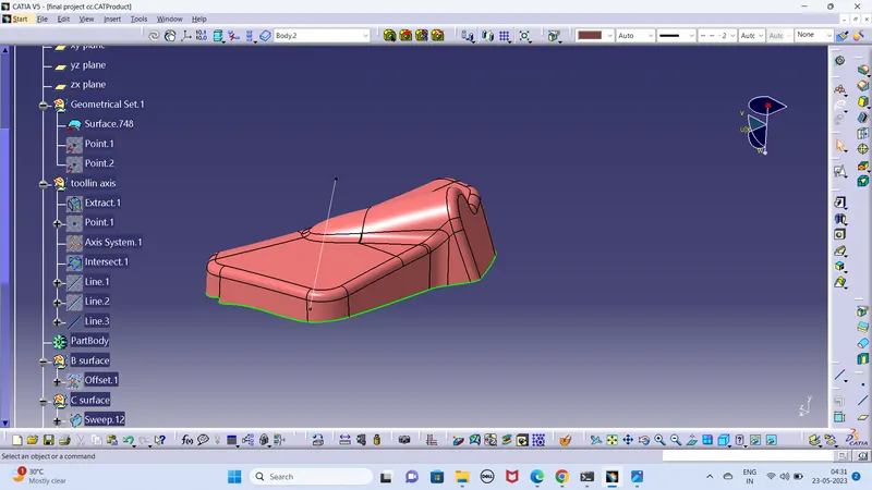
For Class B offset 2.5 mm
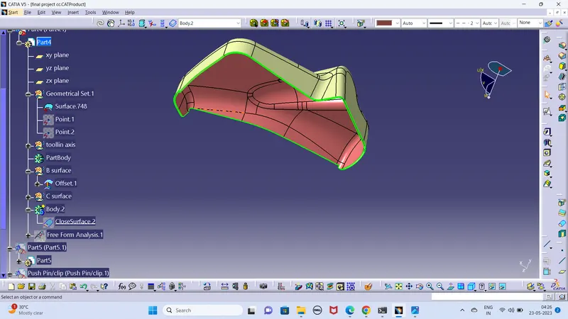
Class C surface
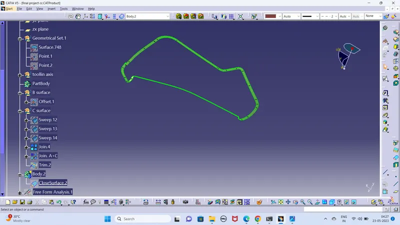
Final C surface
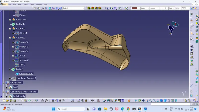
Draft analysis
A Surface
Closed body
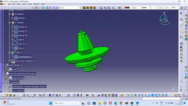
5.PUSH PIN
Push pin which heilp us locating and arresting component of an assembly and it provide alignment in mating parts and also act as various guide of mechanism. They are bascially attached to the dog house.
Conclusion
Thus the Door Trim panel CAD model is created considering the design rules as like in OEM and tier1 companies.