Week 12- Final project
TOOLING AXIS:
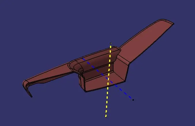
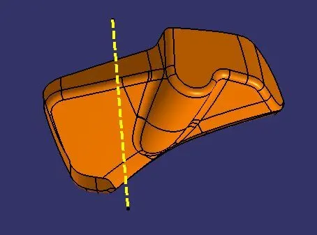
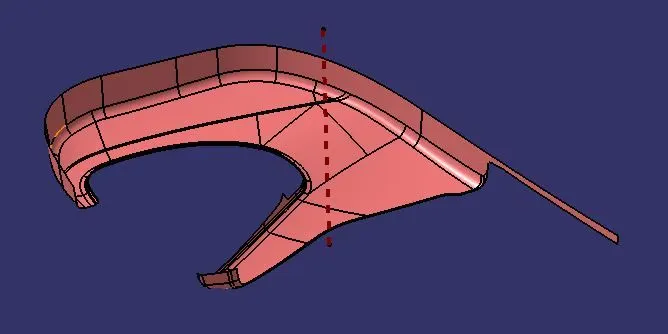
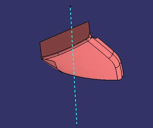
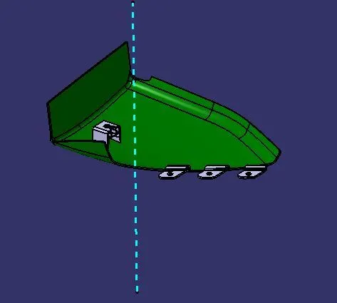
The tooling axis is defined such all the features of the part can be manufactured easily. So here we followed the below steps to create the tooling axis.
- Tooling Axis created for the parts.
- Different ways of tooling axis creation are followed in OEM.
- Bisecting method, point and direction are methods used here.
- The side core axis is also defined when needed.
- These are the photos of the tooling axis.
Arm Rest Tooling Axis
Bottle Holder Tooling Axis
Lower Substrate Tooling Axis
Map Pocket Tooling Axis
DRAFT ANALYSIS:
- The draft is done on the Class A surface of the parts
- Change it to material in a customised view.
- Click the Draft analysis tool and click the surface and align the compass to the tooling axis.
- 3 degrees is the clearing angle
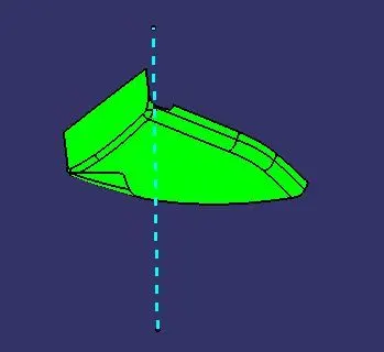
- So here is a photo of cleared (Green) draft.
- A few parts are defective so those sections have not cleared the 3 degrees due to a defect in Class A Surface.
Arm Rest Draft Analysis
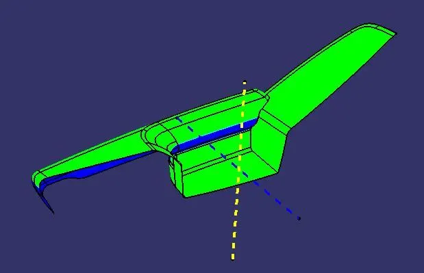
Arm Rest Draft Analysis
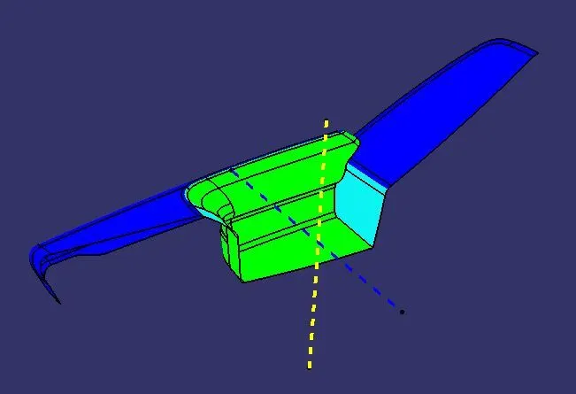
Bottle Holder Draft Analysis
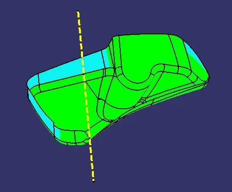
Lower Substrate Draft Analysis
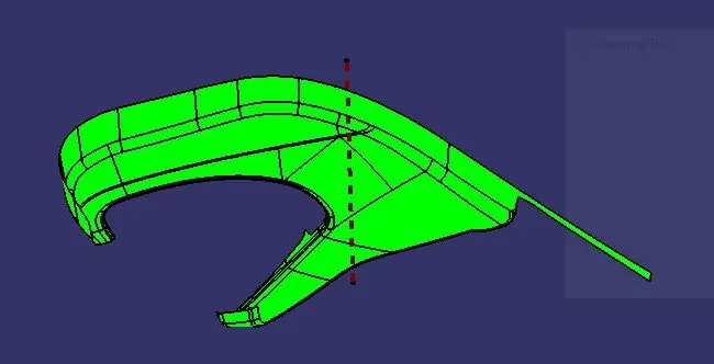
Map Pocket Draft Analysis
B SURFACE:
- B surface is created by using the given Class A surface.
- Apart from complicated faces join other faces.
- Offset it to 2.5mm beneath the Class A.
- Create boundary Create MSS, and Extrapolate for the rest of the sections.
- Trim the extrapolates and join if needed.
- Hence we have created the B surface.
Arm Rest B Surface
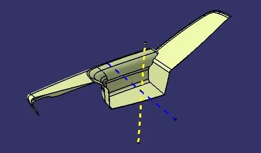
Bottle Holder B Surface
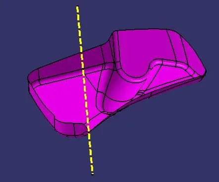
Lower Substrate B Surface
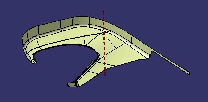
Map Pocket B Surface
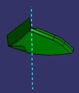
C SURFACE:
- The outer edge of the Class A surface is taken as a reference boundary.
- Sweep is made with reference to the tooling axis with the draft.
- Join the sections and create the C Surface.
Arm Rest C Surface
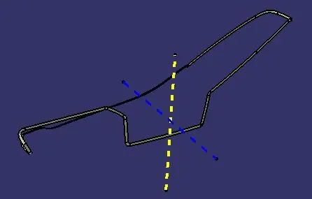
Bottle Holder C Surface
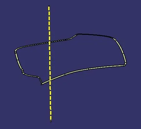
Lower Substrate C Surface
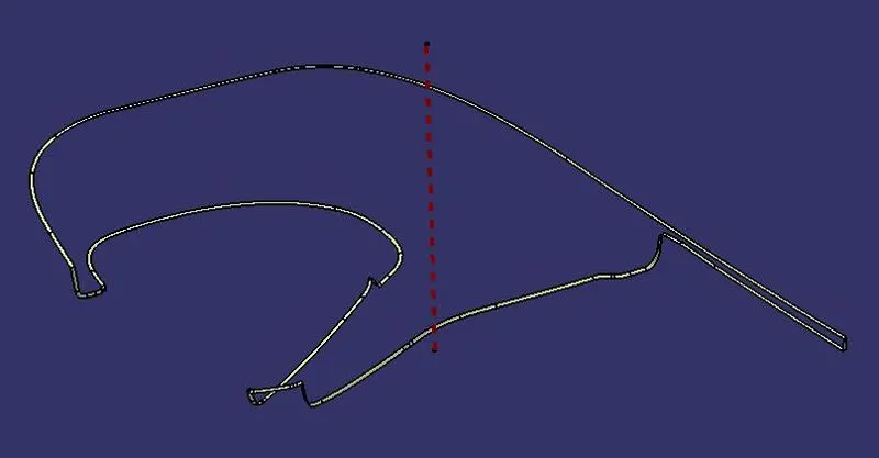
Map Pocket C Surface
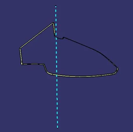
FINAL TRIM:
- Join A and C surfaces.
- Trim with the B surface.
Arm Rest Final Trim
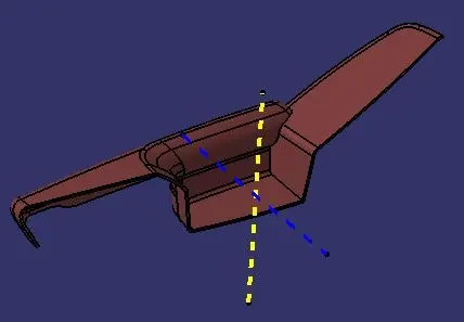
Bottle Holder Final Trim
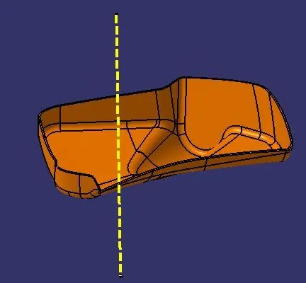
Lower Substrate Final Trim
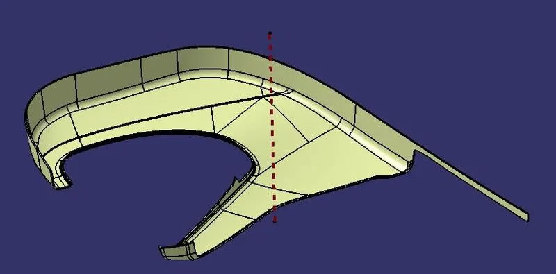
Map Pocket Final Trim
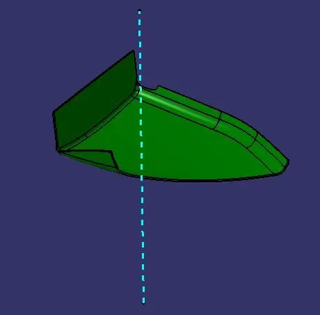
Master Section:
- The master section is used to create the Sketches
- It is then extracted and pad in part design
- Thicken, the split is also used
Arm Rest Engineering Features
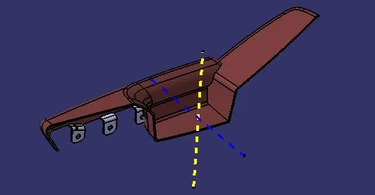
Bottle Holder Engineering Features
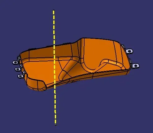
Lower Substrate Engineering Features
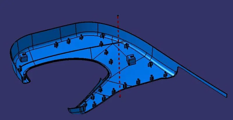
Map Pocket Engineering Features
ASSEMBLY:
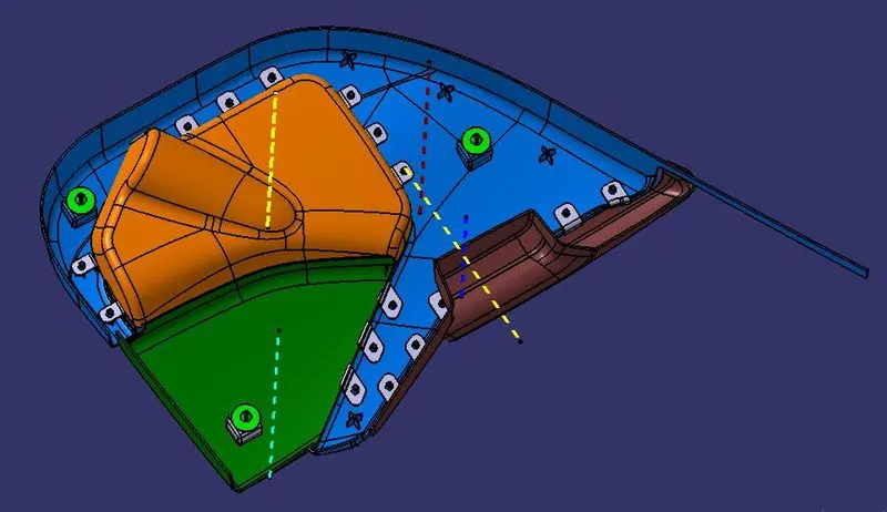
- We then create a product file
- Add the components
- Give constraints and finish the assembly
Final Assembly
CONCLUSION
The door panel was successfully designed by following all design rules used in the automotive industry. All the attachment features are properly placed at different locations.