Week 12- Final project
Aim: Development of Door Trim Panel.
Procedure:
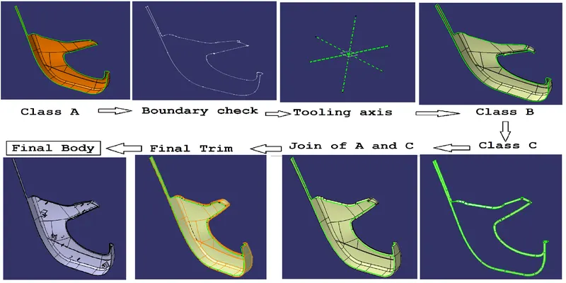
Creation of Tooling Axis--> Modification of Class A surface if required--> Draft analysis of Class A surface--> Creation of Class B surface--> Creation of Class C surface--> Creation of Solid body--> Creation of B side features House --> Draft Analysis of Solid Body.
Different Parts in the Daigram:
1) Arm rest
2) Lower substrate
3) Side rest
4) Bottle Holder
Arm rest:-
1) Modification of class A surface is required. We are suppose to infoem the supperior and clay model department before making any chnages in the Class A surface.
2) Checking the boundary of class A surface
3) Creating the tooling axis by:-
a) Bisecting method: We have to extract the inclined line from class A then we have to line bisecting the two inclined line. then using the bisecting line as a main tooling axis. The line intersecting the flat surface will be points and that point will be used create the side core axis.
b) Extract the point on the flat surface: When we have a flat surface and we can create the point at the center of the surface then checking if all the curve and surface are vissible through that. We should create the side core axis using the same point.
c) Creation of center of gravity and then creating the tooling axis through that point. We are creating the tooling axis through center of gravity because we don't have flat surface on which we can create the point.
We should create the side core axis using the same center of gravity.
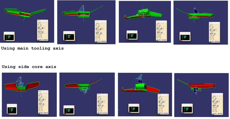
Draft analysis of Class A surface:
Conclusion:
1) When we performe the draft analysis on the Class A we use the Main tooling axis and side core axis.
2) We will select the angle to be 2.9 degree and more as we have provided the draft of 3 degree
Green colour indicate that the angle is more than the 3 degree.
blue colour indicates that the angle is between 0 to 3 degree.
Red colour indicates that the angle is less than 0 degree.
Red colour on the Class A surface indicate that portion of the part will not clear through the tooling axis so we have to use the side core for creating that part.
Process image:-
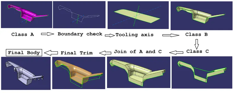
All B side features such as heat stakes, Flanges and 4 way connector are made with the help of master section given in the drawing.
All this features should be on the c surface or at the intersection of b and c surface. they should never be on the Class A surface.
Master Section : ( With Arm rest and lower substrate )
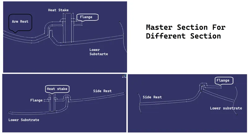
Note: Any flanges will be there in this section. heat stakes, 4 ways connector, Dog house and Push pins will be on Lower substrate
Different orientation of arm rest: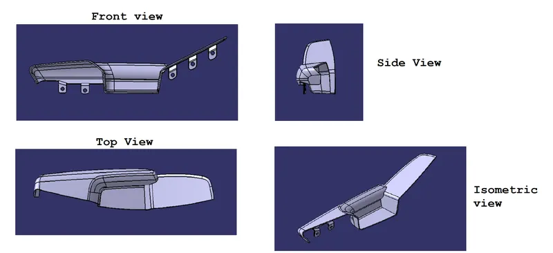
Draft Analysis of arm rest Final product:
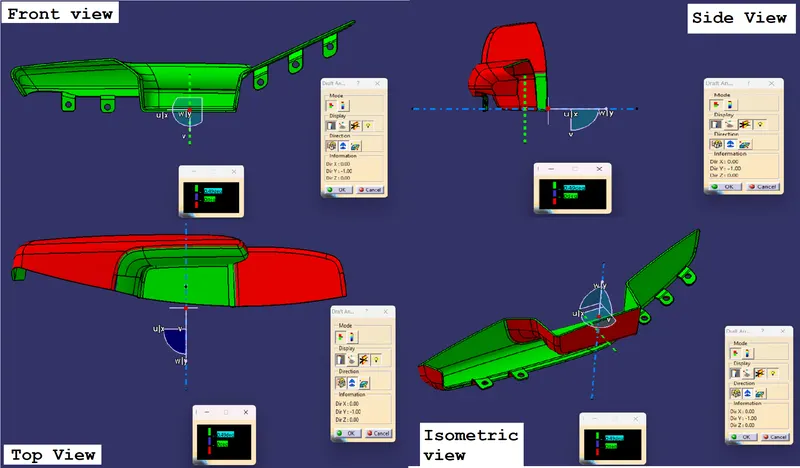
Conclusion of Draft analysis:
1) When we performe the draft analysis on the Arm rest we use the Main tooling axis and side core axis.
2) We will select the angle to be 0.45 degree and more as we have provided the draft of 0.5 degree
Green colour indicate that the angle is more than the 0.45 degree.
blue colour indicates that the angle is between 0 to 0.45 degree.
Red colour indicates that the angle is less than 0 degree.
Red colour on the Arm Rest surface indicate that portion of the part will not clear through the tooling axis so we have to use the side core for creating that part.
Lower substrate:
1) Class A surface
2) Checking the boundary of class, A surface
3) Creating the tooling axis by: -
a) Bisecting method: We have to extract the inclined line from class A then we have to line bisecting the two inclined line. then using the bisecting line as a main tooling axis. The line intersecting the flat surface will be points and that point will be used create the side core axis. We have used this method in arm rest to create the tooling axis.
b) Extract the point on the flat surface: When we have a flat surface and we can create the point at the centre of the surface then checking if all the curve and surface are visible through that. We should create the side core axis using the same point.
c) Creation of centre of gravity and then creating the tooling axis through that point. We are creating the tooling axis through centre of gravity because we don't have flat surface on which we can create the point.
We should create the side core axis using the same centre of gravity. We will use this method to create the tooling axis in this part.
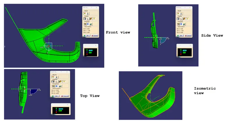
Draft anaylsis of Class A surface:
Process to create the part:
Creating the B side features:
All the procedure is same but we have to create the B side features such as dog house, heat stake and 4-way connector in this part and also this part will determine the location of the all the b side feature. Basically there has to be a gap of more than 50mm in between any feature and features should not interfere on any main part.
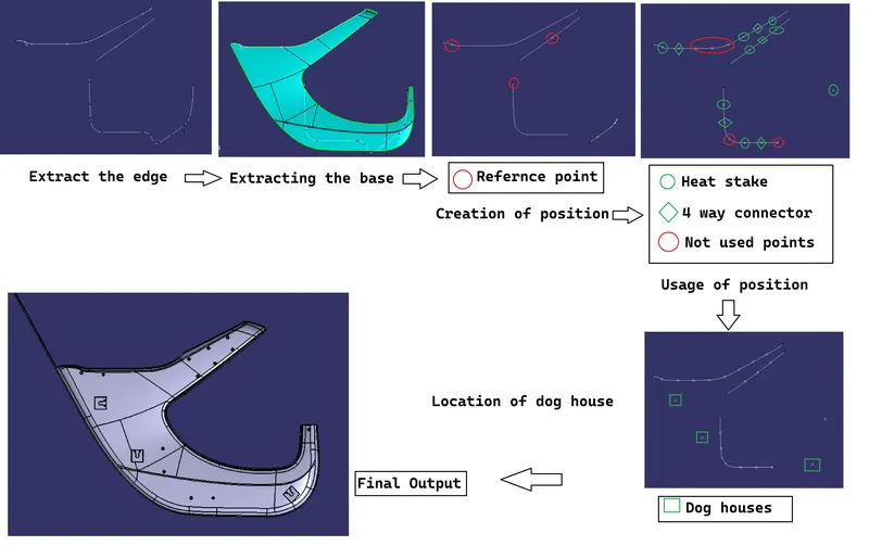
a) Extracting the edges and a base surface for projection from the Class B surface of the lower substrate and a creating a reference point using master section.
b) Projecting the line created from the extract on to the base and making them intersect with the point created.
c) Creating the series of points on the line and using that as a reference to create the all B side features. some of the points will not be used as they are interfering other parts.
d) Dog house will be used to Assemble the push pins.
Different orientation of lower substrate:
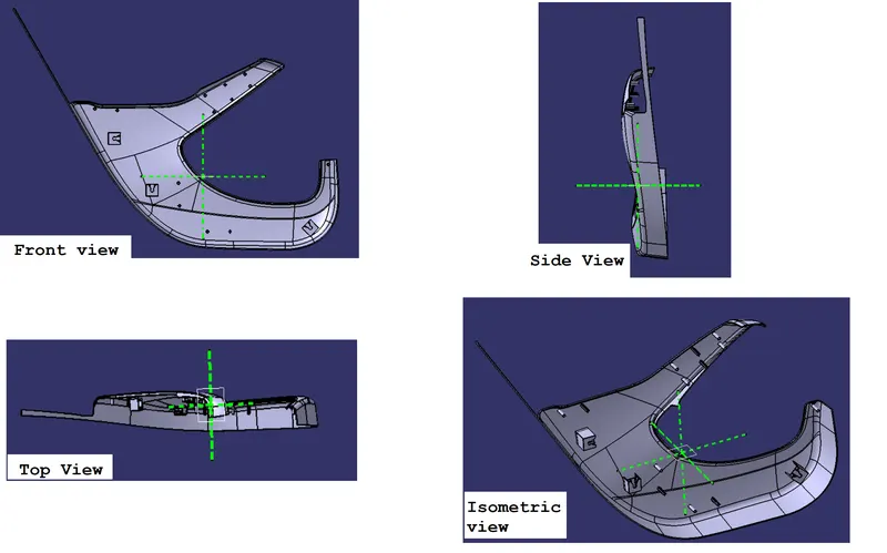
Draft Analysis of lower subsrate:
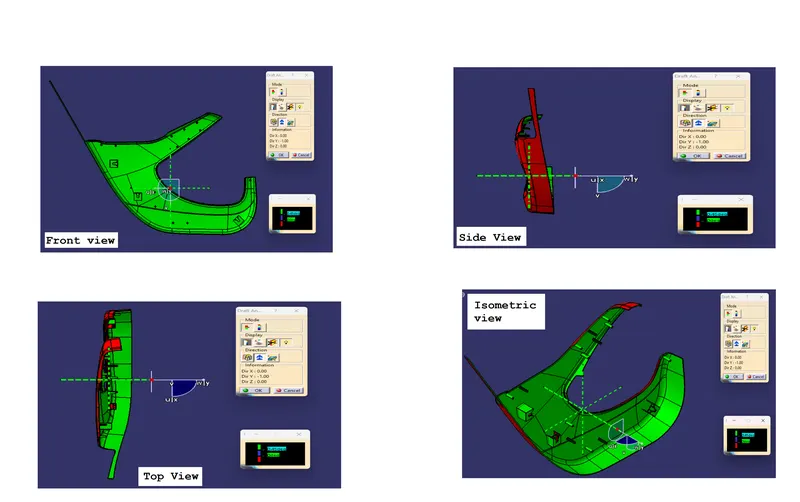
Conclusion of Draft analysis:
1) When we performe the draft analysis on the Lower substrate we use the Main tooling axis.
2) We will select the angle to be 0.45 degree and more as we have provided the draft of 0.5 degree
Green colour indicate that the angle is more than the 0.45 degree.
blue colour indicates that the angle is between 0 to 0.45 degree.
Red colour indicates that the angle is less than 0 degree.
Red colour on the Lower substrate indicate that portion of the part will not clear through the tooling axis so we have to use the side core for creating that part. for example we will use side core axis for clearing the inside portion of dog house.
Side rest:
1) Class A surface
2) Checking the boundary of class, A surface
3) Creating the tooling axis by: -
a) Bisecting method: We have to extract the inclined line from class A then we have to line bisecting the two inclined line. then using the bisecting line as a main tooling axis. The line intersecting the flat surface will be points and that point will be used create the side core axis.
b) Extract the point on the flat surface: When we have a flat surface and we can create the point at the centre of the surface then checking if all the curve and surface are visible through that. We should create the side core axis using the same point.
c) Creation of centre of gravity and then creating the tooling axis through that point. We are creating the tooling axis through centre of gravity because we don't have flat surface on which we can create the point.
We should create the side core axis using the same centre of gravity. We will use this method to create the tooling axis in this part.
Draft anaylsis of Class A surface: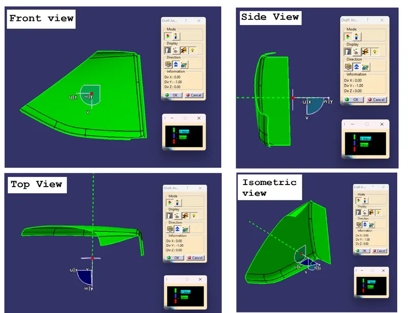
Conclusion:
1) When we performe the draft analysis on the Class A we use the Main tooling axis and side core axis.
2) We will select the angle to be 2.9 degree and more as we have provided the draft of 3 degree
Green colour indicate that the angle is more than the 3 degree.
blue colour indicates that the angle is between 0 to 3 degree.
Red colour indicates that the angle is less than 0 degree.
Red colour on the Class A surface indicate that portion of the part will not clear through the tooling axis so we have to use the side core for creating that part.
Process of solid body creation:
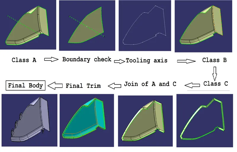
Creation of B side features:
All B side features such as heat stakes, Flanges and 4 way connector are made with the help of master section given in the drawing.
All this features should be on the c surface or at the intersection of b and c surface. they should never be on the Class A surface.
Master Section : ( With Side rest and lower substrate )
Note: Any flanges will be there in this section. heat stakes, 4 ways connector, Dog house and Push pins will be on Lower substrate
Different orientation of Side rest:
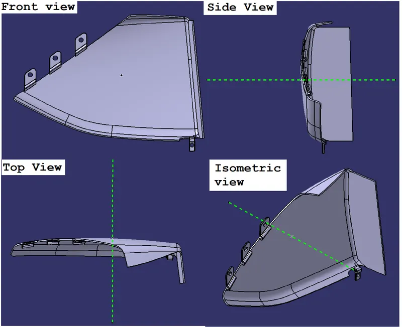
Draft analysis of Solid body:
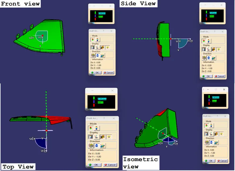
Conclusion of Draft analysis:
1) When we performe the draft analysis on the Side rest we use the Main tooling axis.
2) We will select the angle to be 0.45 degree and more as we have provided the draft of 0.5 degree
Green colour indicate that the angle is more than the 0.45 degree.
blue colour indicates that the angle is between 0 to 0.45 degree.
Red colour indicates that the angle is less than 0 degree.
We have provided the draft of 0.5 degree on the flanges, so we have to check the draft analysis of 0.45 degree.
Bottle holder:
1) Class A surface
2) Checking the boundary of class, A surface
3) Creating the tooling axis by: -
a) Bisecting method: We have to extract the inclined line from class A then we have to line bisecting the two inclined line. then using the bisecting line as a main tooling axis. The line intersecting the flat surface will be points and that point will be used create the side core axis. We have used this method in arm rest to create the tooling axis.
b) Extract the point on the flat surface: When we have a flat surface and we can create the point at the centre of the surface then checking if all the curve and surface are visible through that. We should create the side core axis using the same point.
c) Creation of centre of gravity and then creating the tooling axis through that point. We are creating the tooling axis through centre of gravity because we don't have flat surface on which we can create the point.
We should create the side core axis using the same centre of gravity. We will use this method to create the tooling axis in this part.
Draft anaylsis of Class A surface:
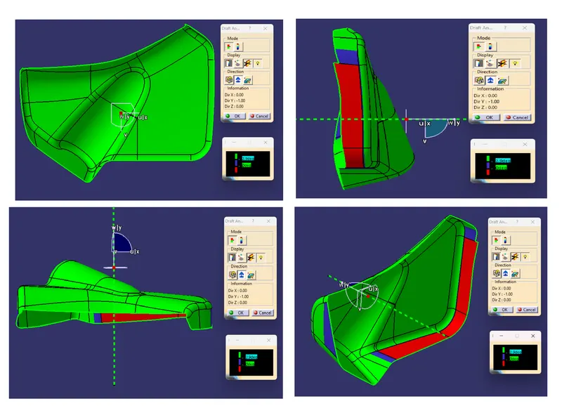 Conclusion:
1) When we performe the draft analysis on the Class A we use the Main tooling axis and side core axis.
2) We will select the angle to be 2.9 degree and more as we have provided the draft of 3 degree
Green colour indicate that the angle is more than the 3 degree.
blue colour indicates that the angle is between 0 to 3 degree.
Red colour indicates that the angle is less than 0 degree.
Red colour on the Class A surface indicate that portion of the part will not clear through the tooling axis, we cannot make any chnages in the class A surface we just need to highlight error the respective department regarding this.
Process of solid body creation:
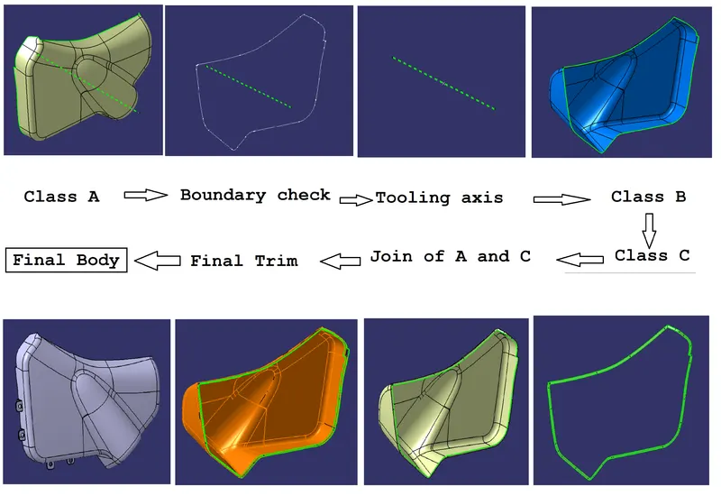
Creation of B side features:
All this features should be on the c surface or at the intersection of b and c surface. they should never be on the Class A surface.
Note: Any flanges will be there in this section. heat stakes, 4 ways connector, Dog house and Push pins will be on Lower substrate
Different orientation of Bottle holder :
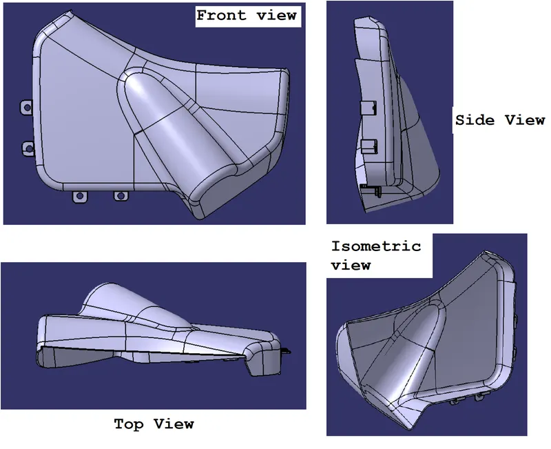
Draft analysis of Solid body:
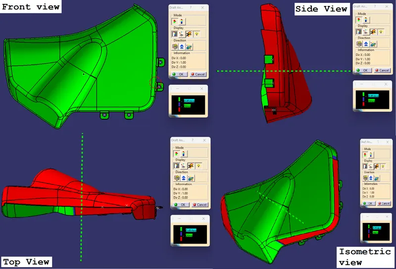
Conclusion of Draft analysis:
1) When we performe the draft analysis on the Bottle holder we use the Main tooling axis.
2) We will select the angle to be 0.45 degree and more as we have provided the draft of 0.5 degree
Green colour indicate that the angle is more than the 0.45 degree.
blue colour indicates that the angle is between 0 to 0.45 degree.
Red colour indicates that the angle is less than 0 degree.
We have provided the draft of 0.5 degree on the flanges, so we have to check the draft analysis of 0.45 degree.
Different orientation of Final Assembly :
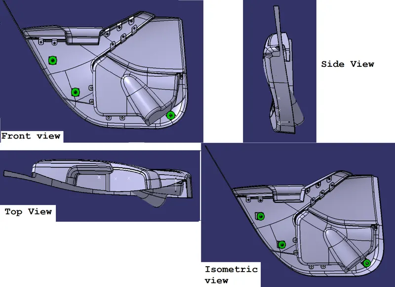
Drafted orientation of Final assembly:
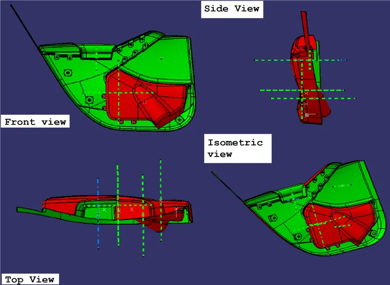
What have we learned from this Project?
1) how can we create the flanges from different methodswith the help of master section and there positioning of the b side features.
2) how to create the full assemble with the help of master section
3) We have used the closed surface feature to create solid body and flanges
Thanking you for provide a chance to enhance our skills with such a competative project.
Please find the attached folder which contains all the part files and product file for reference.