Week 12- Final project
FINAL PROJECT - DOOR TRIM DESIGN
AIM
To create the Door trim panel's CAD model considering the inputs given by following the design rules and OEM standards.
ABSTRACT
The project explains the steps and procedures followed while developing the Door Trim Panel of a car using CATIA V5.
Using the class A surface, need to create the tooling axis, class B surface, and class C surface. From that, it needs to create a solid body. In that solid body, needs to create the engineering features like Ribs, Loators, Dog house, and Heat stakes.
Finally, the draft analysis can be done on the components, to check the manufacturability of the components.
INTRODUCTION
Automotive Plastic Trim:
The design of Automotive Interior and Exterior plastic components is called Trims. The plastic components that you see inside the car are the Interior. Ex: Dashboard, Instrument Panel, Doors, seating, and pillars. Plastic components that you see outside of a car are Exterior. ex: bumper, light assembly, hoods.
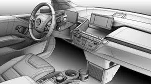

Door Trim:
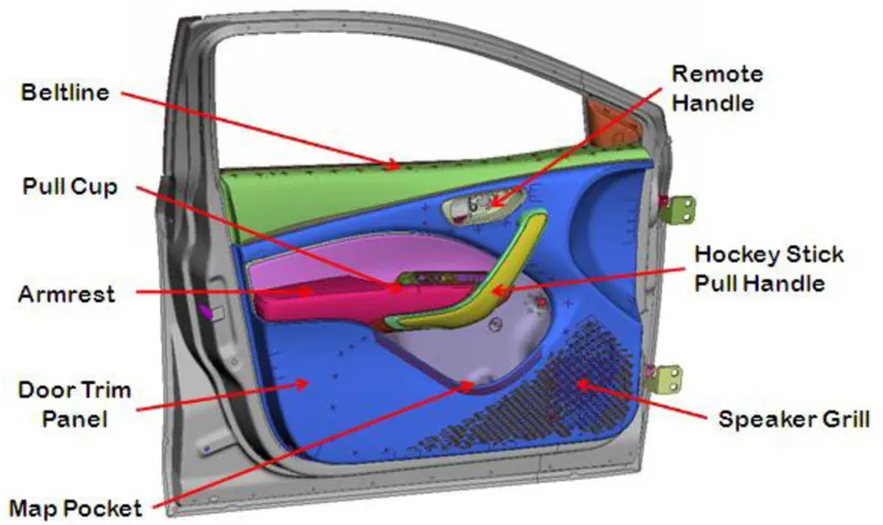
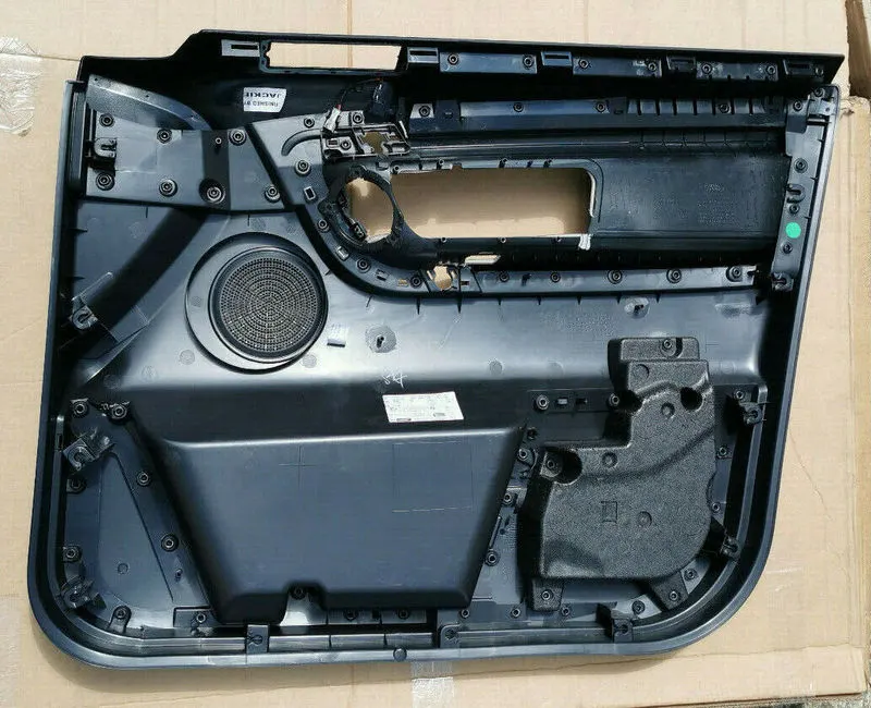
The door trim is an interior trim of an automobile, which is incorporated with the door panels. This door trim gives an aesthetic look to the automobile doors and also provides space for electrical works on its B side or engineering side.
The door panel covers internal parts like the window regulator, the power window motor, and the wiring. It is attached to the sheet metal part of the door. It is designed differently based on the design of the sheet metal part of the door. Besides its aesthetic look, it also has many functional features attached to it such as an armrest, bottle holder, speaker attachment, etc. In older cars, door panels used to be made out of cardboard and upholstered with material that matches the rest of the upholstery within the cabin.
GIVEN INPUTS
The given input consists of master sections and class A surfaces of the door trim. The door trim consists of four sub-elements, which are
- Armrest
- Map pocket
- Bottle holder
- Door lower substrate
- Push clip
Given Class A surfaces:
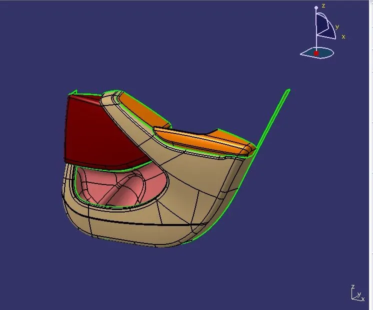
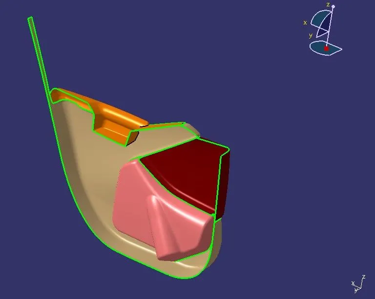
ARMREST CLASS A SURFACE
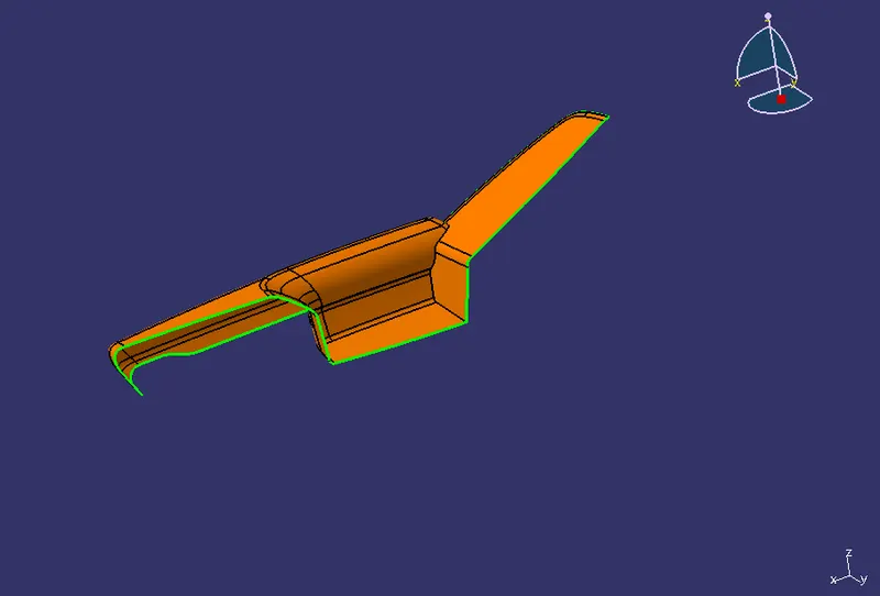
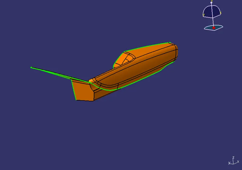
DOOR LOWER SUBSTRATE CLASS A SURFACE
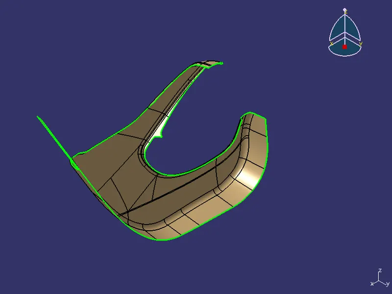
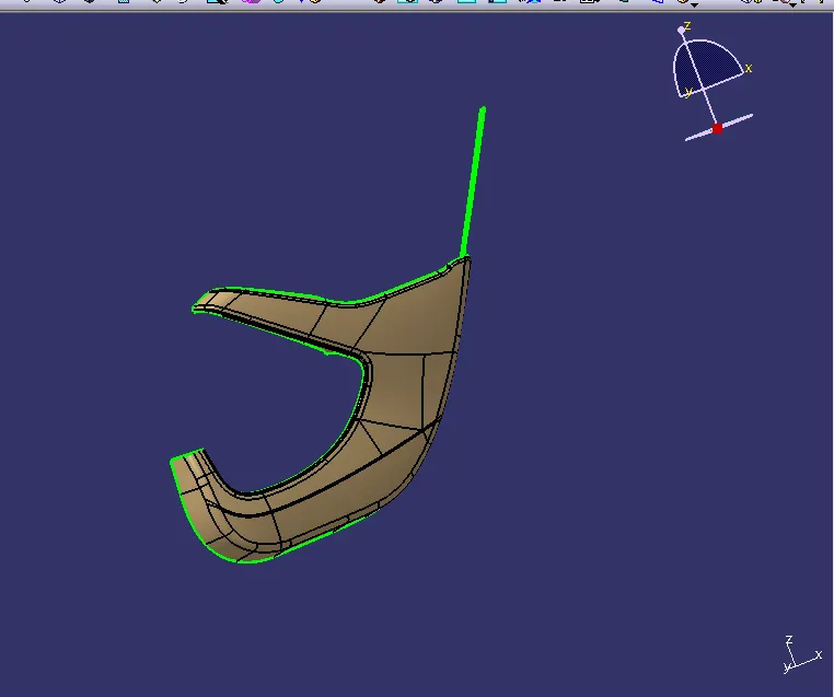
MAP POCKET CLASS A SURFACE
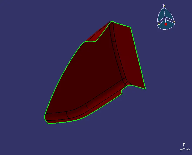
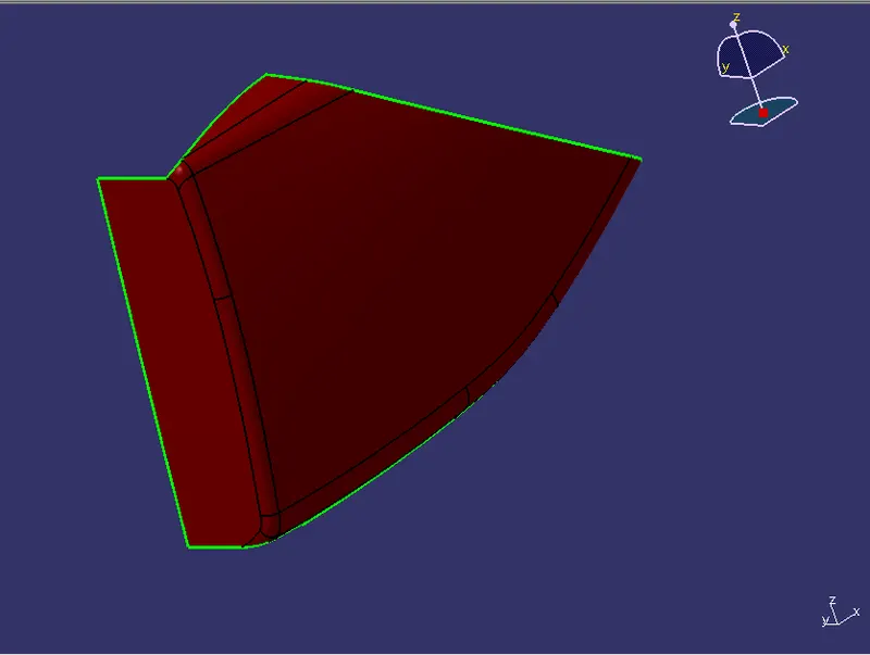
BOTTLE HOLDER CLASS A SURFACE
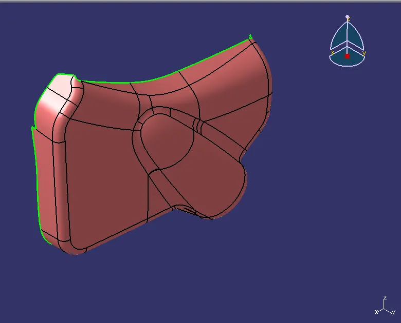
MASTER SECTION
Master Sections are the guides for design requirements that shape the component after the technical styling of Class A Surfaces.
Master Sections are parameterized model of the vehicle body that outlines the guidelines for the NPD Team
Master sections are the guides for design requirements that decide the component packaging after technical (Styling, Concept, or Class-A) surfaces.
The given Master section for the door trim image is attached below.
FOR OVERALL DOOR TRIM
IMPROVING CLASS A SURFACE:
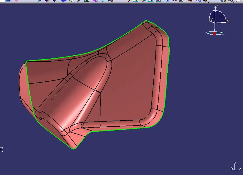
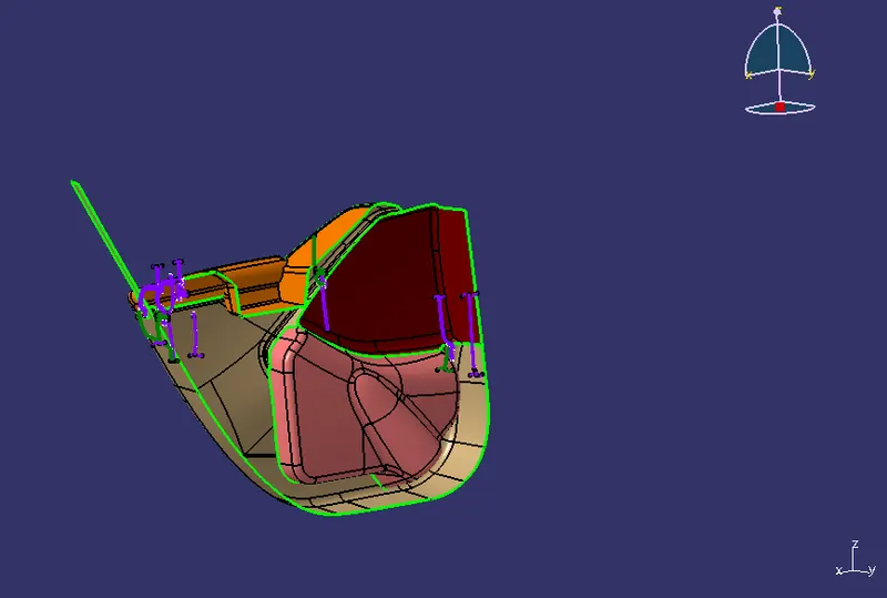
First of all to check the boundary connectivity of the given Class - A surface. To ensure this select join definition tool, it creates a boundary around the edges of the class-A surface. To double ensure that, select the boundary definition tool, which also creates the boundary around the edges of the class-A surface. Disassemble the boundary and check if there is any gap between the boundary. If any discontinuity in the given class A surface, we need to inform to the class A designer regarding the discontinuity. So, that we need to improve the given class A surface with the surface tools.
FOR DOOR SUBSTRATE
Here the lengthy portion is not needed for the given door trim. So, Removed the extra portion in the door substrate. Attached screenshot below.
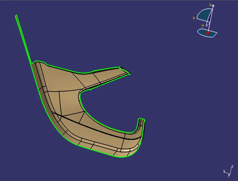
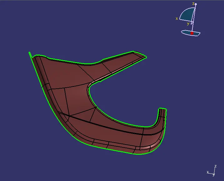
GIVEN CLASS A SURFACE FOR DOOR SUBSTRATE IMPROVED CLASS A SURFACE FOR DOOR SUBSTRATE
FOR ARMREST
Here the surface curve is not in a continuous manner. So, we need to improve the patch at the corner and removed the small fillet. Attached screenshot below.
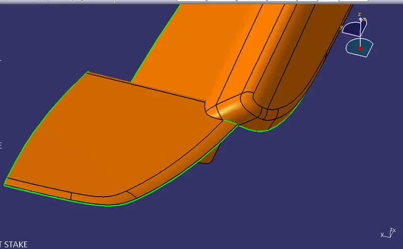
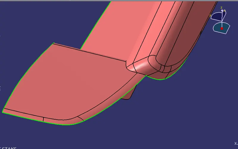
TOOLING AXIS
The tooling axis is defined as the direction in which the mold opens or core and cavity opens and closes.
The selection of the correct tooling axis is important to ensure the component is taken out perfectly and also the cost of the component should be less.
I started by inserting a geometrical set and naming it as a tooling direction. For creating the tooling axis I've analyzed the model and see from which direction I can see the whole model. It is ensured by the draft analysis of the given class A surface with the help of the tooling axis.
TOOLING AXIS CREATION:
To create the tooling axis, create a geometrical set and name it as Tooling axis. Extract a surface on the class - A surface and create a point using the point definition tool. Then Create the Axis system on the point. Create an intersecting boundary along the desired plane, it creates an intersecting curve along the plane. Choose the lines which is parallel to the tooling direction. then create the lines on the interesting curve.
Create a Bisecting line by selecting the two parallel and selecting the point. It creates the Bisecting line between the two lines. Attached screenshot below.
Then come to another side, By following the same procedure in the previous step. In this case, we manually need to create a line that is inclined above the draft angle.
Then finally we need to create the tooling axis. Select the line definition tool with a bisecting line type. Select the two bisecting lines created in the above steps the select the point. It creates a line between these lines. then name it as Tooling axis.
Then publish the Tooling axis and class-A surface
TOOLING AXIS AND SLIDER AXIS FOR ARMREST:
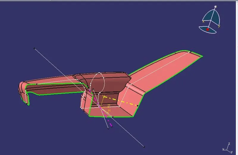
yellow line - MAIN TOOLING AXIS; Pink line - SLIDER AXIS
TOOLING AXIS AND SLIDER AXIS FOR DOOR SUBSTRATE:
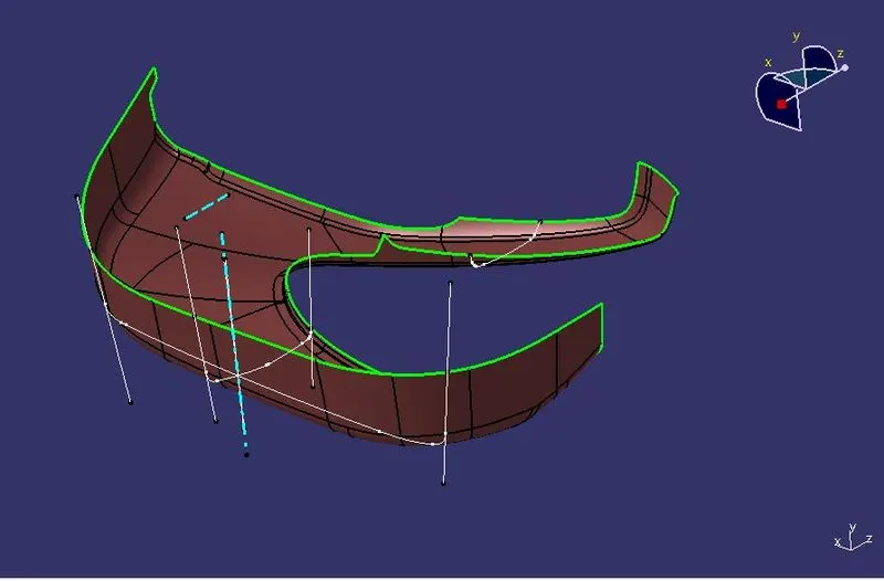
Large cyan line - MAIN TOOLING AXIS; Small cyan line - DOGHOUSE SLIDER AXIS
TOOLING AXIS AND SLIDER AXIS FOR MAP POCKET:
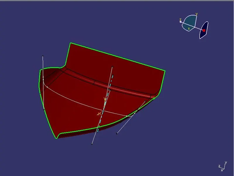
Large cyan line - MAIN TOOLING AXIS
TOOLING AXIS AND SLIDER AXIS FOR BOTTLE HOLDER:
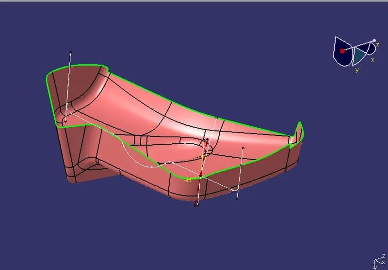
Large Maron colour line - MAIN TOOLING AXIS
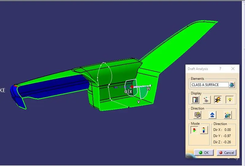
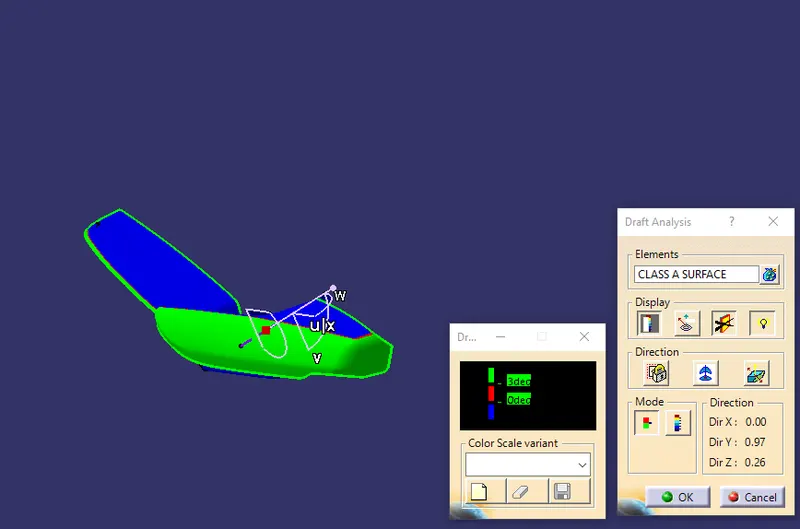
DRAFT ANALYSIS:
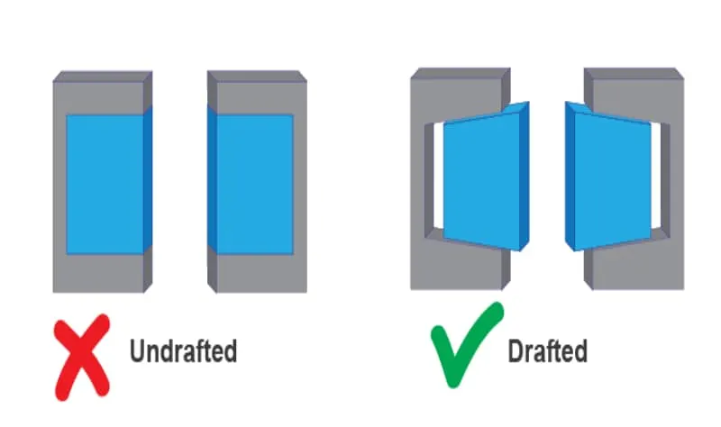
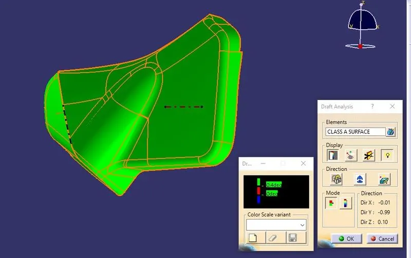
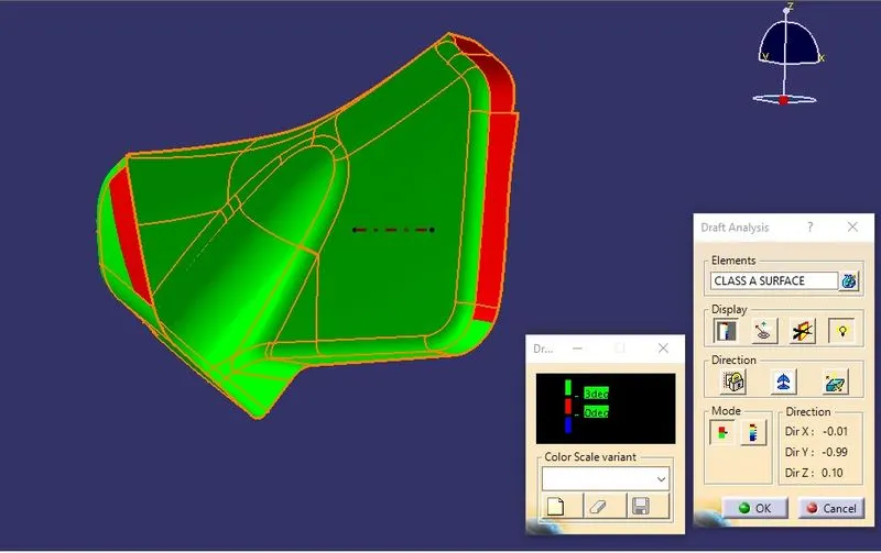
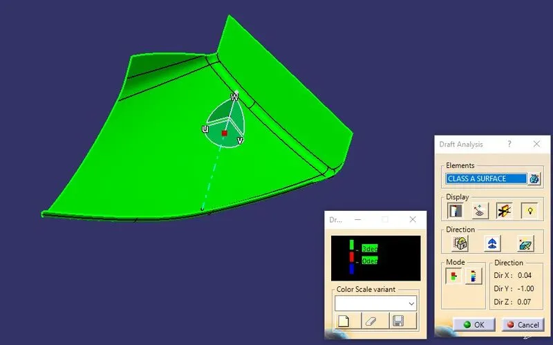
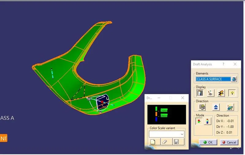
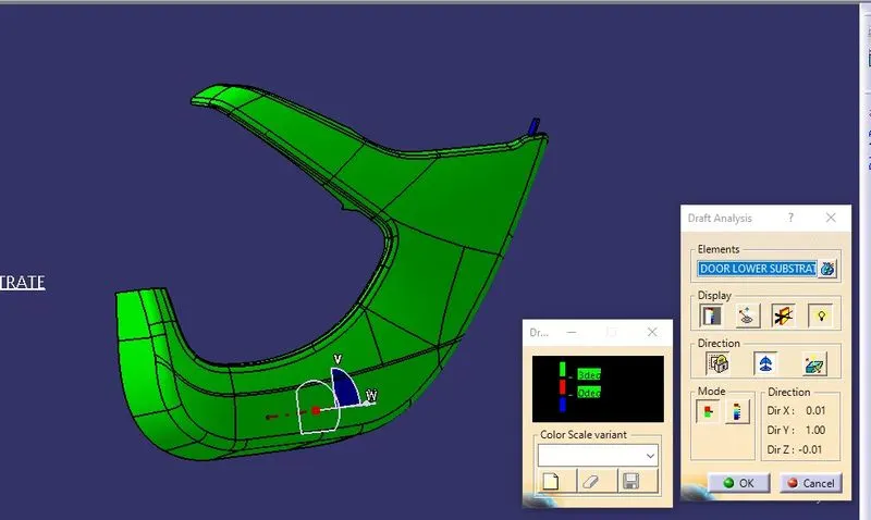
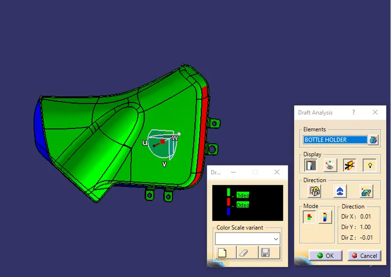
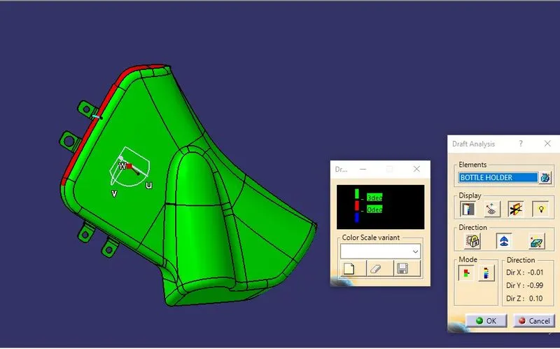
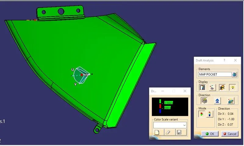
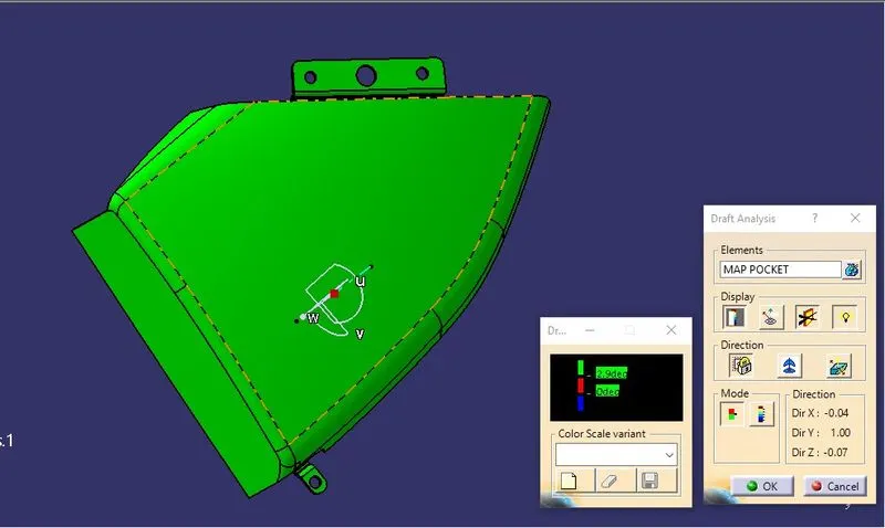
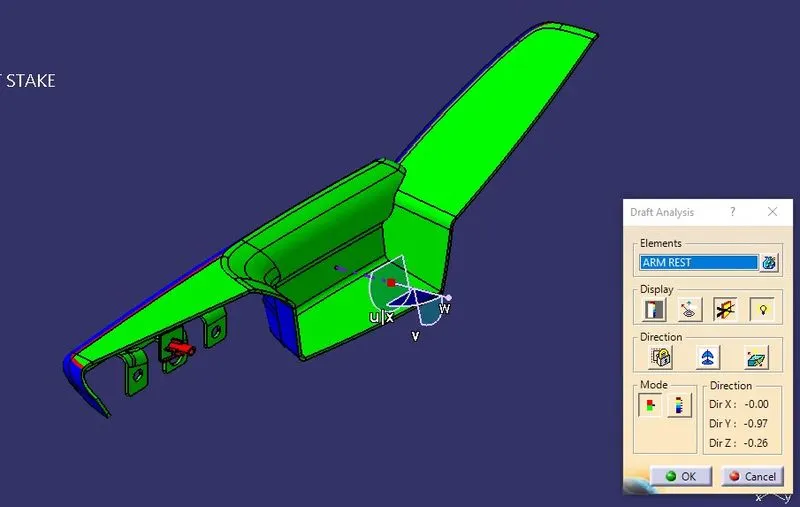
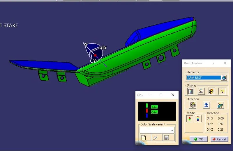
The draft analysis technique is used to analyze whether our part model created in CAD is manufacturable based on the draft condition applied. Here the part should get easily removed from the panel dies.
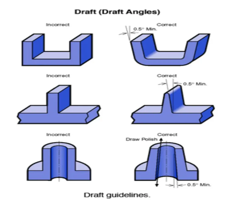
A draft angle refers to the slant applied to the sides of most features of injection molded parts. Positioning of the injection angles is such that they run towards the direction of the mold’s pull and parting line. They help to release the molded parts from the mold easily.
No parts can be ejected from the tool if it is having a straight 90-degree profile from its base surface. A small draft angle is provided to each and every area of the component in order to get easy removal of the component from the tool.
Here we are providing a direction in which components should eject in order to get easy removal of components from the tool. In other words, it also lets us know whether the model is having a draft angle and how much is the draft angle from the tool direction.
Draft analysis for the class A surface:
FOR BOTTLE HOLDER:
FOR MAP POCKET:
FOR DOOR SUBSTRATE:
FOR ARMREST:
CLASS B SURFACE CREATION:
It is a surface that gives thickness from a class A surface. It is similar to a class A surface (just like offsetted from class A surface). All the supporting features of the component will be formed on the B surface only.
so we can say that Class B is an engineering surface and Class A is an aesthetic surface.
For creating the Class B surface I have offset the Class A surface to 2.5 mm which is the thickness of the part according to the master section that is given as the input.
FOR DOOR SUBSTRATE:
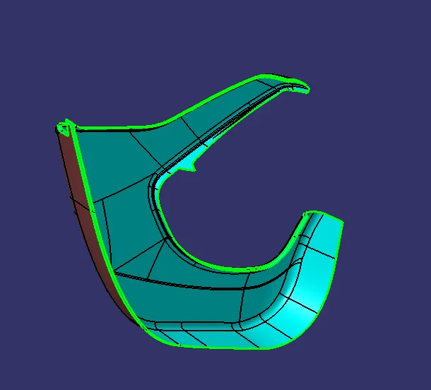
Brown - Class A surface; Cyan - Class B surface.
FOR BOTTLE HOLDER:
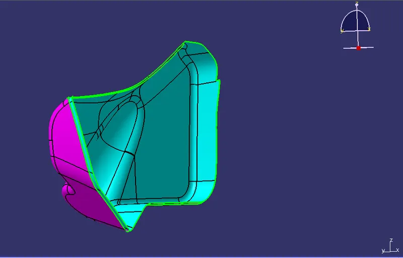
Pink - Class A surface; Cyan - Class B surface
FOR MAP POCKET
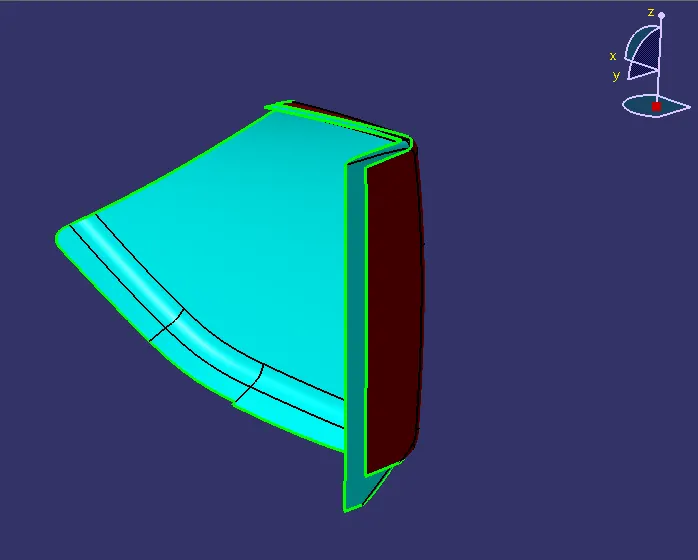
Maron - Class A surface; Cyan - Class B surface.
FOR ARMREST:
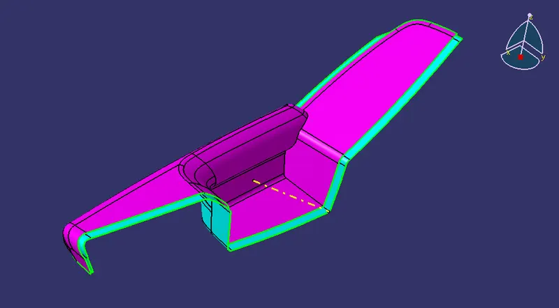
Pink - Class A surface; Cyan - Class B surface
CLASS C SURFACE
Class C surface is defined as the surface which connects the CLASS A and CLASS B SURFACE along the tooling direction.
For creating C surface , we need to ensure the class A surface is parallel to tooling axis or perpendicular to tooling axis.
If the class A curve is parallel to my tooling axis, it is needed to give 3 deg draft angle. In that case, we need to give the sweep surface with along draft direction, by selecting the curve with 3 deg draft direction. Ensure the Class A surface is as aesthetic, So the parting line is not recommended in the Class A surface.
If the class A curve is perpendicular to my tooling axis, We can create the sweep surface with reference surface along with 90 deg angle.
FOR DOOR SUBSTRATE:
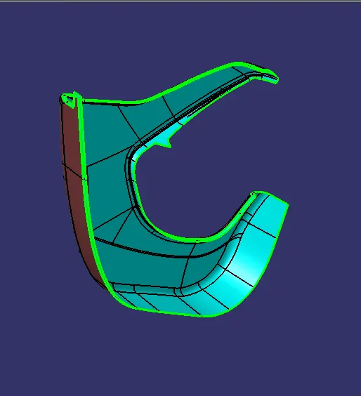
Brown - Class A surface; Yellow - Class C surface.
FOR BOTTLE HOLDER:
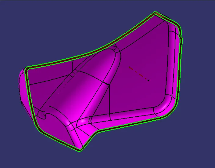
Pink - Class A surface; Maron - Class C surface
FOR MAP POCKET
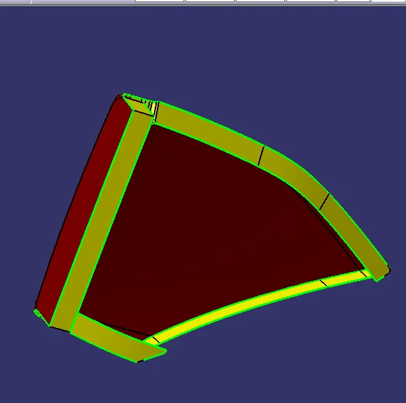
Brown - Class A surface; Yellow - Class C surface.
FOR ARMREST:
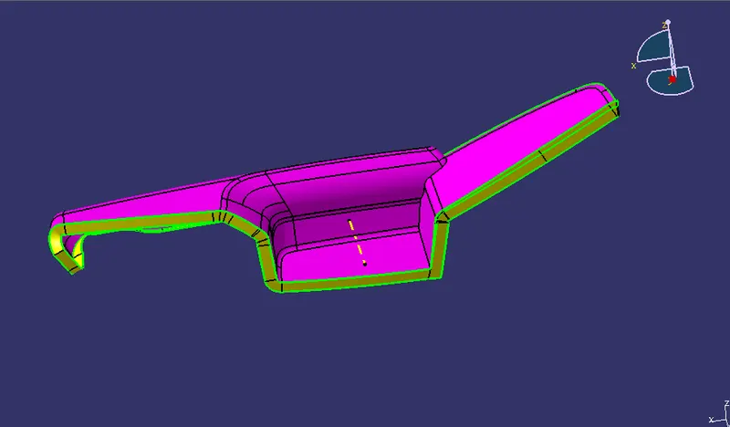
Pink - Class A surface; Yellow - Class C surface
Publication:
Publish the Class A surfaces, Tooling Axis, Slider Axis, Class B surface, Class C surface.
Closed Surface Creation:
For creating the thickened part, we need to combine these Class A, B, and C surfaces together. For that Trim the Class A with Class C surface, then With Class B surface. Finally, we got the Closed surface. Ensure that there will not any open gap in the closed surface, then only we get the thickened part.
By inserting a body, move to the part workbench, using closed surface definition, and select the closed surface. Finally, we got the Thickened part.
ADDING ENGINEERING FEATURES
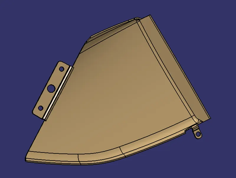
FLANGES
Flanges are the elements that are needed to join different components together.
Based on the given master section flange dimensions and location, I've created the flanges for connecting the other component.
Then I provided the draft and fillets to the flange. The fillets value can be taken from the master section master if given or u can provide a minimum fillet of 1 mm. Coming to the draft value here for the outer map pocket I have provided 3 degrees and but if the flange size is less than u can provide a minimum draft of 0.5 degrees.
IN ARMREST
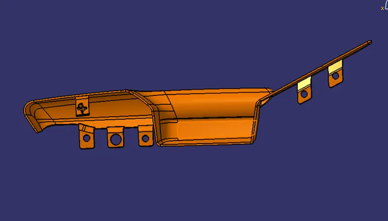
FOR BOTTLE HOLDER
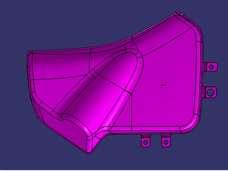
FOR MAP POCKET
LOCATORS
According to 3-2-1 PRINCIPLE:
A workpiece free in space can move in an infinite number of directions. For analysis, this motion can be broken down into 12 directional movements or "degrees of freedom". All 12 degrees of freedom must be restricted to ensure proper referencing of a workpiece.
The 6 axial degrees and 6 radial degrees of freedom. The axial degrees of freedom permit straight-line movement in both directions along the 3-principle axis shown as X, Y & Z. The radial degrees of freedom permit rotational movement, in both clockwise & counterclockwise radial directions around the same three axes.
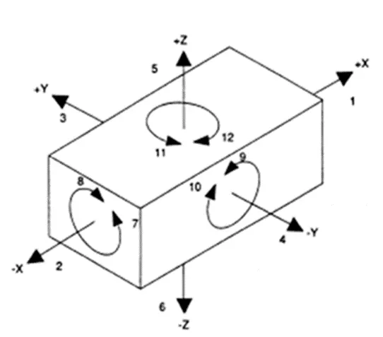
Here I've used 4 Way locators for arresting the degree of freedom of the components
4-WAY LOCATORS:
4-way mean you prevent movement at 2 axes (+X, -X, +Y and -Y) on the plane. Generally, you have a cylindrical pin on the fixture and a circular hole at the workpiece part.
HEAT STAKES
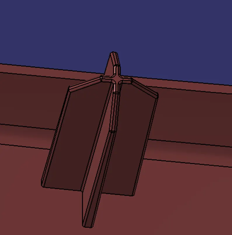
Heat staking is the process to attach two separate components together by melting the base plastic material into a shape that will hold the secondary component. It’s a permanent attachment method that does not require any additional material such as an adhesive or a solvent to make the permanent bond. The only addition is the heat applied to melt the plastic and a tool to shape the plastic to form the mechanical connection.
Heat staking can be done with a precise and rapid operation that also offers repeatable results every cycle. Manufacturing machines can be developed to complete multiple heat-staking operations at once to decrease cycle time. The stakes don’t have to be parallel which makes the design options limitless.
DOG HOUSE
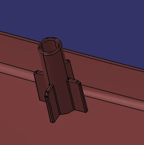
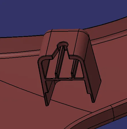
Dog house is an engineering feature used in the plastic trim design. Doghouses are used as supporting features. Sometimes other engineering features like snaps; locators, etc. are mounded on them to increase their strength. Dog houses are subjected to draft analysis to prevent breakage of the component during ejection from the mold cavity. Dog house and other engineering components are built on B-surface.
Design guidelines for dog house:
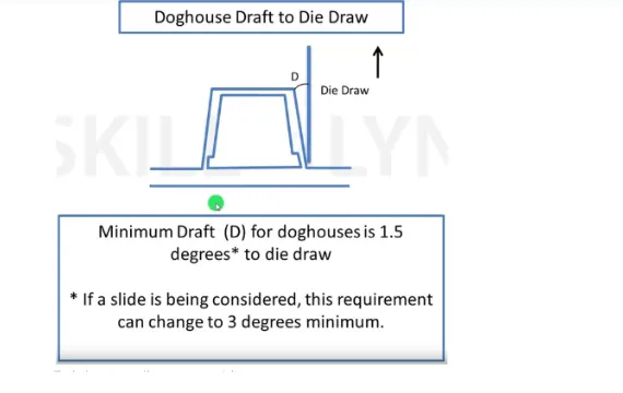
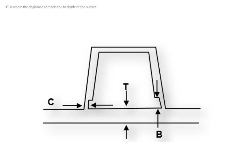
The dog house has only two critical parameters as shown in the above thumb rule.
1. Dog house dimensions can be taken as per the requirement of length or height.
2. Wall thickness at the base of the Dog house ‘C’ should be 40% or less than wall thickness.
3. Height of ‘B’ should be between 3.0 to 6.0 mm
DRAFT ANALYSIS FOR DOG HOUSE:
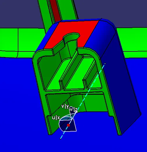
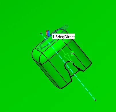
Internal draft angle - 0.5 deg External draft angle - 1.5 deg
PUSH PIN
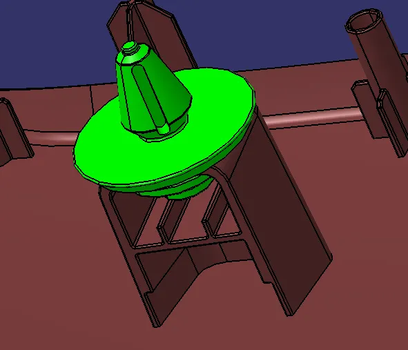
Push pins are used for joining one component to another. These are basically attached to the dog house.
The push pin is also given as a input file.
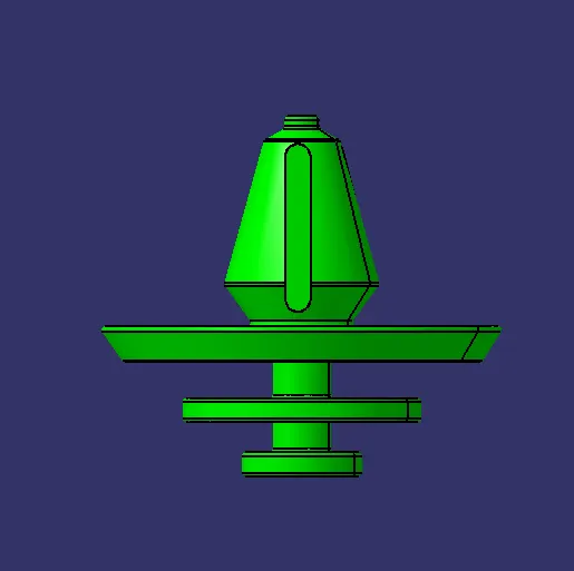
Based on the dimension of push pin, The dog house top portion pocket was made.
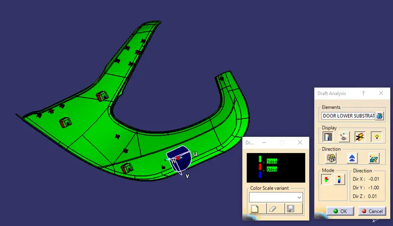
FINAL DRAFT ANALYSIS:
FOR DOOR SUBSTRATE:
FOR BOTTLE HOLDER:
FOR MAP POCKET
FOR ARMREST
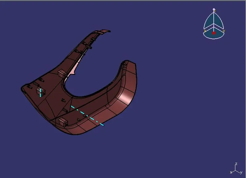
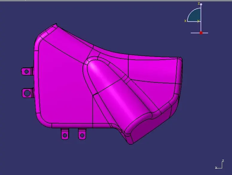
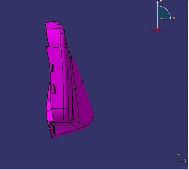
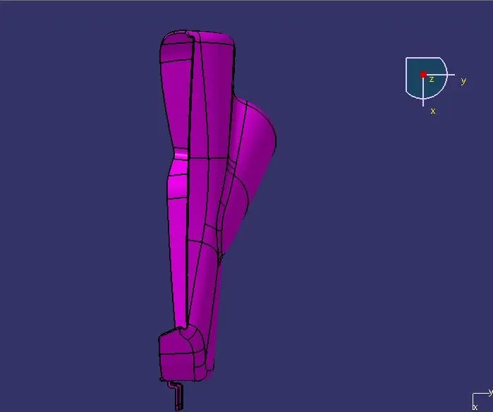
DIFFERENT VIEWS
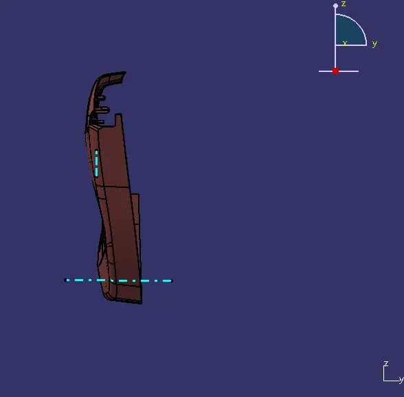
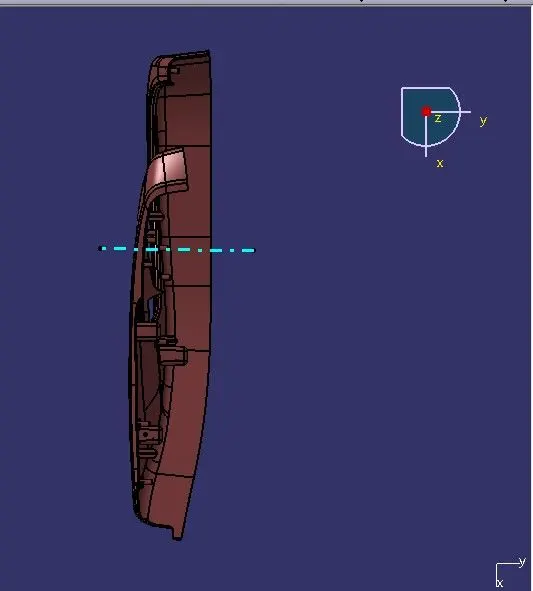
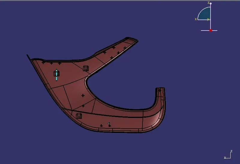
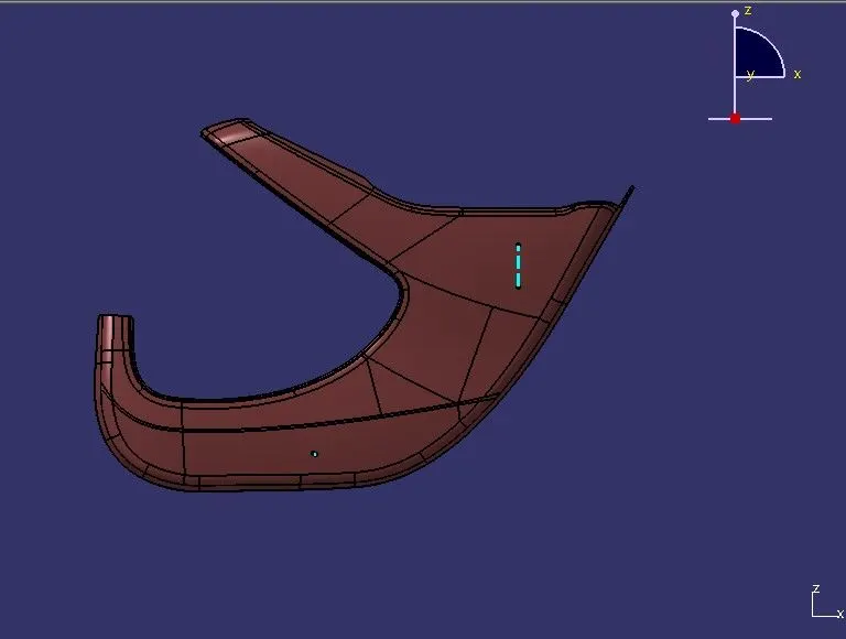
DOOR SUBSTRATE:
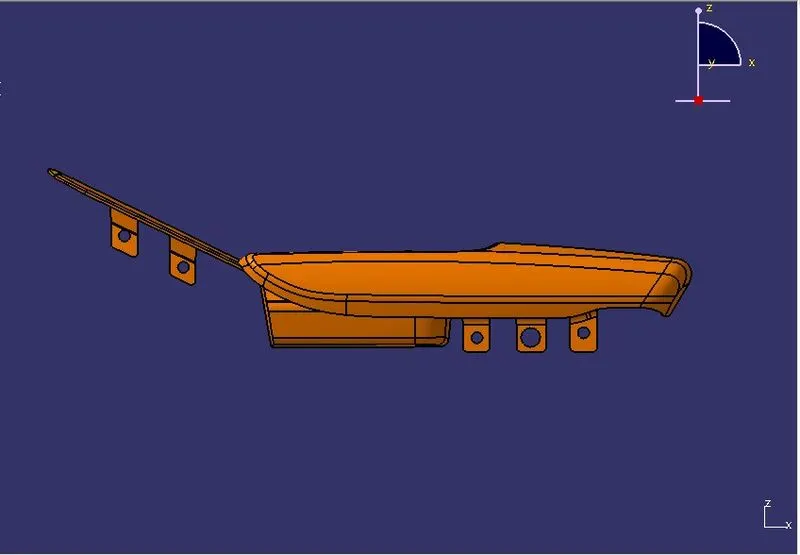
ARMREST
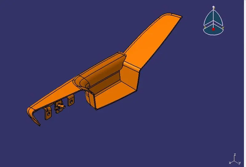
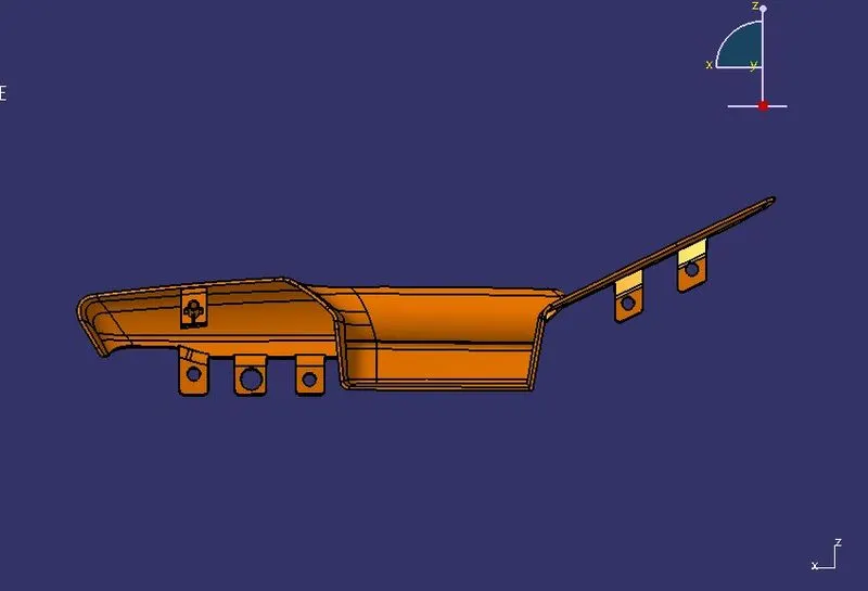
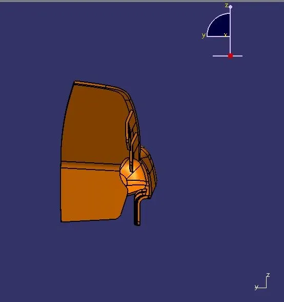
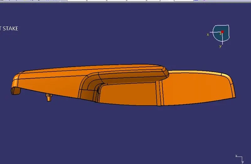
MAP POCKET
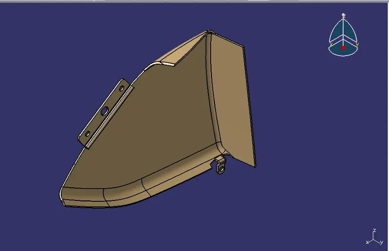
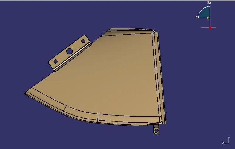
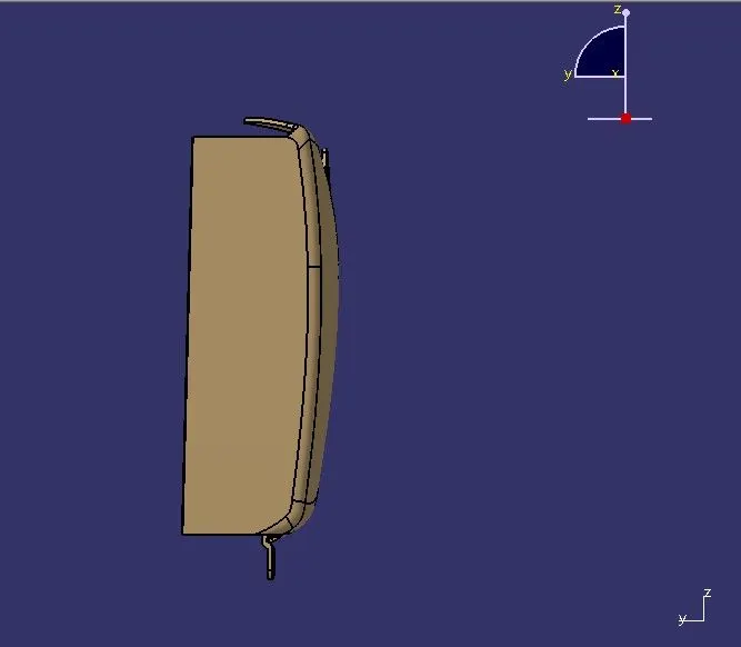
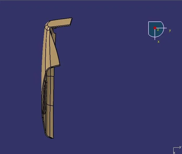
BOTTLE HOLDER
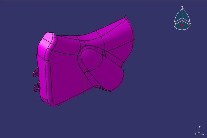
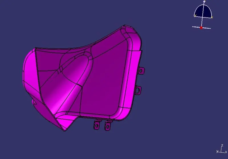
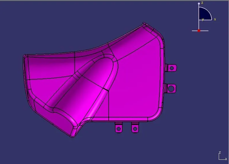
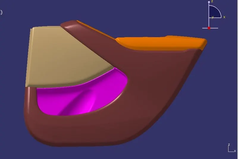
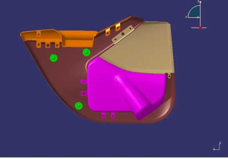
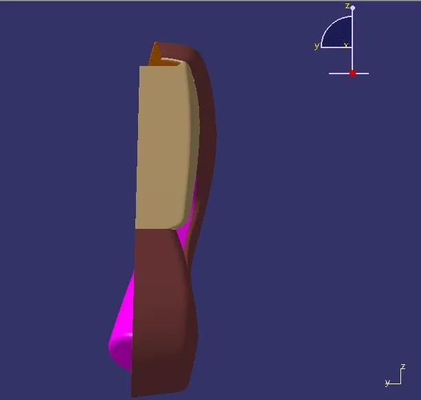
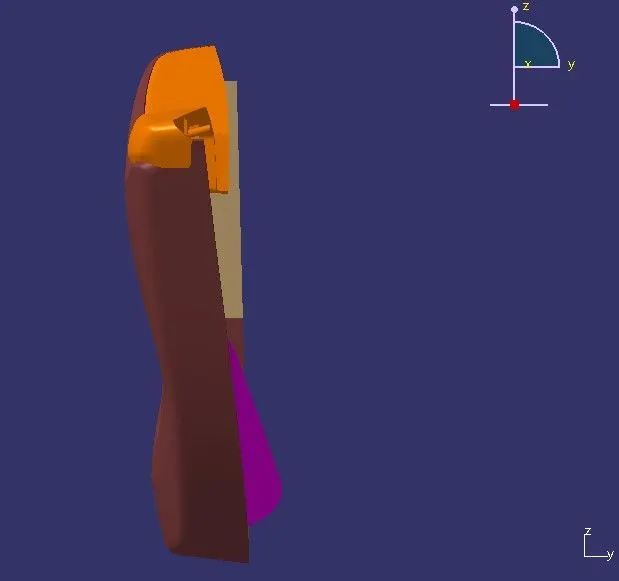
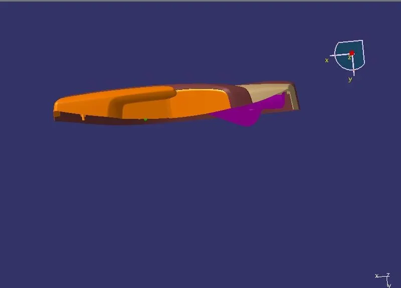
DOOR TRIM
CONCLUSION:
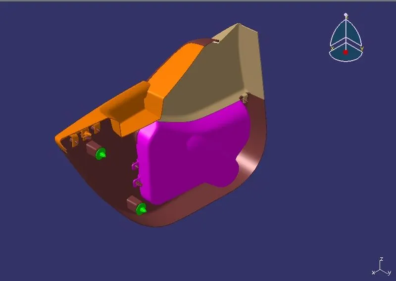
Creation of the car interior door trim is designed using the given class A surface as the input and Class B and C surfaces are created with the help of the Class A surface. By using the given master section attachment features I.e. Heat stakes, Flanges, Dog houses, and Push Clips are created using the design rules.
The draft analysis has been performed to analyze the draft of the component to manufacture easily applying draft to the surface by 3 degrees and 0.5 degrees to the attachment features.
With all data and reports, we can conclude that draft analysis is very important to design any plastic component to mold the plastic easily. The analysis will verify that all surfaces are favorable for being pulled from a cavity. It may also highlight or give insight into defect areas.
The Door trim panel's CAD model by considering the inputs given by following the design rules and OEM standards is created successfully.
Thank you,
Regards,
Premnath Senthil