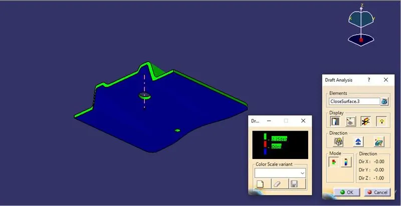
Week 9 - Challenge 1 - Base Bracket Design
REPORT FOR TOOLING AXIS CREATION AND DRAFT ANALYSIS
TOOLING AXIS CREATION:
First I took a look at the given Class - A surface. Then ensured any connectivity of the boundary of Class - A. By ensuring it, I used the join definition and checked the connectivity of the boundary. There is no surface gap in class A.
By double ensuring, I selected the boundary definition and disassemble the boundary. The first design check is completed.
For creating the tooling axis, created a point on the Class-A surface then created a line along the direction perpendicular to Class A. Named as dummy tooling axis.
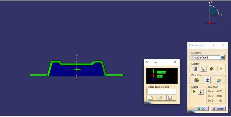
Created an intersect boundary in the Y-Z plane. Attached screenshot below.
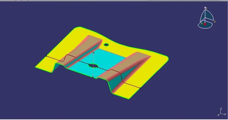
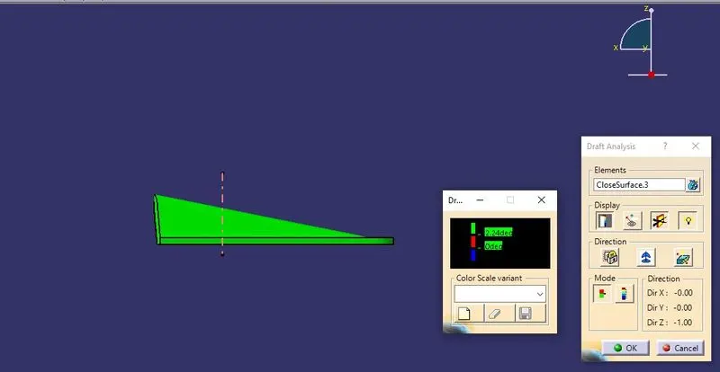
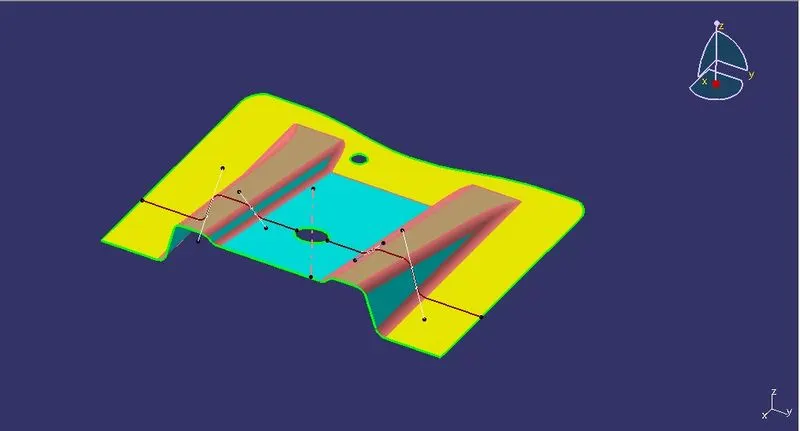
Created lines along the taper curves in the intersect curves on both sides. Then created the Bisecting line by using the lines on both sides. It creates a line in the middle of the two taper lines. And named it TOOLING AXIS. Attached screenshot below.
DRAFT ANALYSIS ON GIVEN CLASS A SURFACE.
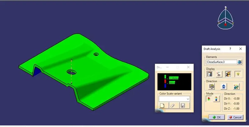
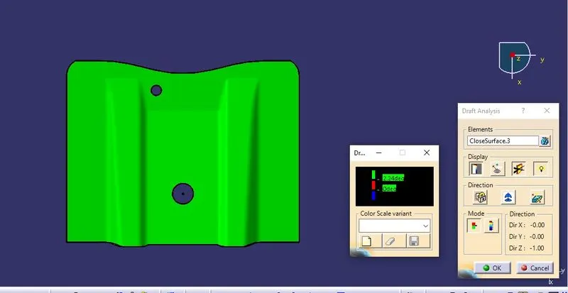
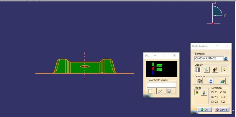
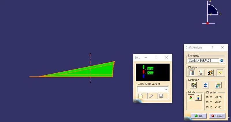
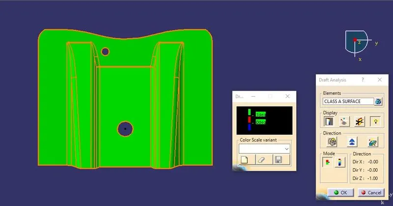
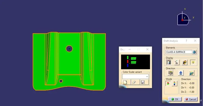
For crating draft analysis, Ensure the component shading is in customise view parameters with material shading. Select the draft analysis tool, select the given class A, then use the compass to position along the draft direction, lock the draft direction the check the component is given with proper draft along the tooling axis. Attached screen shot of the class A surface draft analysis.
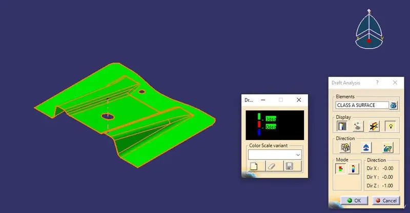
DRAFT ANALYSIS OF CLASS -A SURFACE
DRAFT ANALYSIS OF COMPONENT BASE BRACKET