Week 10 - Challenge 1- Attachment Feature Creation (Ribs & Screw Boss)
REPORT FOR TOOLING AXIS AND DRAFT ANALYSIS FOR CLASS A SURFACE:
TOOLING AXIS CREATION:
First of all to check the boundary connectivity of the given Class - A surface. To ensure this select join definition tool, it creates a boundary around the edges of the class-A - A surface. To double ensure that, select the boundary definition tool, which also creates the boundary around the edges of the class-A - A surface. Disassemble the boundary and check if there is any gap between the boundary.
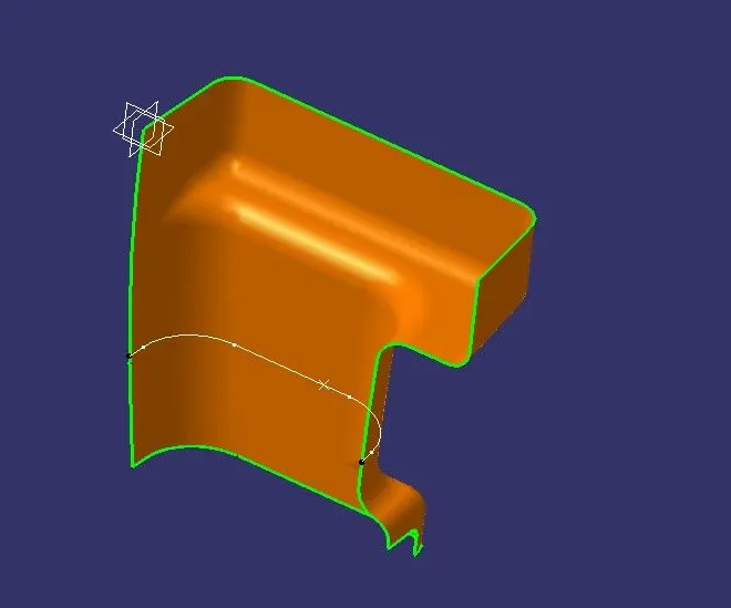
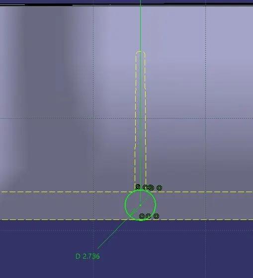
To create the tooling axis, create a geometrical set and name it as Tooling axis. Extract a surface on the class - A surface and create a point using the point definition tool. Then Create the Axis system on the point. Create an intersecting boundary along the Y-Z plane, it creates an intersecting curve along the plane. Choose the lines which is parallel to the tooling direction. then create the lines on the interesting curve. Attached screen shot below.
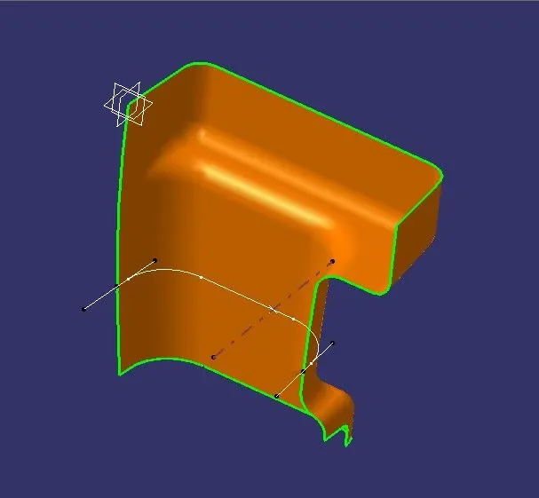
Create a Bisecting line by selecting the two parallel and selecting the point. It creates the Bisecting line between the two lines. Then name it as Tooling Axis. Attached screenshot below.
DRAFT ANALYSIS ON CLASS - A SURFACE:
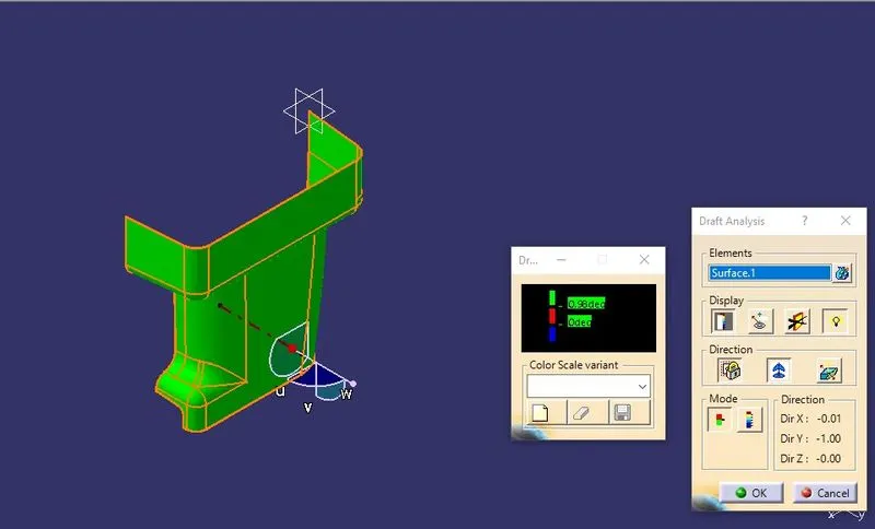
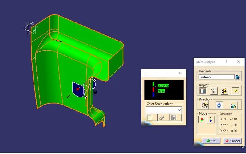
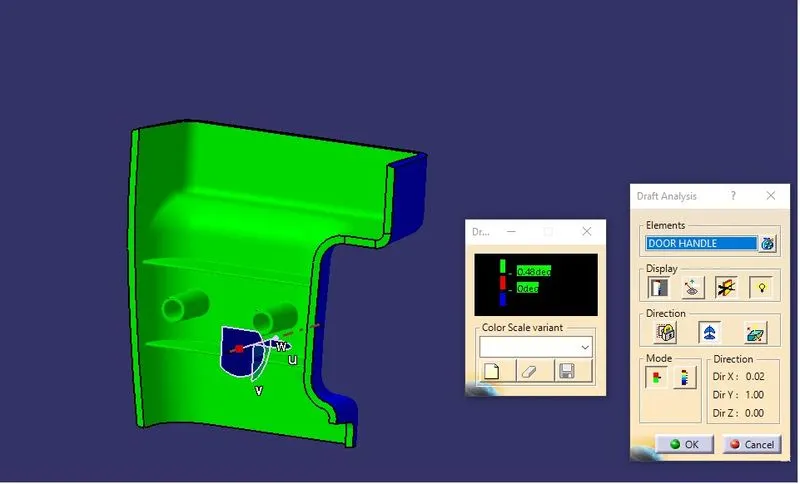
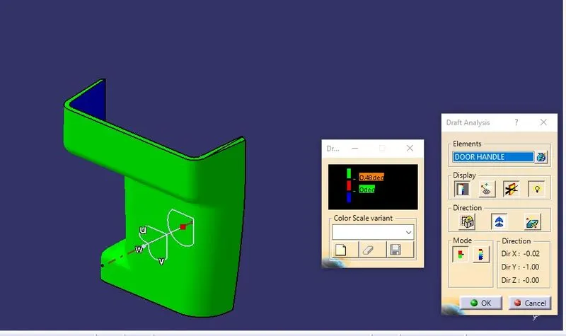
Before creating a draft analysis, ensure the component or surface is in customize view parameters with material shading. Select the Draft analysis tool, and select the component. Drag the compass in the tooling axis. Lock the direction. Then select Ok. Ensure all the faces along the tooling axis are in green color. We got the draft angle for the given class A surface is 0.98 deg. Attached screenshot below.
DRAFT ANALYSIS ON DRILL HANDLE:
RIB ROOT THICKNESS :
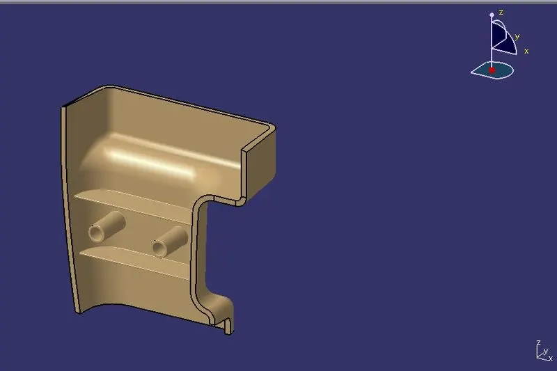
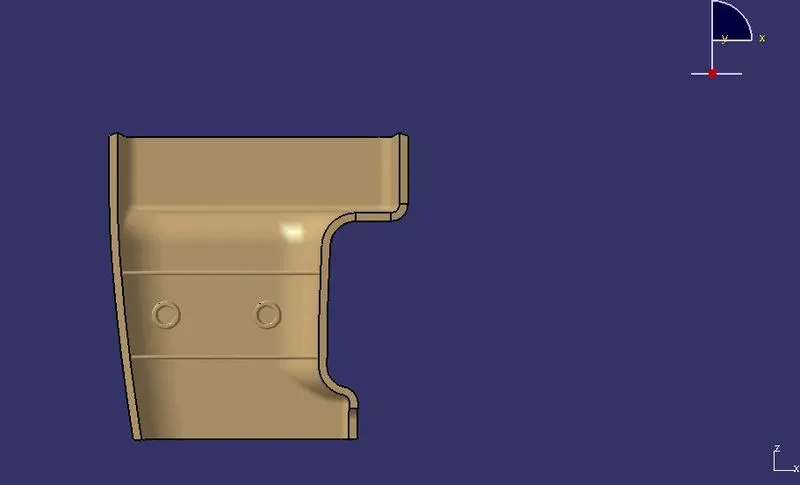
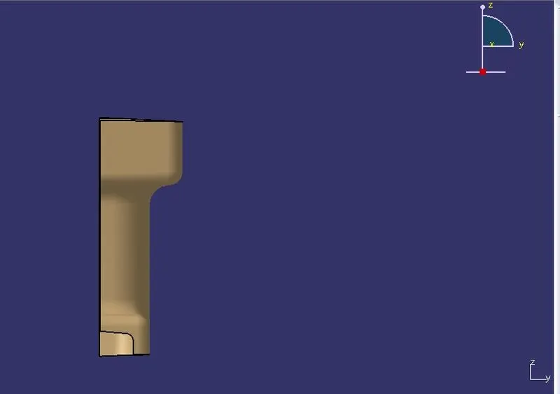
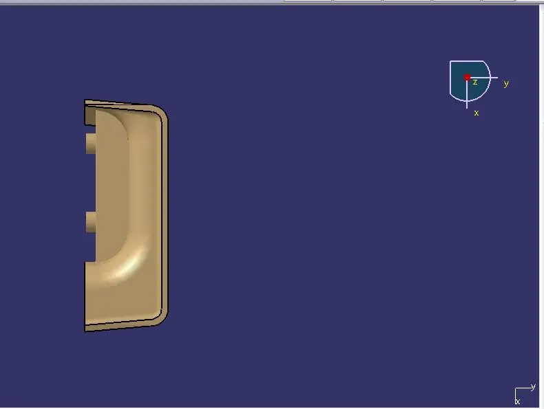
VIEWS OF DRILL HANDLE:
Thank you,
Regards,
Premnath Senthil