Week 12- Final project
Objective: To design the Door Trim panel from the given Class-A Surface in Catia -V5.
Project Overview: Door Trim is the interior component attached to the inferior side of the door. It's a vital component which provides aesthetic look to the interior of the car and also provides features and functions for the passengers. In this project we are going to design the lower portion of the door trim from the given Class-A Surface. Also we would be designing the B-Side Features on the component by following the industry standards and design rules.
Workbench and its Toolbar used:
Generative Shape Design Workbench
- Surface Toolbar
- Wireframe Toolbar
- Operation Toolbar
Part Workbench
- Sketch Based Feature Toolbar
- Dress up Features Toolbar
- Surface Based Feature Toolbar
Theory:
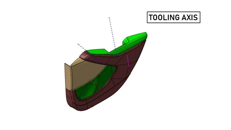
Tooling Axis - Tooling Axis is the direction in which the component will be ejecting after the molding process is completed. The rules of selecting an optimum direction of tooling axis for any particular component is as follows :-
- The direction of the tooling axis should be clearing the maximum number of portions of the component once the molding process is completed.
- The direction of the tooling axis should be selected such that the number of side cores required should be minimum, as inserting side cores causes a rise in production cost.
Draft Analysis - Draft is the inclination given to any particular plastic component’s cavity walls in order to achieve easy ejection, once the process is completed.
- Consider that the draft angle between the plastic component and the core is zero.
- When the molten plastic inside the cavity cools, it sticks to the walls of the core.
- During such zero draft condition, the ejection of the plastic component causes friction between them which might bring damage to both the core and the component.
- This damage further leads to inefficiency in the production & also affects the product’s surface finish.
- Hence, a minimum of ½ to 1 deg draft is provided to help in releasing the component.
- However 3 deg draft is widely accepted as a norm in the industry.
Prerequisites before creating the tooling axis and performing draft analysis-
- Ensure that the Class A surface imported should be a single surface.
- This can be checked using the Boundary tool in the Operation Toolbar.
- If the surfaces are disassembled, join them using Join command which is also found in the Operation toolbar.
Creating any component from Class A Surface ( Overview ) -
- Decide a suitable tooling axis direction and create the Tooling Axis.
- Perform Draft analysis for analyzing whether the drafts on the component follow the industry standards.
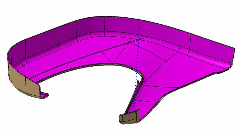
- Create another surface ( B Surface ) offset to the Class-A Surface. The offset distance should be equal to the thickness of the component.
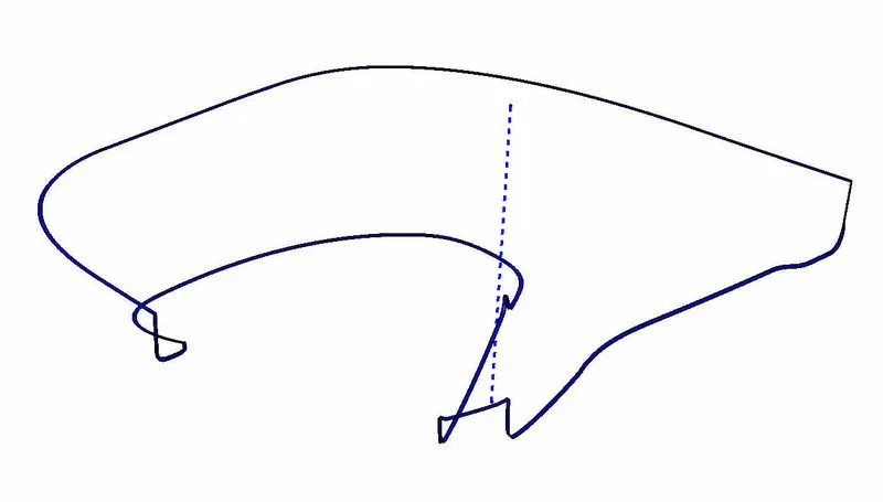
- Create a C- Surface ‘Sweeping’ the boundary of Class-A -Surface along the Tooling Axis.
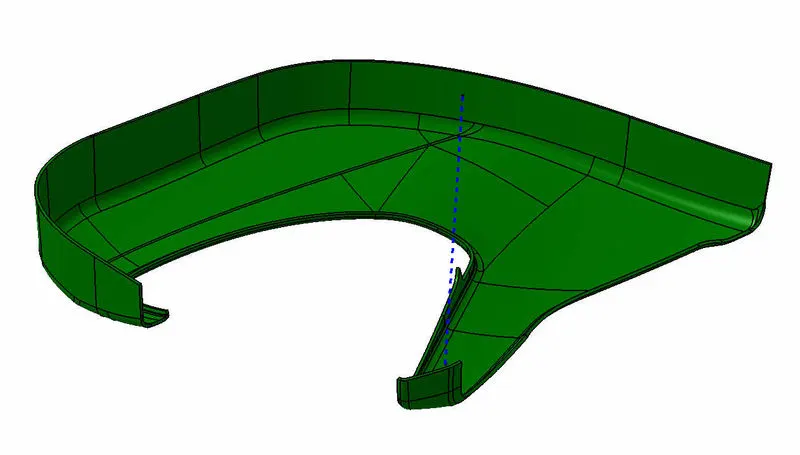
- Trim Class- A surface with B-Surface and C Surface to create a closed surface.
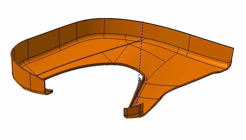
- Finally create the solid part from this surface to obtain the desired component.
Procedure:
I] Visual Analysis of Class-A Surfaces:
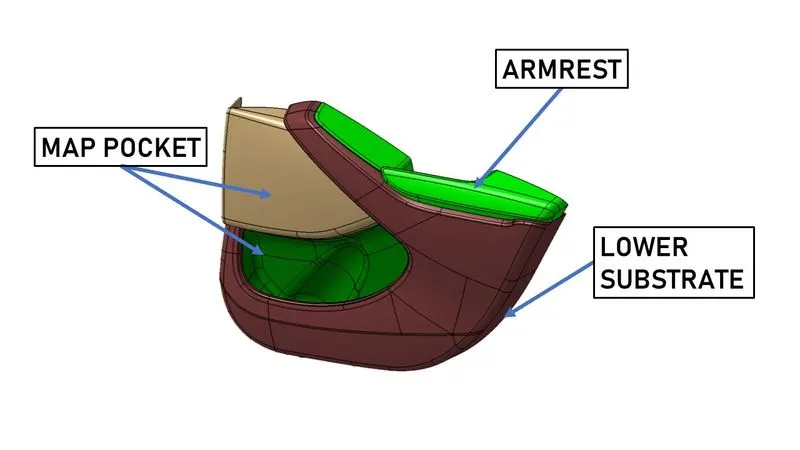
Firstly we observe the Class-A Surface and understand how the component can be manufactured.
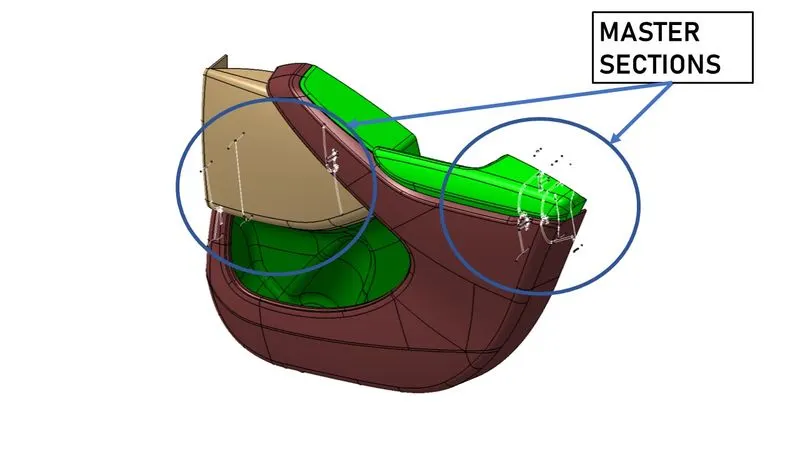
Observing the Master Sections:
II] Creation of Tooling Axis:
- Tooling Axis can be decided using various methods, namely - Bisecting Method, Trial and error basis using Draft Analysis Tool or simple 90 deg to the component.
- In industries, the tooling axis is mainly considered as 90 deg and the Class-A Surface is designed accordingly with proper drafts on the component.
- Wherever necessary the tooling can be modified.
- For our Component we consider the tooling in Y direction , but for the armrest we have used a side core tooling. ( The reason for the same is mentioned under the Draft Analysis Report.)
II] Draft Analysis Of Class-A Surface:
- Draft Analysis is performed on the component in order to check whether the component can be manufactured or not.
- This Draft Analysis tool in Catia allows us to analyze the drafts provided on the surface.
- We can check whether they follow industry standards and if not we can modify it accordingly.
The procedure of Draft Analysis is as follows-
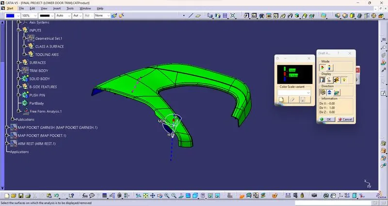
- Before starting the draft analysis ensure that the ‘Materials’ option is selected under Customize View Parameters in order to view the results of the analysis.
- Click on Insert >> Analysis >> Feature Draft Analysis.
- Draft analysis window will be opened having three sections - Mode , Display and Direction.
- In the Display section select the compass and drag it onto your component. Place it along the tooling axis.
- Lock the direction of the draft.
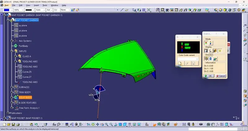
- Another window will be displaying ranges of draft on the component. The ranges are - Green for more than zero , Red for zero and Blue for negative draft value.
- Assign the lower limit as 3 deg to the Green range from the value edition dialogue box.
- Once you do it, click on the component to see the results.
- You can also check the draft value at any point using the ‘Analysis under running point' option in the Display Section.
MINIMUM DRAFT FOR THE COMPONENT = 3 DEG
Lower Substrate:
Map Pocket:
NOTE: The patches shown do not clear in the decided tooling direction. This needs to be modifed by the Class-A Designer. In industry we have to report it to the higher authorities so the component can be modified accordingly.
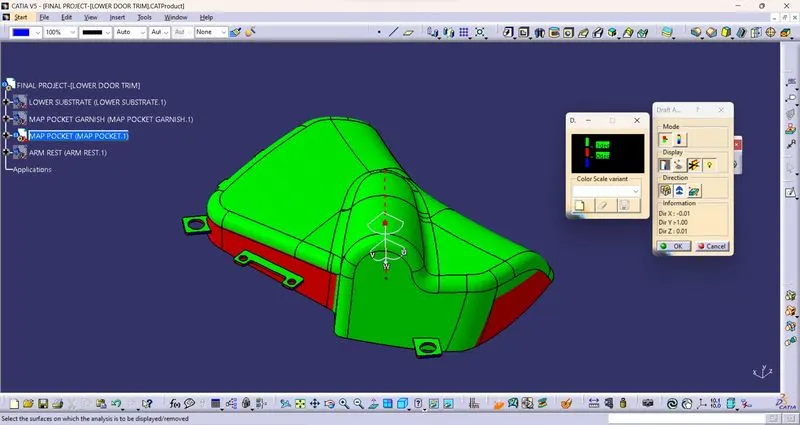
Draft here in the red zone is 3 deg inverse and the blue region is 2.38 deg which needs to be changed. We are neglecting it for the further project proceedings.
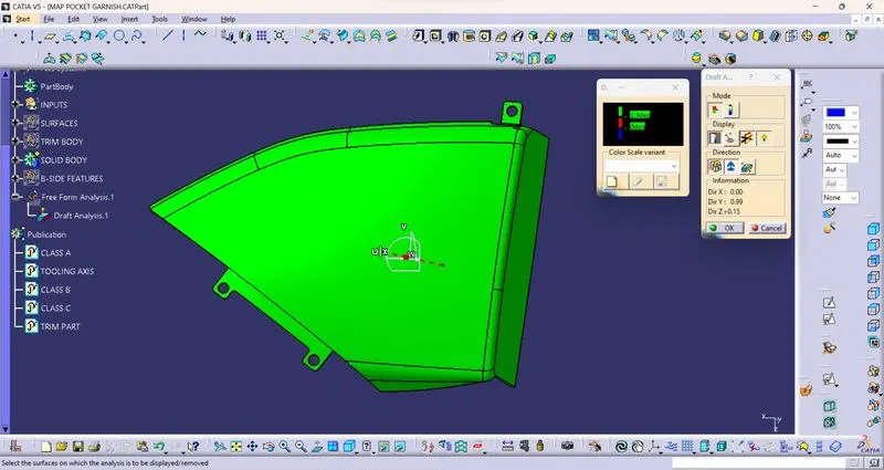
Map Pocket Garnish:
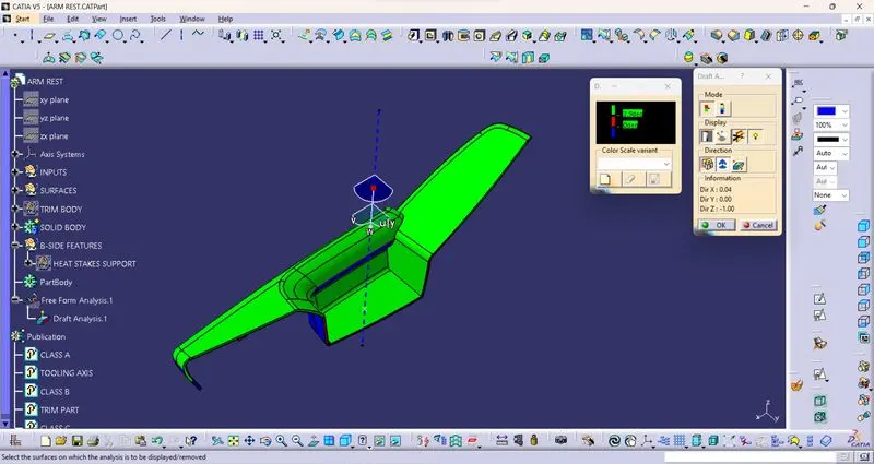
Arm Rest:
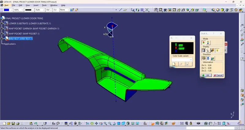
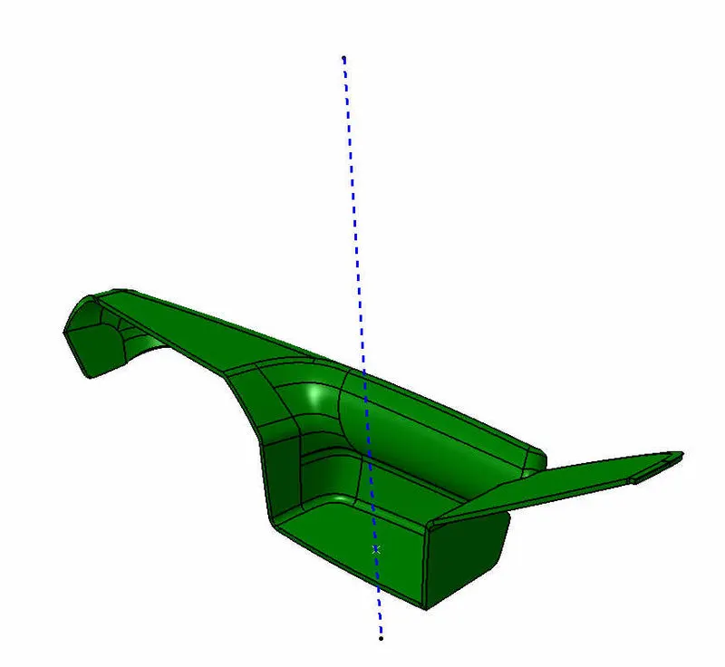
- As we can see in the above images the Car front portion of the arm rest was not clearing in Y- Direction.
- Hence we have used another tooling axis in Z- Direction in order to clear that area.
- Also we have splitted the component in 2 parts for ease of manufacturing.
III] Designing the Solid Component from Class-A:
NOTE: The representation below of the steps mentioned above are for the Lower Substrate only. Similar steps were performed for designing other components
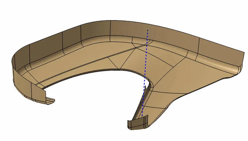
Class-A Surface:
B Surface:
C-Surface:
Closed Surface:
Solid Body Formed:
Lower Substrate:
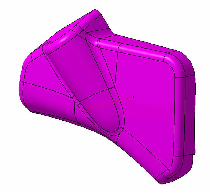
Map Pocket:
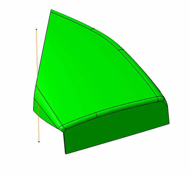
Map Pocket Garnish:
Arm Rest:
IV] Designing the B-Side Features and Flanges:
Heat Stakes: It is the process used to join two or more parts by deformation of the plastic by applied heat and pressure, for a certain time. The applied heat melts the extruded heat stakes on the primary component and it settles on the secondary component. After cooling both the components are firmly joined.
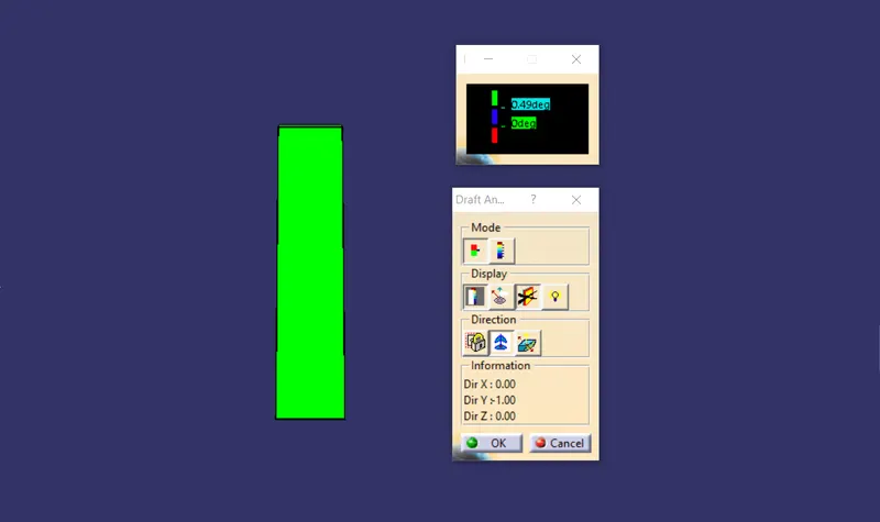
Draft Analysis:
MINIMUM DRAFT = 0.5 DEG
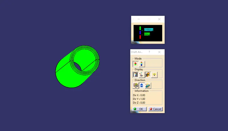
Ribs: Ribs are the features which are used to provide strength and stiffness to the component. Rather than increasing the thickness of the whole component providing ribs reduces cost and also serves as guides for assembly of two components wherever necessary.
Design Rules For Ribs:
- Thickness of the Rib = 0.4 * thickness of the component.
- Rib Root Thickness = + or - 30% of thickness of the component.
- Rib Fillet Radius = 0.25 mm
- Draft = 0.5 deg
- Rib depth < or = 5 * thickness of the component.
- Height / width ratio = 3:1 or 2:1 ( Preferred)
Draft Analysis:
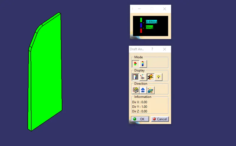
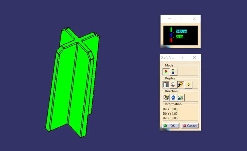
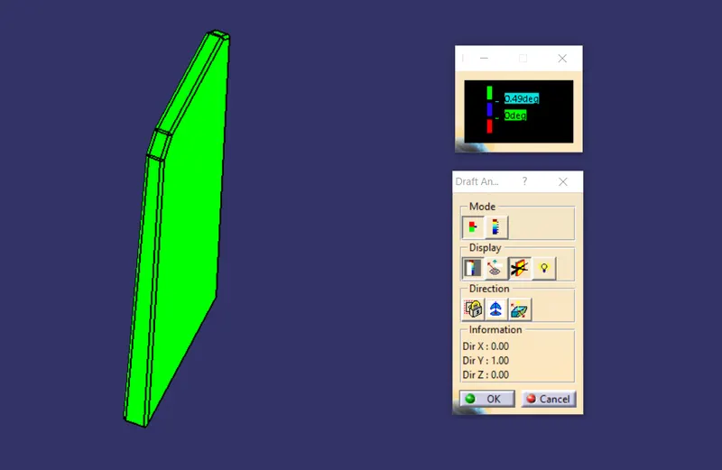
Locators: Locators are the features on the plastic component which enables us to arrest the degrees of freedom of the part and helps in fixation of the component.
The two types of locators used here are:
- 2-Way Locator
- 4-Way Locator
Design Rules For Locators:
- Thickness of the Locator = 0.4*thickness of the component.
- Fillet Radius = 0.25mm
- Draft = 0.5 deg
NOTE: The height of all the locators should be equal.
Draft Analysis:
4-Way Locator
2-Way Locator
Screw Boss: They are designed for assembly of two components using screws.
Design Rules For Screw Boss:
- Outside Diameter = 2 to 2.4 * Diameter of Hole.
- Step distance = 1.5 mm
- Distance of screw Penetrated into the component < or = 0.3 * Thickness of the Component.
Dog House: Many times the screw bosses or push pins need to be given extra length in order to perfectly assemble with other components. We can’t directly increase their height, as all the components are made with proportion to the width and thickness of the component. This can cause sink marks on the component. Hence we provide a dog house wherever necessary and place our engineering feature above it for perfect finish of the component.
Design Rules For Dog House:
- Sink Saver Thickness = 0.4 * Thickness of the Dog House
- Length of Sink Saver = 3 mm to 6 mm
- Upper Width = 12 mm
- Outer Draft = 1.5 deg minimum
- Draft for lifter Axis = 0.5 deg.
Draft Analysis:
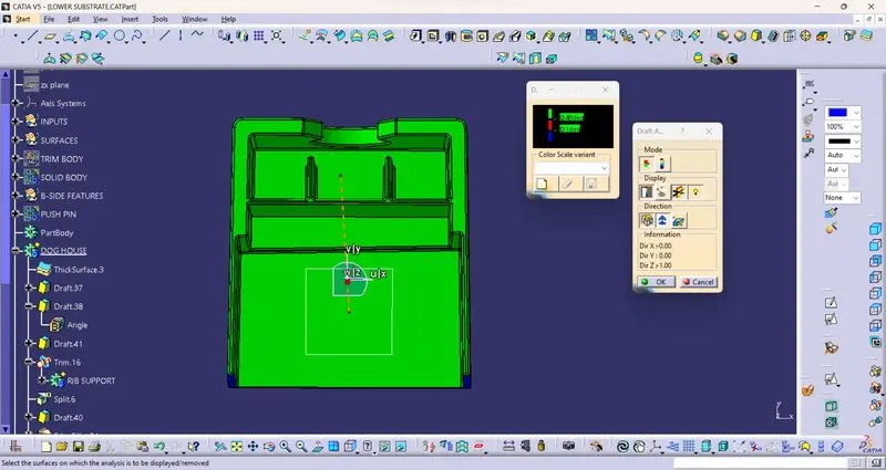
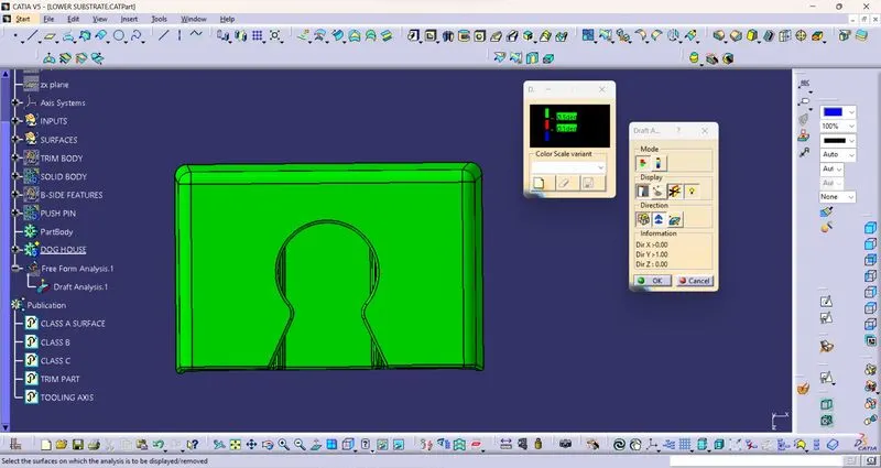
The draft analysis performed above is along the lifter axis, which would clear the inferior area of the don house.
Flanges: Flange is a feature designed for attachment purpose. It has holes in it which helps us mounting one component on the other and carry out the heat staking process.
Draft Analysis:
Lower Substrate:
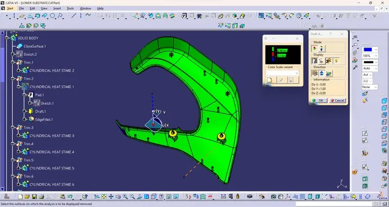
NOTE: The Push pins mounted on the dog house is a standard part used in industries. We haven't followed any design rule for designing them in our project.
Map Pocket:
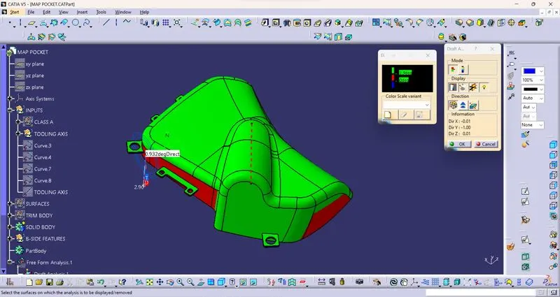
Map Pocket Garnish:
Arm Rest:
Rendering in Catia V5:
The Rendering Tool in Catia helps us to provide the aesthetic look to the component. We can apply material to our model and present our component about how it is going to look. This can be done following the below steps:
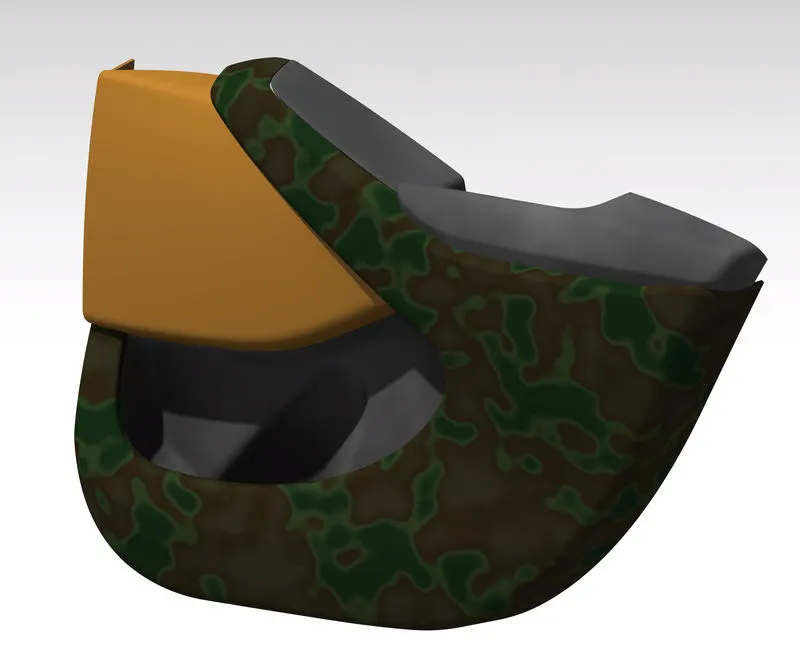
- Click on the " Apply Material " option.
- Select the material which you want.
- Click on the part from the tree structure.
- Click on the "Apply Material" and "Ok".
- Further Click on the "Render" icon and adjust the environment suitable to your component.
- Click on "Save" to save the rendered image of your component.