Week 12- Final project
AIM.
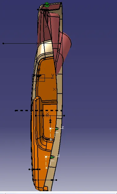
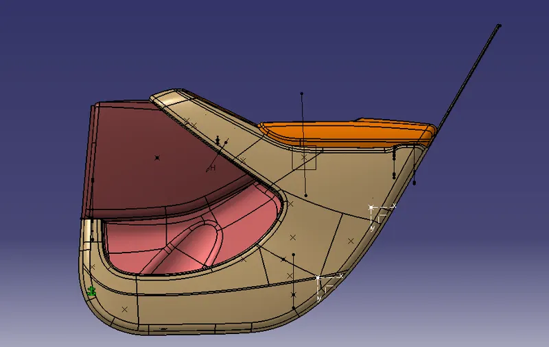
Design of vehicle interior door trim using the given class A surface and create the attachment features as per design rules.
CREATING TOOLING AXIS.
- We have created tooling for all four parts.
- Creating a tooling axis to check whether the component will clear the draft analysis test. Here we created a tooling axis based on:
- Bisecting line method
- Using Master sections of attachment features
- Normal to-face part
- Along axis direction (X, Y, Z)
- First, we create a point on the extracted surface and create a plane on the surface.
- Now we have to create the line using the Point-to-direction method.
- Then draw two lines based on the projection of class A or using the intersection of the point’s method.
- Now Using the Normal to-the-surface method, We have to create the tooling axis.
DRAFT ANALYSIS.
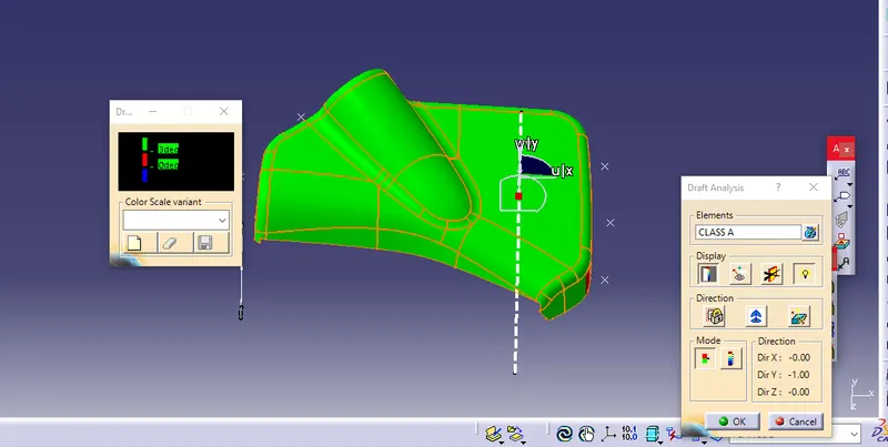
- Draft analysis is important here to check the feasibility of manufacturing the component. A safe draft angle is provided so that the surface of the component upon shrinking does not stick to the core surface. Upon cooling within a few seconds, it is the tendency of the plastic moulded component to shrink towards the core surface. This can cause difficulty to remove the final component or can even damage the surface of the component and core.
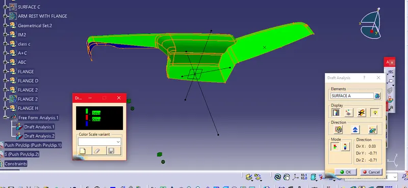
- Here we have to take the draft analysis to check whether the product is manufacturable or not.
- Here all the Surface A cleared the draft analysis test. So it is a manufacturable one.
[BOTTLE HOLDER]
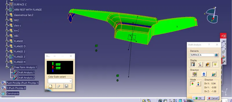
[ARM REST]
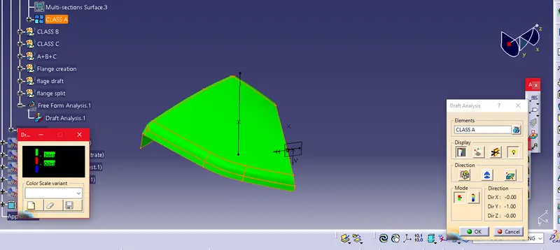
[MAP POCKET]
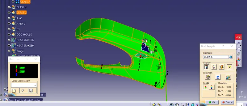
[LOWER SURFACE]
CREATING CLASS B AND CLASS C SURFACES.
- Then I created the Class B surface, Using the following commands.
- Offset.
- Trim.
- Multi-surface.
- Boundary.
- Split.
- Join.
- Untrim.
- Extract.
- Multi-Extract.
- First, I created Class B by offsetting the Class A surface to 2.5 mm because the thickness is 2.5 mm.
- While creating the Class B surface, there were some elements in the surface missing. So we have to patch up or create a new surface on the missing elements using the Sweep command.
- Finally, Class B is created.
Then I created the Class C surface, Using the following commands.
- - Sweep.
- Boundary.
- Smooth- Surface.
- Multi-Extract.
- Here I create the Class C surface with reference to Class A by taking separate boundaries for the edges and smoothing the boundaries to eliminate the vertex in the boundaries.
- Now Using the sweep command, I Sweep the surface to 3 degrees for the purpose of smooth manufacturing. I extrapolate the gap on the sweeping boundaries and Trim it to create the class C Surface.
- Finally, Class C is created.
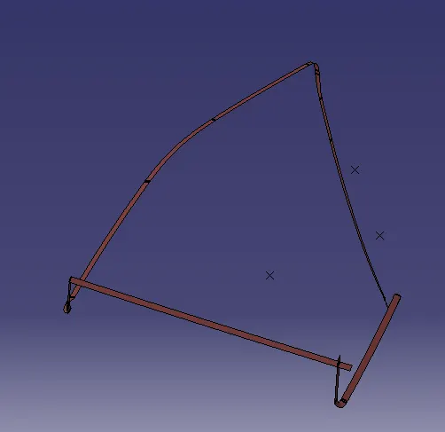
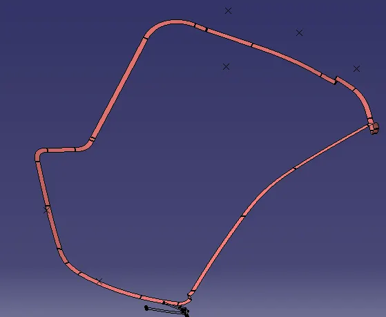
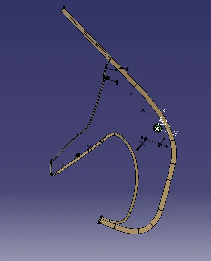
- After creating the Class B and Class C Surface, I Joined the Surface A and Surface C and Trimmed them with Surface B.
Join A+C.
Trim A+C-B.
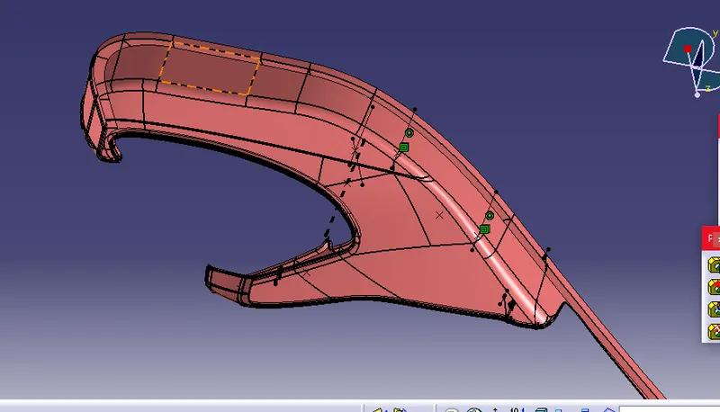
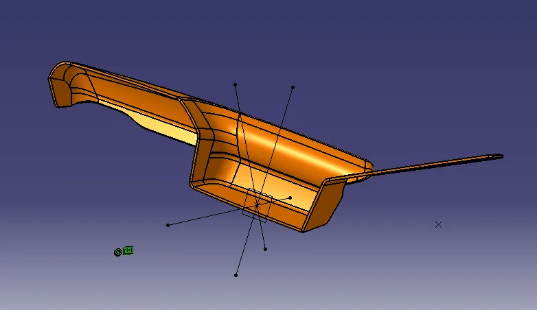
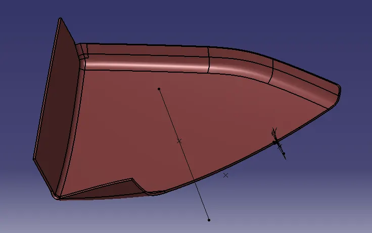
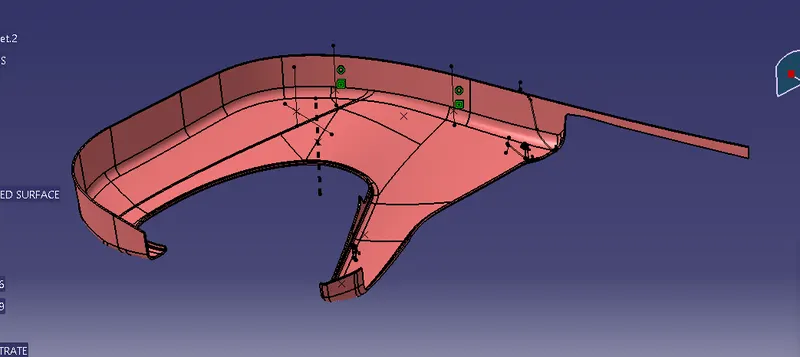
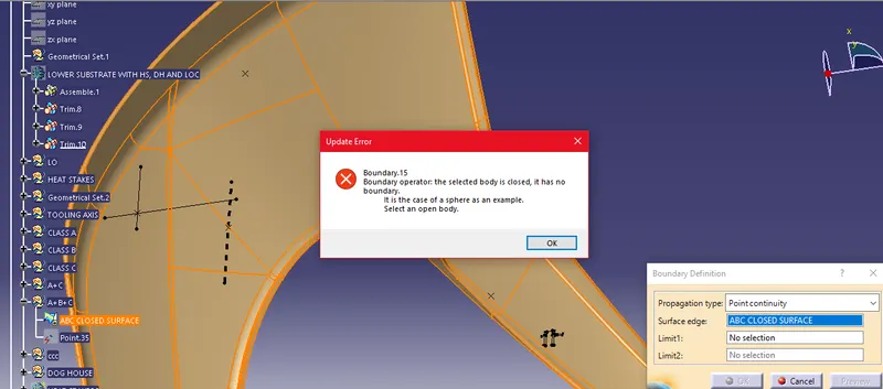
CLOSED BOUNDARY
CREATING FLANGE HEAT STAKES AND DRAFT ANALYSIS.
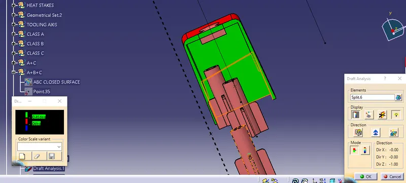
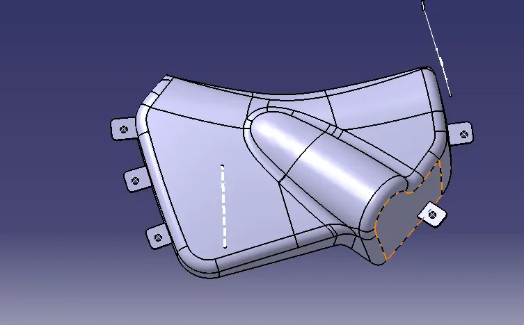
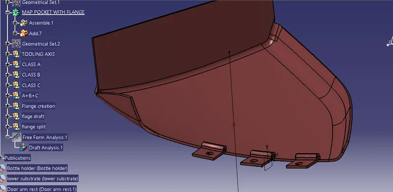
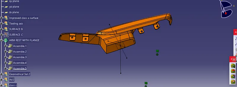
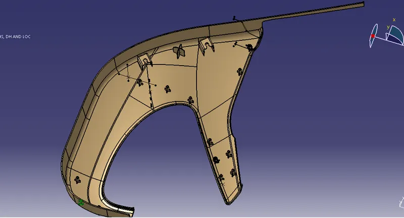
HEAT STAKES, DOG HOUSES AND LOCATORS ARE CREATED AT THE LOWER SUBSTRATE FOR ASSEMBLY WITH OTHER PARTS
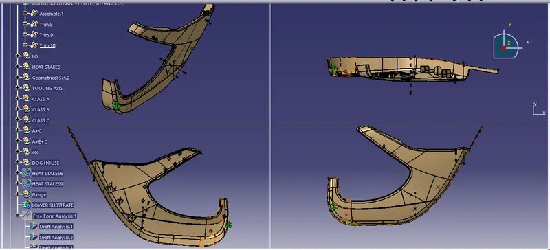
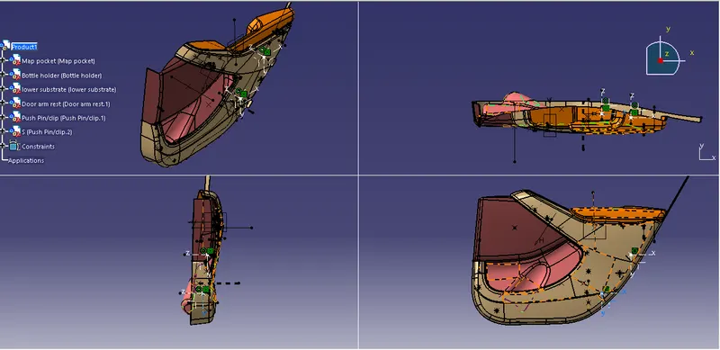
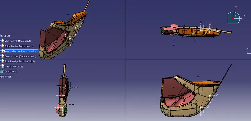
ASSEMBLY OF PARTS
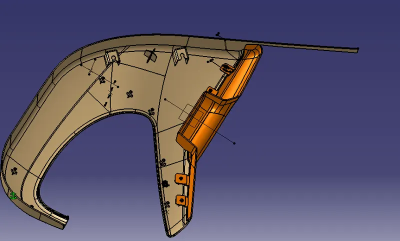
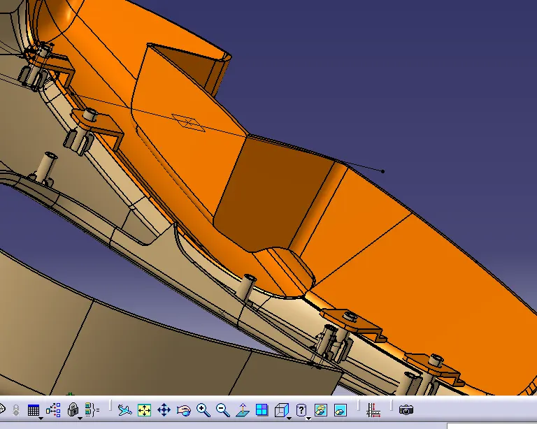
LOWER SURFACE ATTACHMENT WITH THE ARMREST USING THE THE FLANGE AND HEAT STAKES, TO ARREST THE DOF(Degrees of Freedom)
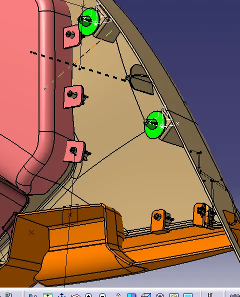
LOWER SURFACE ATTACHMENT WITH THE BOTTLE HOLDER USING THE THE FLANGE AND HEAT STAKES, TO ARREST THE DOF(Degrees of Freedom)
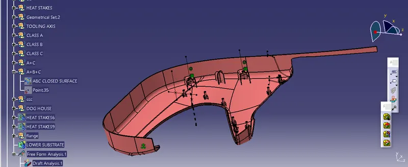
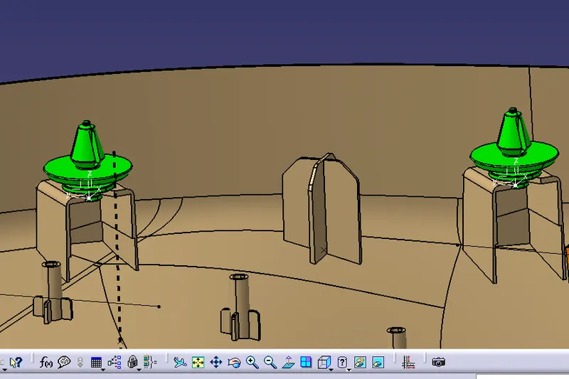
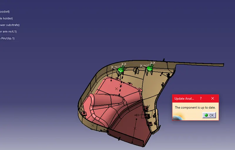
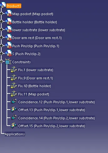
PUSH PIN IS ATTACHED TO THE DOG HOUSE USING CONSTRAINTS
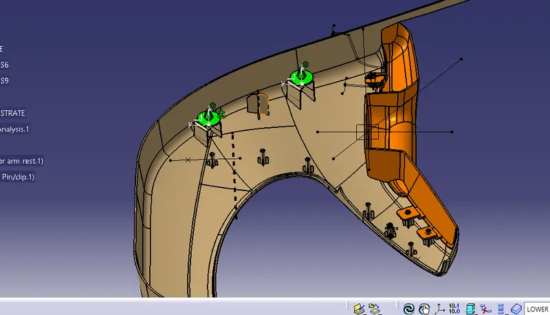
PUSH PIN IS ATTACHED TO THE DOG HOUSE USING CONSTRAINTS
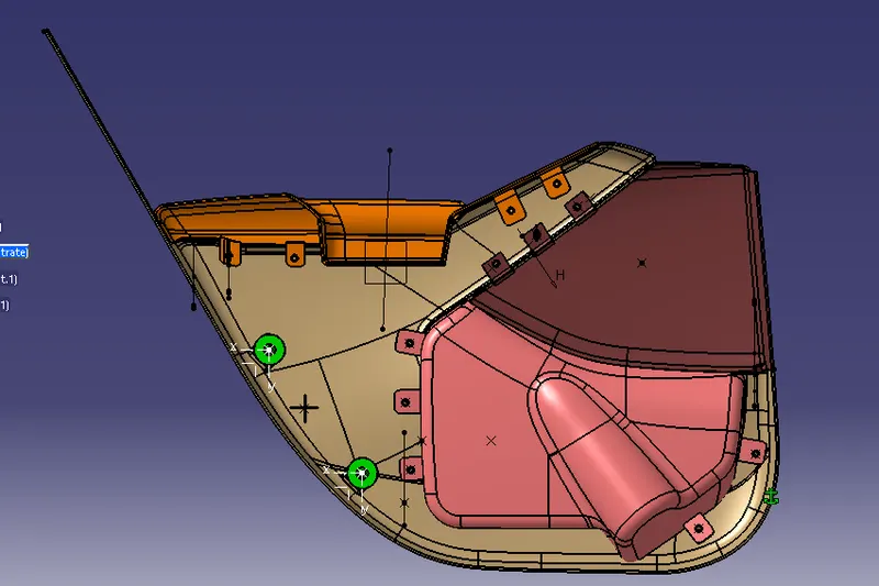
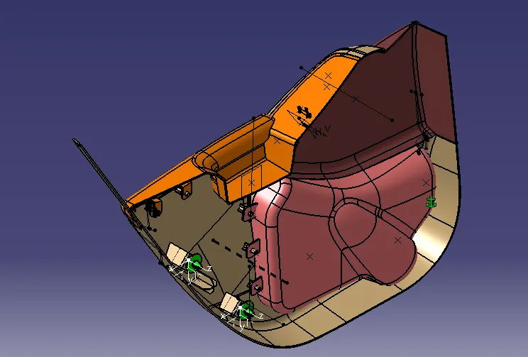
FINAL PRODUCT