Week 12 Challenge
AIM & INTRODUCTION:
To Calculate the Barge Impact load of the Panamax vessel on the bridge shown in figure. The Dead weight tonnage of Panamax vessel is 52500 DWT. The Ship can accommodate maximum of 4500 containers. Each container is of standard 6.1 TEU. It is the heaviest manmade ship maximum load taking ship in the world which carries goods to and fro between eastern & western countries. Speed of the Barge is 60Km/hr.
Given Data:
* Span of the Bridge =12m
* Width of the bridge =7m
* Piers of size 2.5 m x 2.5m
* The Rise of the bridge = 5m
* The Deck slab is 500mm thick
* The cross Girders are 0.75 m x 1.8 m
* Hydrodynamic coefficient(CH)= 1.25.
*W=52500 DWT.
* Speed of the Barge(V) = 60Km/hr.
PROCEDURE:
Calculations;
*Barge Collision Energy, KE=500*CH*W*V^2
where,
Hydrodynamic coefficient(CH)= 1.25.
W=52500 DWT.
V = 60Km/hr.=16.6667m/s
KE=500*1.25*5.2500*(16.667)^2
KE=911822.9531 N-M.
* Barge Damage depth,aB
aB=3100*([1+1.3*10^-7*KE]^0.5-1)
=3100*([1+1.3*10^-7*911822.9531 ]^0.5-1)
Barge Damage depth,aB=178.5881741mm
* Barge collision impact force,PB
For aB≥100mm,pB=6*10^6+1600*aB
=6*10^6+1600*(178.5881741m)
pB=6285741.079N.
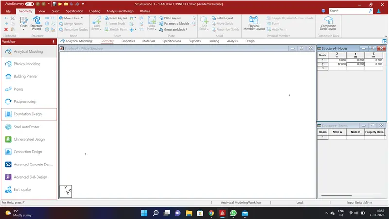
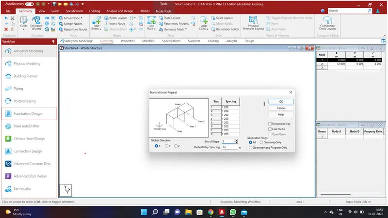
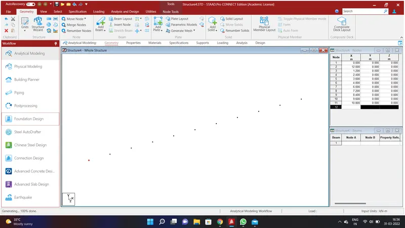
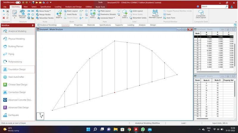
Create a node by assigning the values of Node 1 as X=0;Y=0;Z=0 and Node 2 as X=12;Y=0;Z=0 and click Ok. Select the nodes using node cursor in the select option and go to Geometry Option and go to Translational Repeat in Global X Direction and assigning the values of No. of Steps=9;Default Step Spacing=1.2m and click Ok.
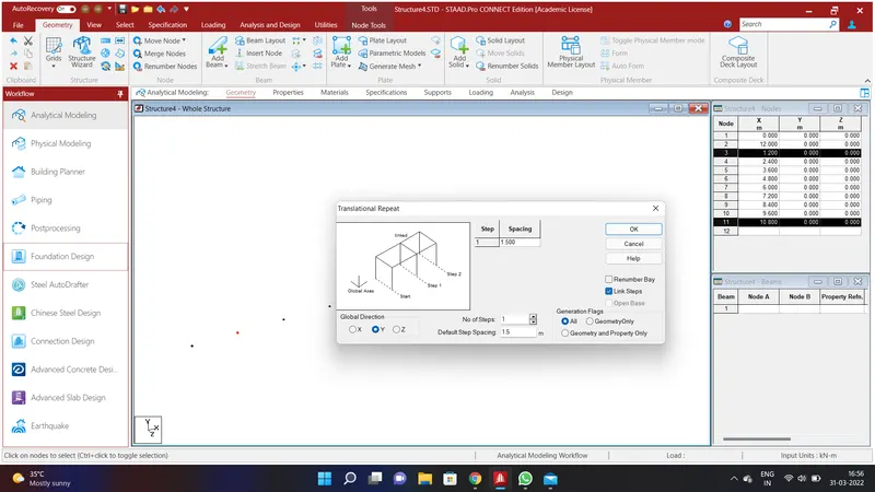
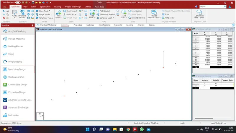
We shall create a arch truss for the bridge. To do that select the 2nd node and 10th node and go to Geometry Option and go to Translational Repeat in Global Y Direction and assigning the values of No. of Steps=1;Default Step Spacing=1m and link steps and click Ok.We shall have created a channel.
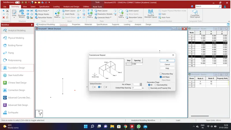
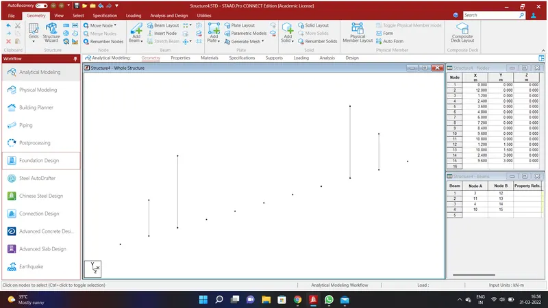
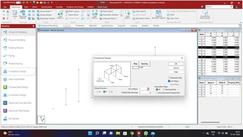
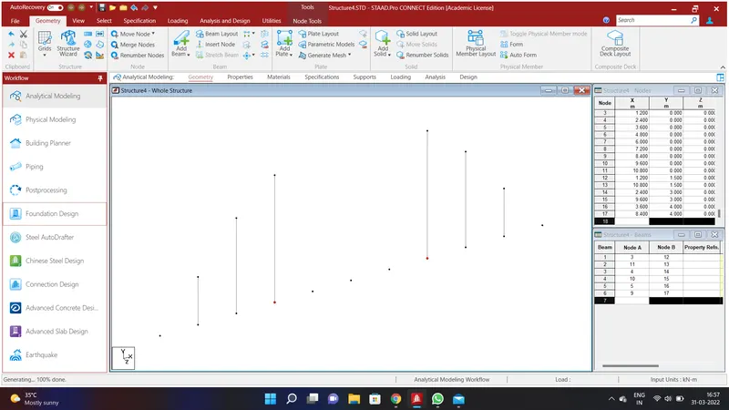
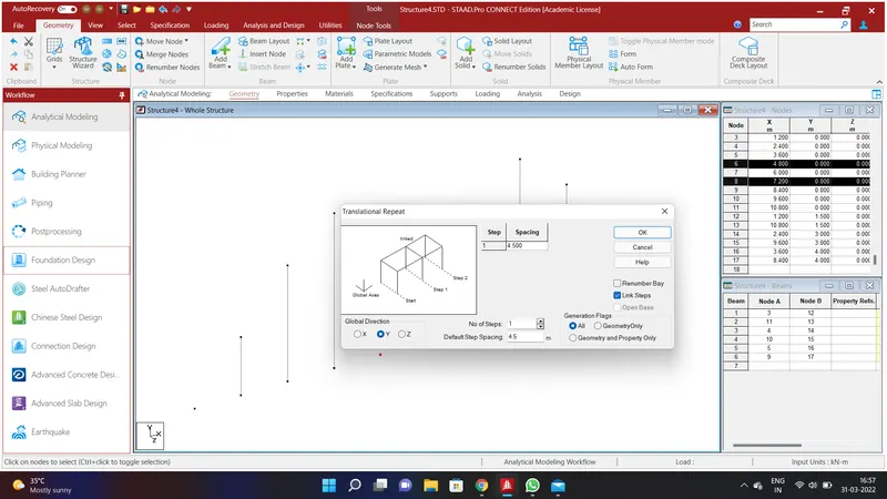
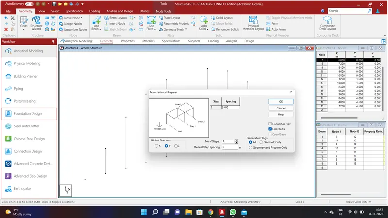
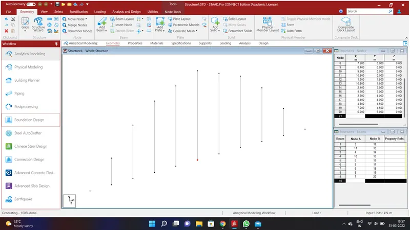
We shall create the truss as shown in thw above problem To do that select the 3rd node and 9th node and go to Geometry Option and go to Translational Repeat in Global Y Direction and assigning the values of No. of Steps=1;Default Step Spacing=3.5m and link steps and click Ok.Again select the 4th node and 8th node and go to Geometry Option and go to Translational Repeat in Global Y Direction and assigning the values of No. of Steps=1;Default Step Spacing=4m and link steps and click Ok.Again select the 5th node and 7th node and go to Geometry Option and go to Translational Repeat in Global Y Direction and assigning the values of No. of Steps=1;Default Step Spacing=4.5m and link steps and click Ok. Again select the 6th node and go to Geometry Option and go to Translational Repeat in Global Y Direction and assigning the values of No. of Steps=1;Default Step Spacing=5m and link steps and click Ok.
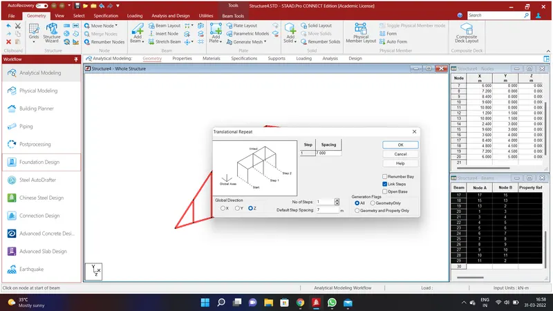
Using Add beam option in the Geometry menu connect all the nodes. After creating the beams select all the beams go to Translational Repeat in Global Z Direction and assigning the values of No. of Steps=1;Default Step Spacing=7m and link steps and click Ok. We wll have created a bridge members.
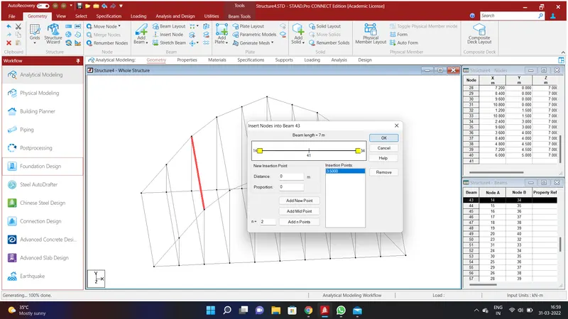
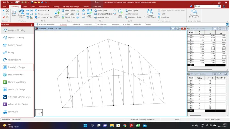
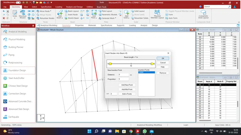
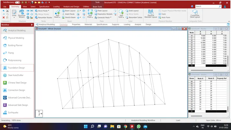
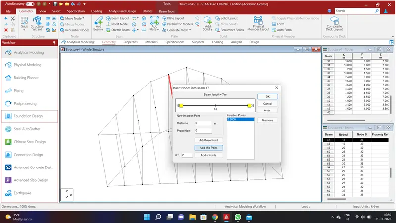
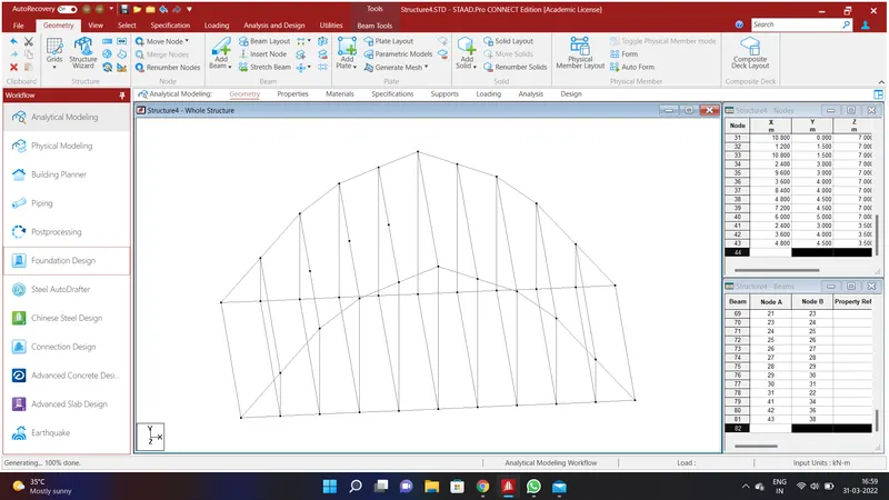
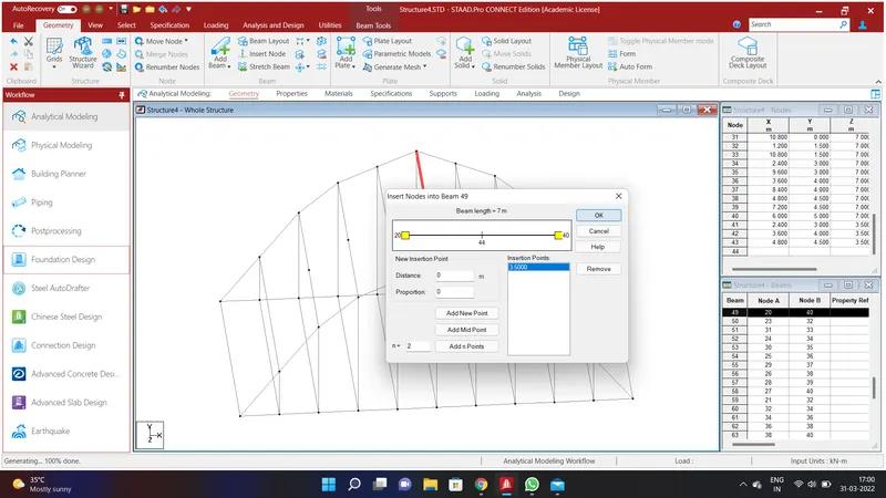
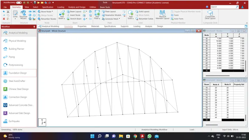
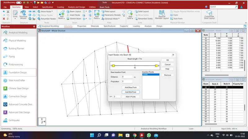
We have to assign angle sections to the top beams. To do that go to Geometry option and select the top beams along Z axis and go to Insert Node and select AddMidPoint and click ok. Do the same to all the beams.
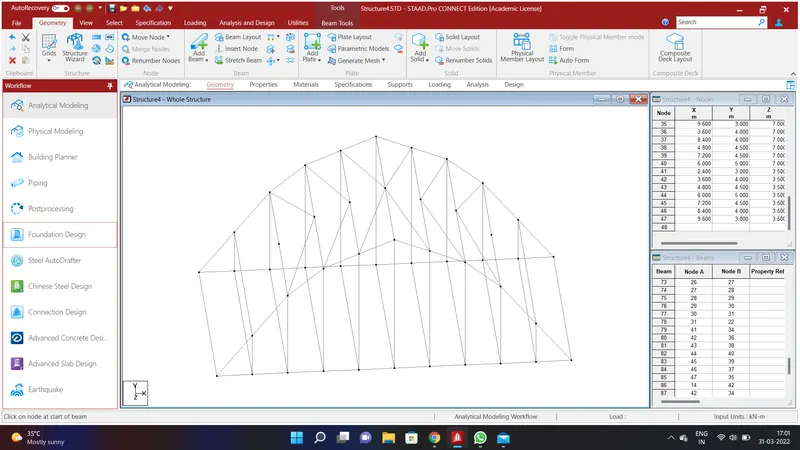
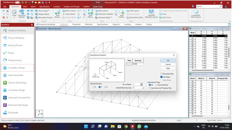
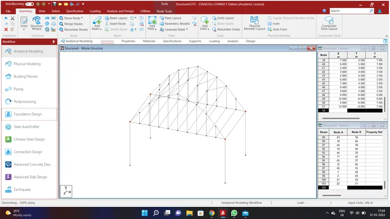
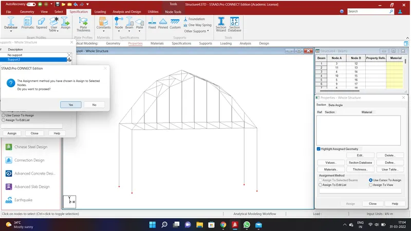
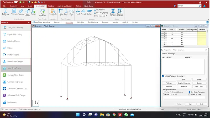
Go to Geometry Option and select Add Beam and connect the top beams as shown in the given problem. We have created top structure of the bridge. We shall assign piers to the bridge. To do that go to Geometry Option and select Translational Repeat in Global Y Direction and assign the values as No.of Steps=1;Default Step Spacing=-6m and click Link Steps and click OK. We shall have created piers for the Bridge. We shall assign fixed support to the piers. To do that go to Specification Option and select Fixed and click Add and select Support 2 and select all the bottom pier nodes and click Assign to Selected Beams and Assign and click YES.
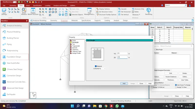
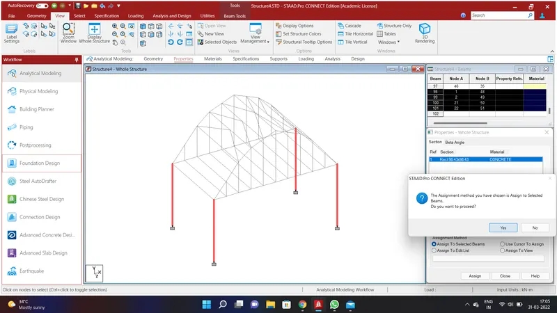
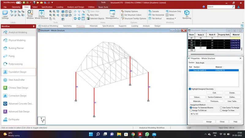
We shall assign properties to the structure. Select all the piers and go to specification Option and select Prismatic Option and go to Rectangle and give the values of YD=2.5m;ZD=2.5m using Concrete Material as mentioned in the above problem and click add. Select the piers and click Assign to Selected Beams and Assign and click YES.
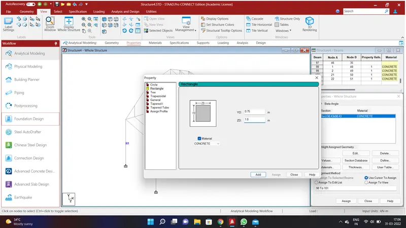
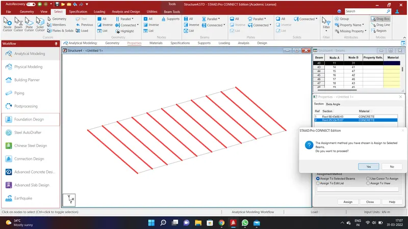
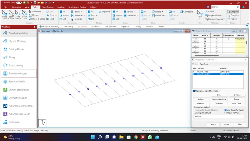
We shall assign Properties to the cross beams . To do that go to specification Option and select Prismatic Option and go to Rectangle and give the values of YD=0.75m;ZD=1.8m using Concrete Material as mentioned in the above problem and click add. Select the cross beams and click Assign to Selected Beams and Assign and click YES. .
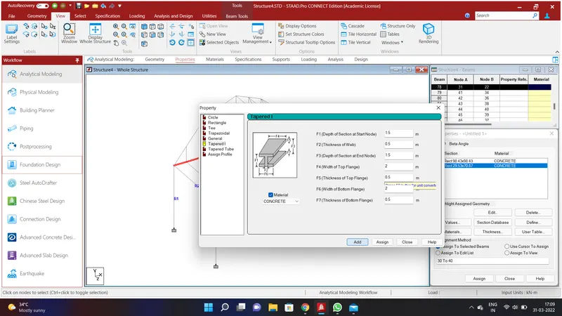
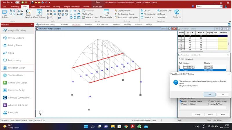
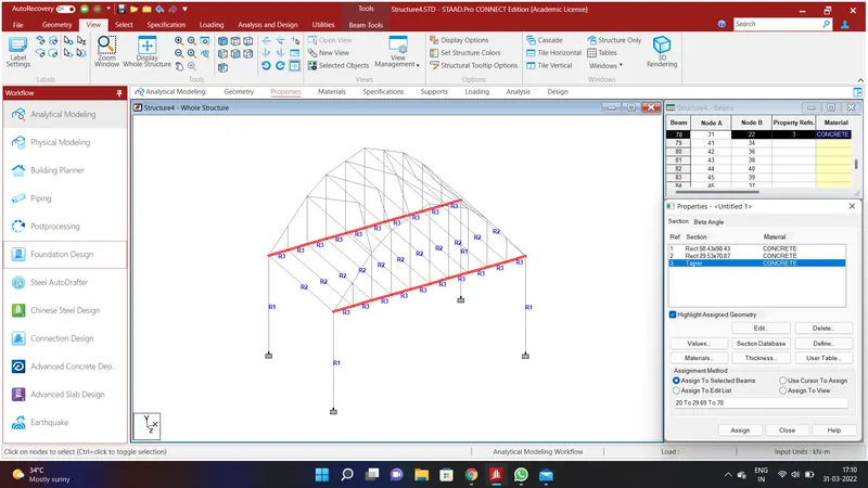
We shall assign Properties to the girders . To do that go to specification Option and select Prismatic Option and go to Tapered I and give the values of F1=1.5m;F2=0.5m;F3=1.5m;F4=2m;F5=0.5m;F6=2m;F7=0.5m using Concrete Material as mentioned in the above problem and click add. Select the girders and click Assign to Selected Beams and Assign and click YES.
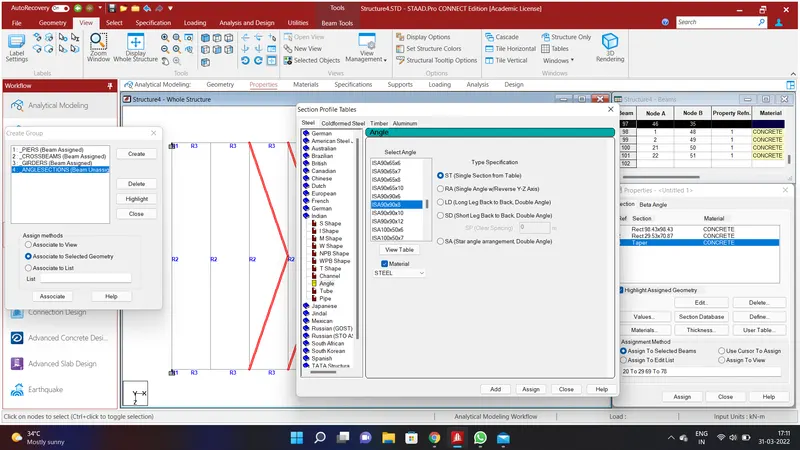
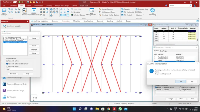
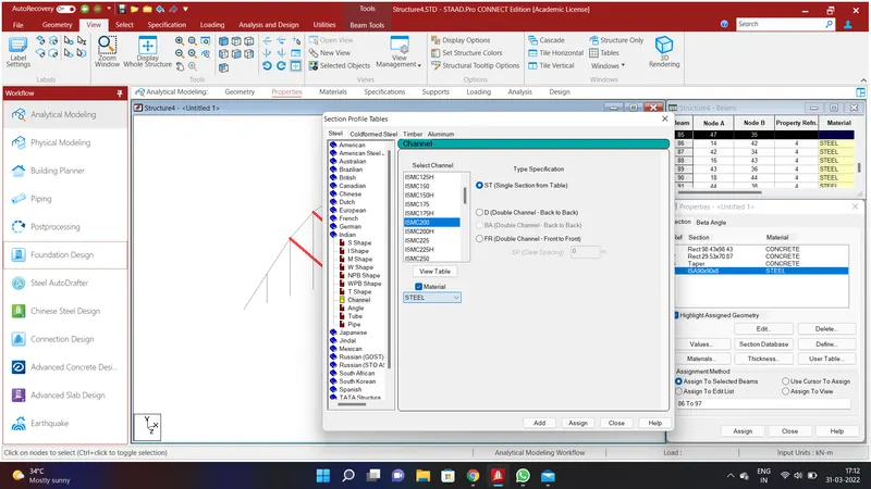
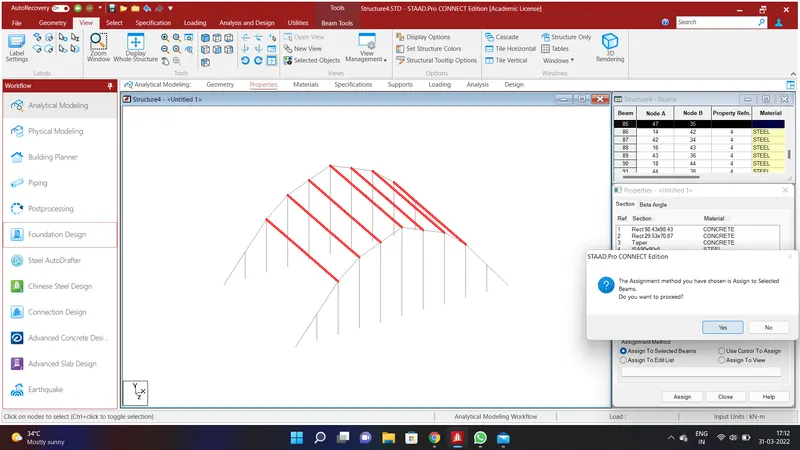
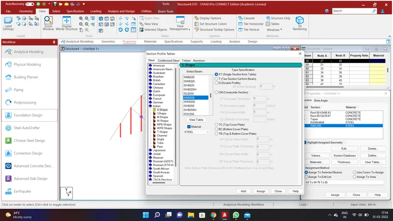
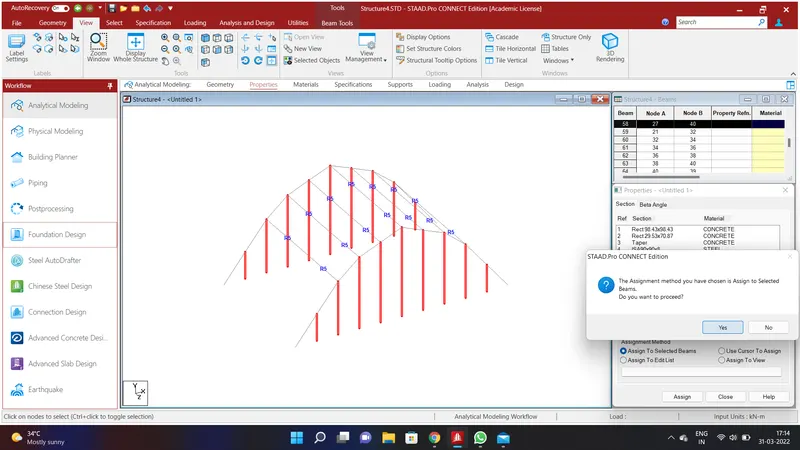
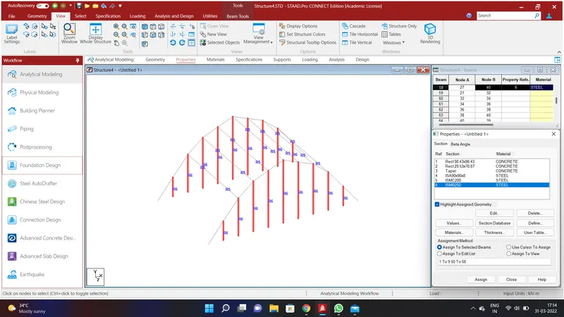
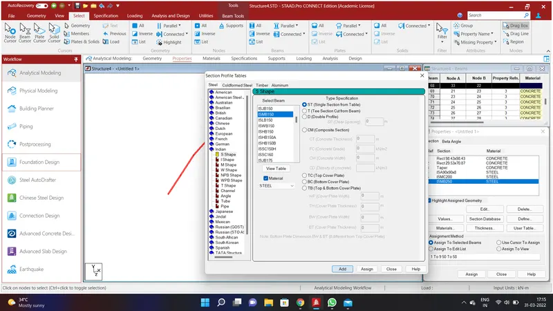
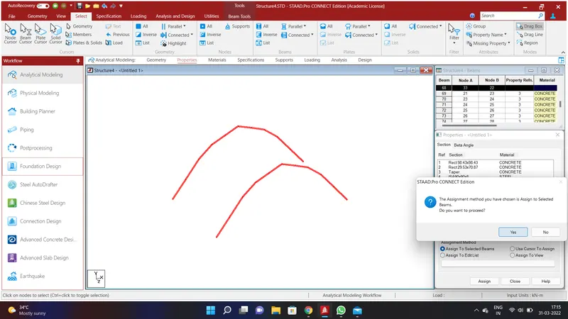
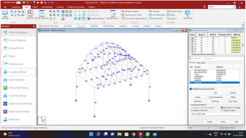
Assign the values to all the channel section as mentioned in the above images.
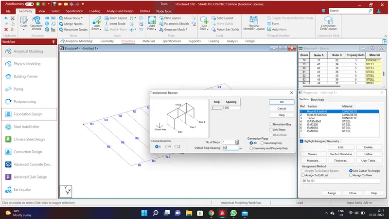
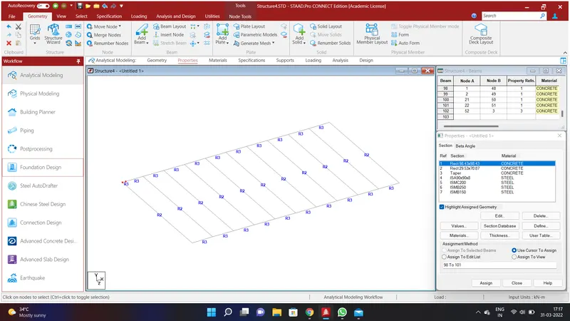
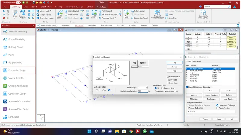
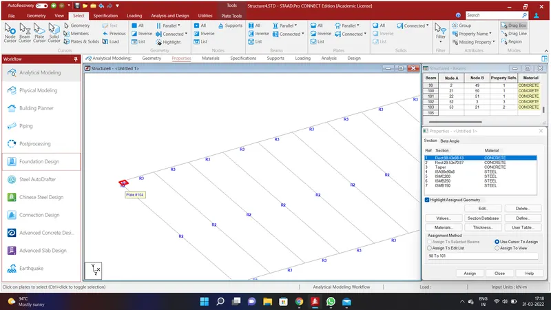
After assigning the values to the structure. We shall create Deck Slab to the bridge. To do that go to Geometry Option and go to Translational Repeat in Global X Direction and assigning the values of No. of Steps=1;Default Step Spacing=0.2m and click Ok. Again select the nodes and go to Geometry Option and go to Translational Repeat in Global Z Direction and assigning the values of No. of Steps=1;Default Step Spacing=0.2m and click Ok. Go to plate cursor in the select option and create a plate.

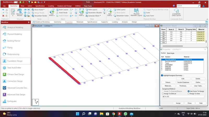
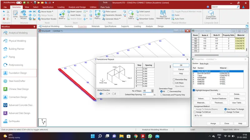
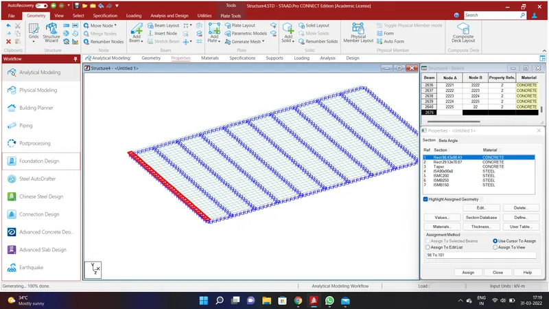
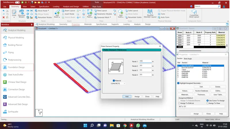
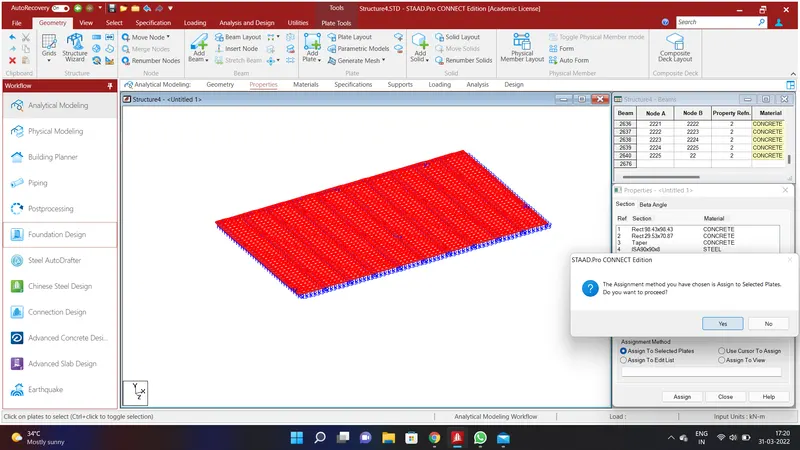
Again select the plate and go to Geometry Option and go to Translational Repeat in Global Z Direction and assigning the values of No. of Steps=34;Default Step Spacing=0.2m and click Ok. Again select the plate and go to Geometry Option and go to Translational Repeat in Global X Direction and assigning the values of No. of Steps=59;Default Step Spacing=0.2m and click Ok. Now we shall assign thickness to the deck slab. To do that go to specification Option and select Plate Thickness and give the values of Node 1=0.5m;Node 2=0.5m;Node 3=0.5m;Node 4=0.5m using Concrete Material as mentioned in the above problem and click add. Select the deck slab and click Assign to Selected Plates and Assign and click YES.
RESULT:
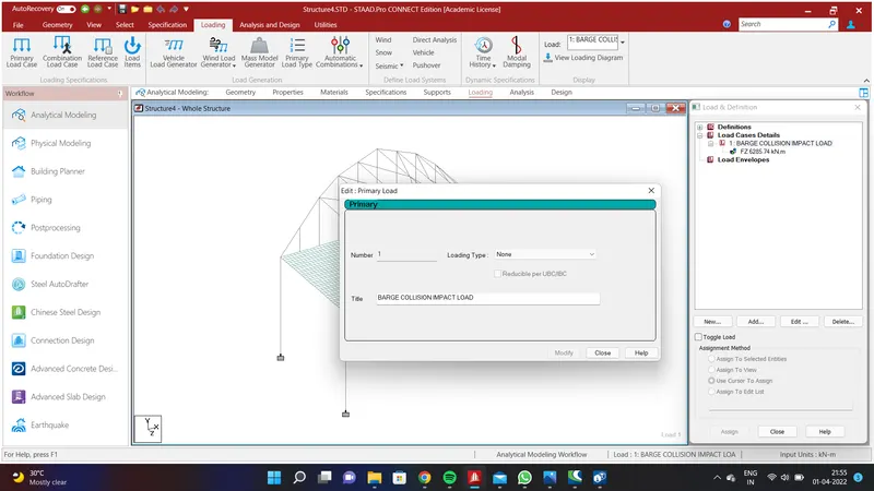
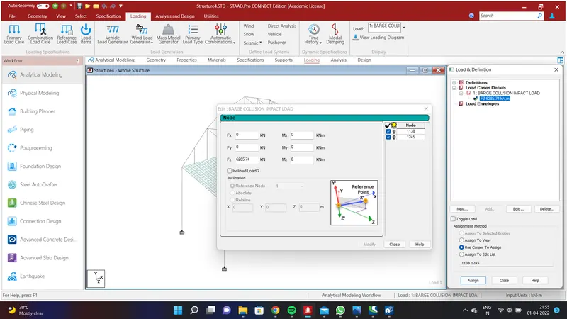
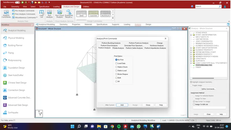
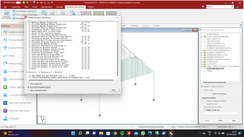
Go to loading menu and select the Load Case Details and click add. Go to Title menu and give the title as Barge Collision Impact Load and click Add. Again select the Barge Collision Impact Load and go to Nodal Load and give the values of FY=0;FY=0;FZ=6285.74KN.m and click Add. Select the node at the centre of the bridge using node cursor in the select option and click Assign to Selected Nodes and Assign and click YES. Then go to Analysis and design and select Analysis Command and Add . Run the Analysis and go to PostProccessing Mode.
REPORT:
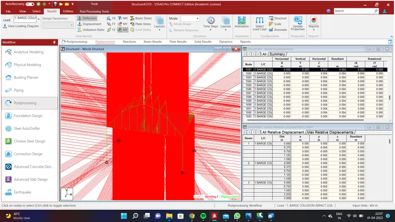
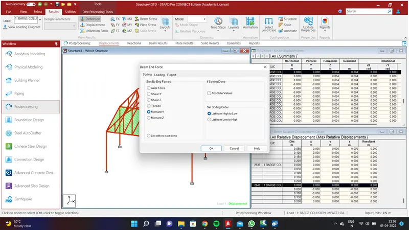
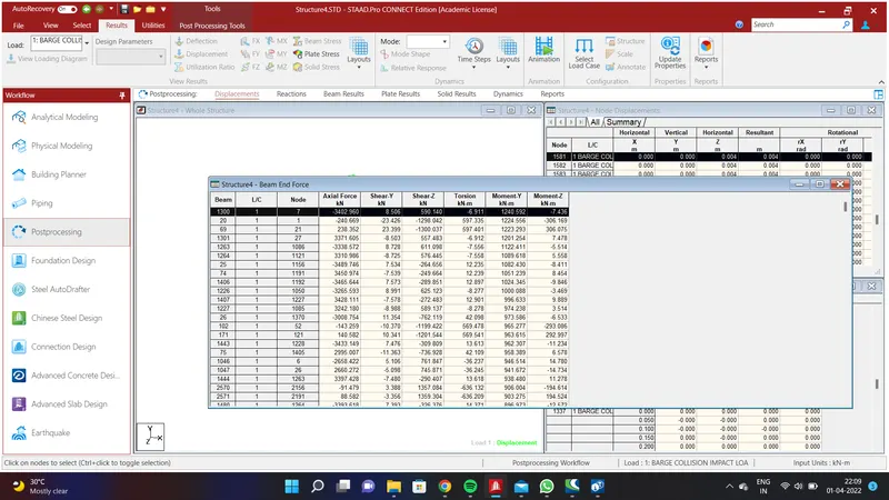
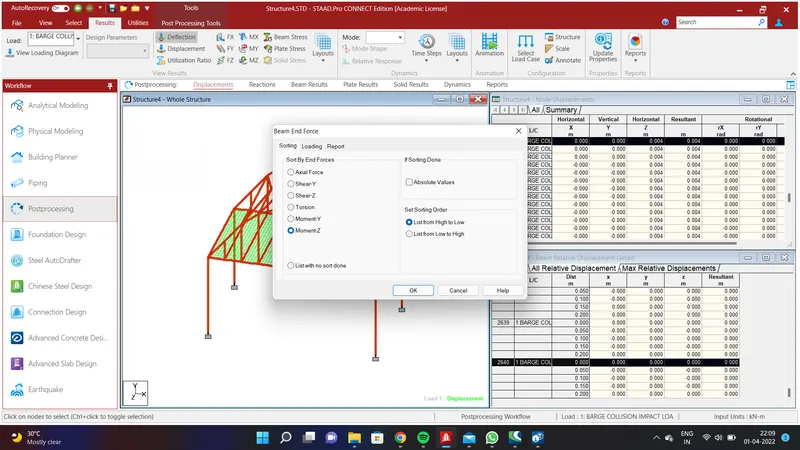
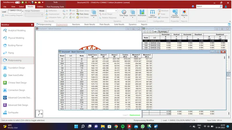
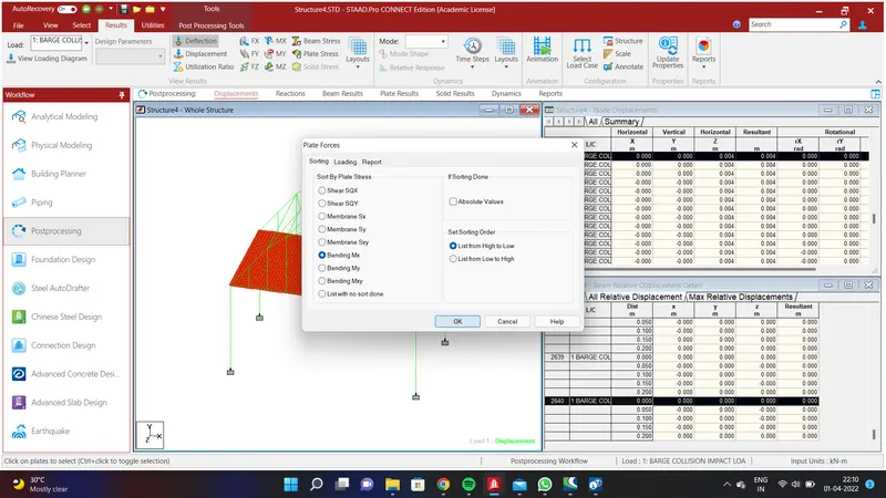
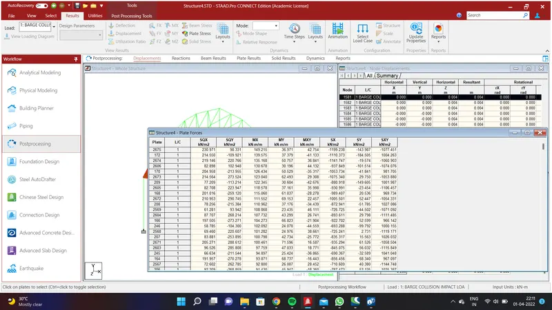
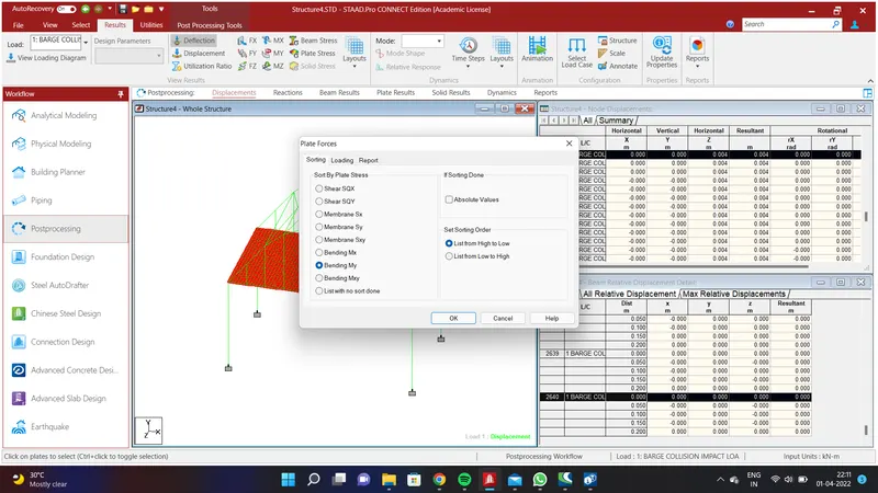
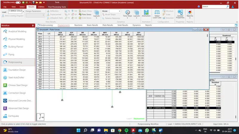
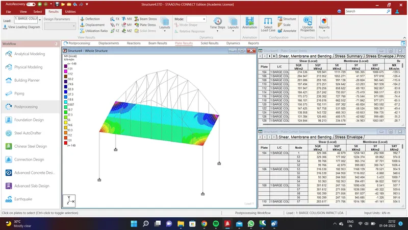
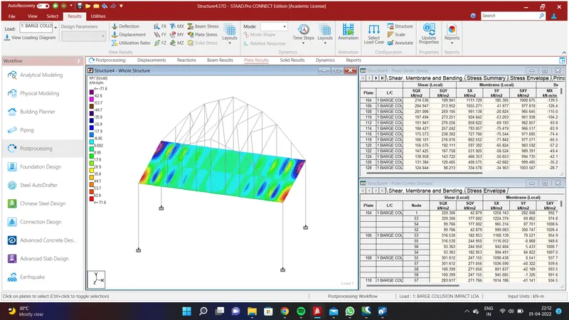
The report is obtained above in the Staad Pro and submitted in the file for the Bending Moment and Shear Force.