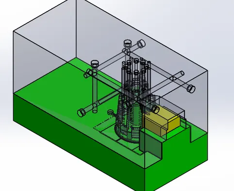
Week 12 Challenge
COMPONENTS:
1.plastic knob
2.CORE PART
3.cavity part
4.inserts
5.slider
These are the components that we are going to built in solidworks .After we finished parts of table fanthen we work on a assembly area .
Let’s discuss about solidworks tools we used
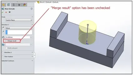
1.extrude boss:
It is most used component in the solidworks it can extrude a sketch along straight line path. After finishing the sketch, use the feature command and go to extrude boss base command. TheProperty Manager for the Extruded Boss allows you to control starting location, extrude depth and draft for the feature, among
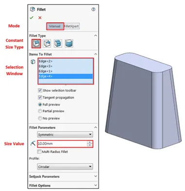
- fillets:
It is used to clear the edges and corners by applyinf and removing some material. It should be noted that fillets of different sizes must be created as separate features. Typically, it is best practice to create the largest fillets first and follow with smaller fillets.
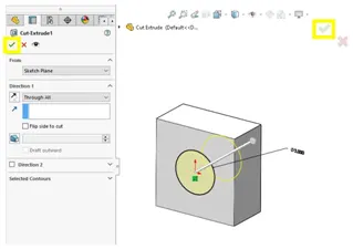
- Extrude Cut:
Similar to the extrude boss feature this feature needs a sketch on the solid body which needs to be cut and the desired shape is then cut off.
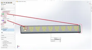
4. Linear Pattern:
It can be used for multiple instances in one or more direction. .Pattern instances inherit the visual properties of the original feature when you select Propagate Visual Properties in the Property Manager
5.Mirror:
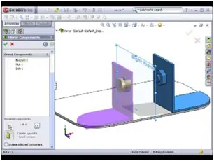
It can be mirrored about a face or plane. : Select a body in a single model or multibody part to create a mirror entity.Multibody parts: Apply features to one or more multibody parts by selecting Geometry Pattern and using Feature Scope to choose which bodies should include the feature.
6.Reference Geometry:
Reference geometry defines the shape or form of a surface or a solid. Reference geometry includes items such as planes, axes, coordinate systems, and points. You can use reference geometry in the creation of several kinds of feature
7.Surface knit
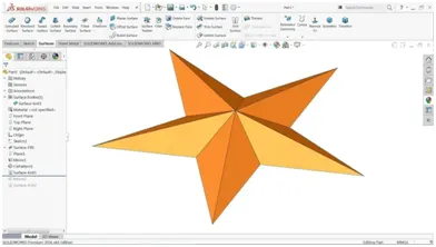
Use the Knit Surface tool to combine two or more faces and surfaces into one. Create a solid body when the knit surfaces form a closed volume, or leave as a surface body. Select Merge entities to merge faces with the same underlying geometry.
8.Surface trim
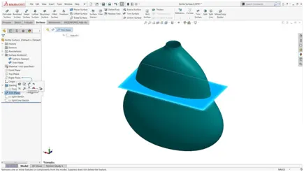
Primarily used to cut away material from a surface, and provides two modes: Standard and Mutual. In Standard mode, a single selection is defined as a Trim Tool, and target surfaces are trimmed accordingly. In Mutual mode, multiple surfaces are trimmed with respect to each other.
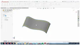
9.Offset surface:
Select surface or faces in the graphics area for surface or faces to offset.
Set a value for offset distance. You can create an offset surface with a distance of zero.
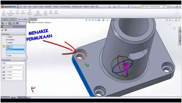
10.Move face:
The Move face command in SOLIDWORKS allows the manipulation of geometry by faces. It is a perfect tool for working with imported geometries.
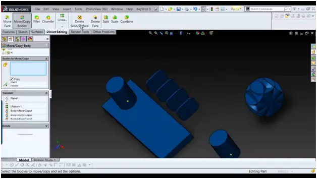
Move/copy:
Specify parameters to move, copy, or rotate bodies. Apply mates between bodies. Click Translate/Rotate or Constraints at the bottom of the PropertyManager (if necessary) to switch to the page you want.
1.plastic knob:
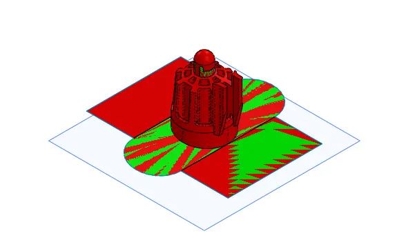
the component will be imported in the part file. here, this component is usedHERE,we are going to mould the plastic knob case. it is differrent from what we discussed in previous model. here we are going to seperate the core and cavity of the model we are going to make the slider of the plastic knob. very firstly, import the given model in the solidworks.scale command is used to avoid the shrinkage of the model.parting line can't be given easily,why because the bottom portion of the cpu fan case not in the straight plane so we have to create the split command to form parting line. after creating the parting line we have to close the holes in model we use shut off surface command in the model.the side wedge shaped in the model should be closed. so we used ruled surface, lofted surface knit surface command to closed the wedge shaped in the model. to create the core and cavity block , the ruled surface command used to extend the surface area.
core block:
after creating the plastic knob is inserted assembly part file .create the seperate part file for core and cavity.just create the rectangle command for the model by using this create blockfor core part
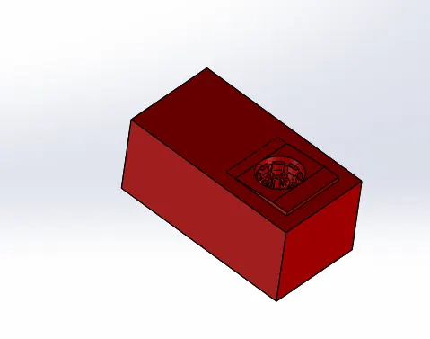
cavity block :
the same procedure is used for the cavity block which is used in the core block
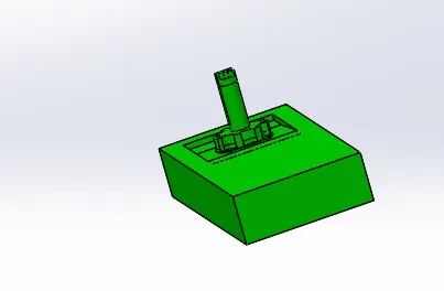
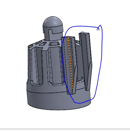
here, we are going to design the slider.
inserts:
Inserts are required place where are possible to obtain the cuts required in the mold block using the tools available. If width of the cut iss too small compared to depth of the cut it might not ossible to create themold tools. The solution is used for this inserts .core block has deeper cut on the outer edge of the model. in this model we need separate imserts .
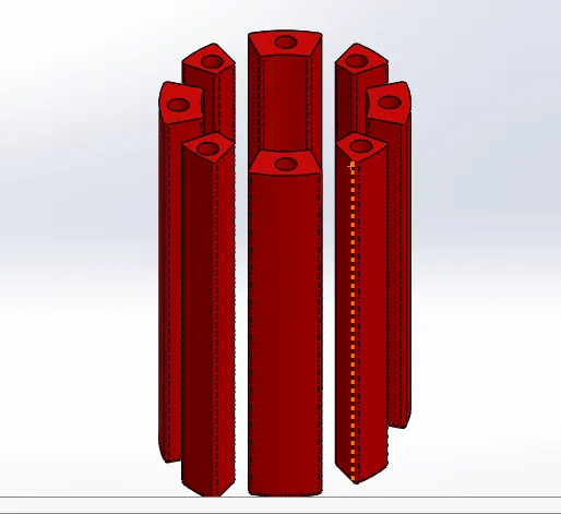
slider:
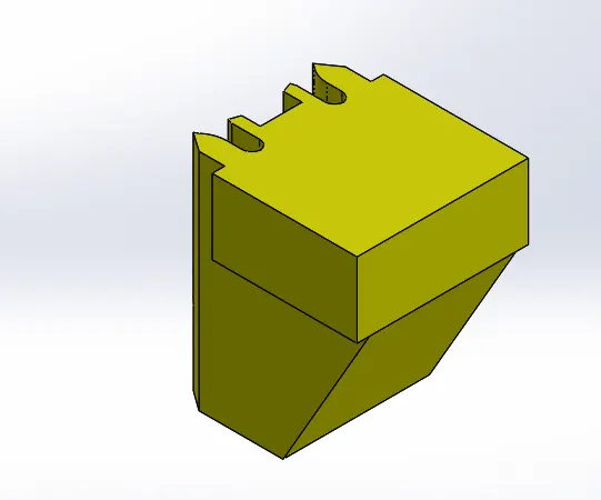
the slider is created based on the core and the cavity block has been made. it is created in the wedge shaped it is created to avoid the undecut while seperating the the core and cavity block . the slider is formed accordin to the undercut provided in the model.
ejector plates:
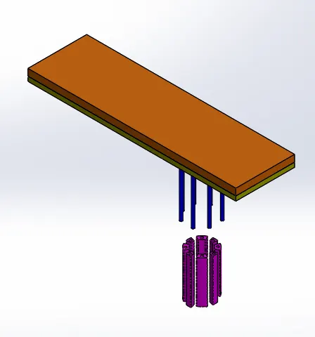
in this backplate and ejector plate is combine together by bolts.backplate is pushed to ejector plate and ejected pins is ejested by the ejected plate and backplate. by the given sketches the ejector plate and ejecter pins are formed. it is created on the core block
gatesand rof runners :
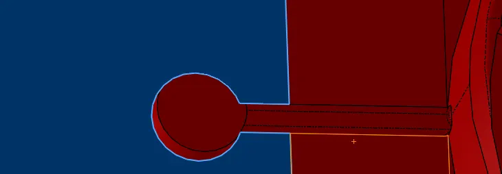
the assembly of channels which facilitate the molten metalto enter into the mould cavity is called the gating system
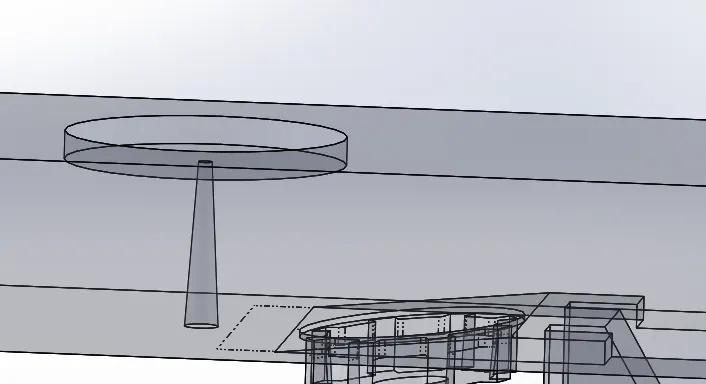
sprue: the sprue is tappered because it may cause air aspiration effects. it is formed between core and cavity.
cooling channel:
it is used to flow the fluids in the proper way it first flow through the first channel and then it flows to the second one and till the sixth channel.