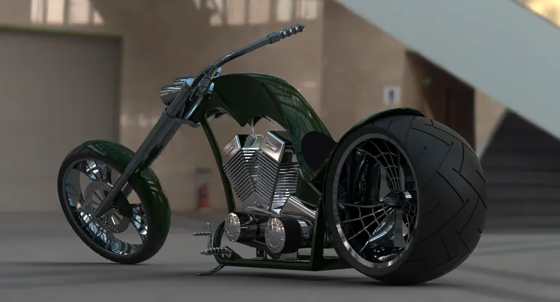
Photo Realistic Rendering
ABOUT SOLIDWORKS:
Dassault Systems solidworks Corp. develops and markets 3D CAD design software, analysis software, and product data management software.
SolidWorks is a solid modeling computer aided design (CAD) and computer aided engineering (CAE) computer program published by dassault system that runs primarily on Microsoft windows. While it is possible to run SolidWorks on an Intel-based Mac with Windows installed, the application's developer recommends against this.SolidWorks does not support
SolidWorks is a solid modeler, and utilizes a parametric system based approach which was initially developed by PTC (Creo/Pro-Engineer) to create models and assemblies. The software is written on parasoild -kernel.
Parameters refer to constraints whose values determine the shape or geometry of the model or assembly. Parameters can be either numeric parameters, such as line lengths or circle diameters, or geometric parameters, such as tangent, parallel, concentric, horizontal or vertical, etc. Numeric parameters can be associated with each other through the use of relations, which allows them to capture design intent.

ABOUT SOLID WORKS VISUALIZE:
SOLIDWORKS Visualize is a photo-realistic rendering tool that utilizes your CAD data to create magazine quality images or commercial quality animations.

By using this software we are going to create modeling of American chopper.
The main components of the chopper are:
1.transmission belt
2.pedal
3.kickstand
4.chain
5.front fender
6.rear fender
7.front wheel
8.rear wheel
9.front fork
10.oil tank
11.engine
12.chassis
These are the components that we are going to built in solidworks .After we finished parts of American chopper then we work on a assembly area after that we render the chopper .To make realistic by using solidworks visualize
Let’s discuss about solidworks tools we used
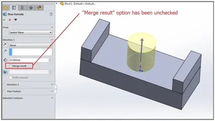
1.extrude boss:
It is most used component in the solidworks it can extrude a sketch along straight line path. After finishing the sketch, use the feature command and go to extrude boss base command. TheProperty Manager for the Extruded Boss allows you to control starting location, extrude depth and draft for the feature, among several other
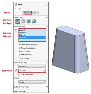
- fillets:
It is used to clear the edges and corners by applyinf and removing some material. It should be noted that fillets of different sizes must be created as separate features. Typically, it is best practice to create the largest fillets first and follow with smaller fillets.
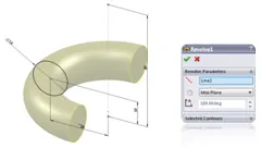
- Revolved Boss Feature:
After finishing the sketch, revolve a sketch around an axis. It is very important to draw an axis in the sketch which needs to be revolved.
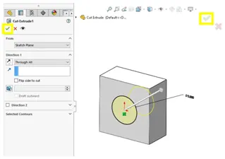
- Extrude Cut:
Similar to the extrude boss feature this feature needs a sketch on the solid body which needs to be cut and the desired shape is then cut off.
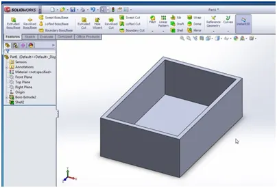
- Shell:
Shell is used to the internal surface and make hollow of the solid body. Using this tool, you can make either completely closed hollowed model or one face opened type.
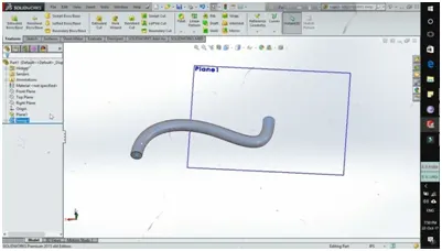
- Sweep Boss / Sweep Cut:
Go to sweep boss in the feature command manger. Select the profile of the sketches and select the option we need. the profile may be open or closed for a surface sweep feature.
- Loft Boss/ Loft Cut:
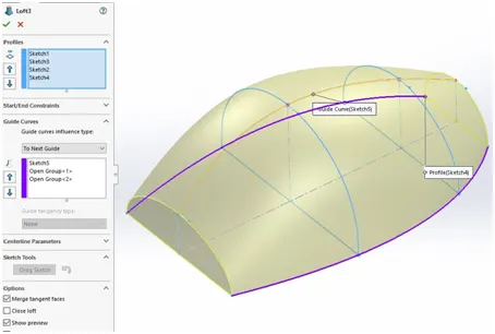
The loft feature creates a shape by making transitions between multiple profiles and guide curves. This tool is very valuable for modelling complex surfaces. You can do some cool stuff when you use this feature properly.
8. Linear Pattern:
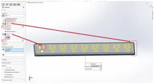
It can be used for multiple instances in one or more direction. .Pattern instances inherit the visual properties of the original feature when you select Propagate Visual Properties in the Property Manager.
- Mirror:
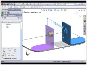
It can be mirrored about a face or plane. : Select a body in a single model or multibody part to create a mirror entity.Multibody parts: Apply features to one or more multibody parts by selecting Geometry Pattern and using Feature Scope to choose which bodies should include the feature.
- Reference Geometry:
Reference geometry defines the shape or form of a surface or a solid. Reference geometry includes items such as planes, axes, coordinate systems, and points. You can use reference geometry in the creation of several kinds of feature
11.Mate :
Mates create geometric relationships between assembly components. As you add mates, you define the allowable directions of linear or rotational motion of the components. You can move a component within its degrees of freedom, visualizing the assembly's behaviour.
12.Projected Curve:
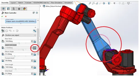
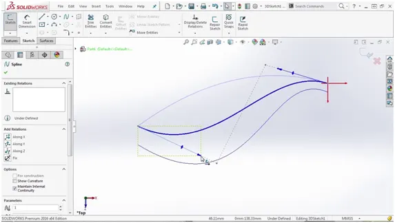
You can project a sketched curve onto a model face to create a 3D curve. You can also create a 3D curve that represents the intersection of two extruded surfaces generated by creating sketches on two intersecting planes. You can create multiple closed or open-contour projected curves from a single sketch. You can also use 3D sketches as input for the Projected Curve tool.
|
Transmission Belt |
|
KICKSTAND |
|
OIL TANK |
|
REAR FENDER |
|
FRONT FENDER |
|
PEDAL |
|
CHAINLINK |
|
CHASSIS |
|
ENGINE |
|
GAS TANK |
|
ASSEMBLY |
|
RENDERING |
|
REAR WHEEL |
|
FRONT WHEEL |
Let’s see how we are going to create American chopper,we are going to discuss part by part as we discussed above.
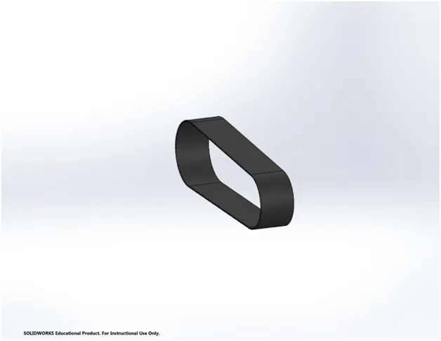
TRANSMISSON BELT:
After sketching in 2D then convert in 3D then it becomes solid body .This solid body is made by single extruded surface .Then two edges has been filleted .The appearances is given here is matte rubber.
KICKSTAND:
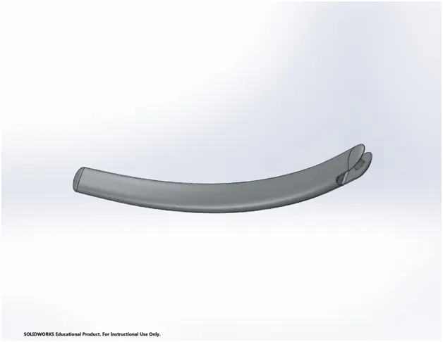
After creating the 2D sketch ,we use a plane for creating a lofted surface and dome tool is used for both the ends .Then we create sketch for cut extrude to flatten the surface which is used for assembly purposes .We use split tool.,An cylindrical boss is created join the cut parts and fillet is applied to the edges of the cuts and joints of the boss The appearances made here is metal chrome.
FRONT FENDER:
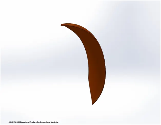
We use axis tool here for a revolve base surface .Creating a sketch for splitting the top surface and bottam surface .Filleted is applied in the both edges .We create a complete front fender. The appearances is siena.
REAR FENDER:
This is similar to a front fender. The same revolve base boss tool is applied .Rear fender has large size than a front fender.Filleted had applied in both the edges. The appearance is siena.
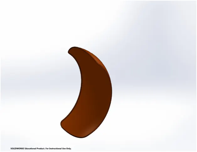
OIL TANK:
Oil tank is sketched by extruded boss bass .It has done two times. Combine tool is used here for the boss extrude. After finishing this shell tool is used to make hollow part and edges are made round by applying fillet. The appearance made here is siena.
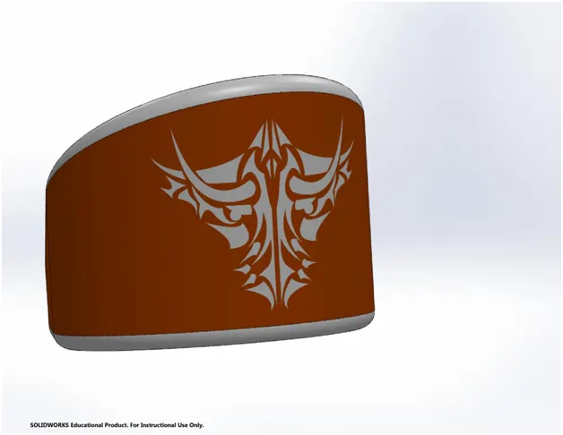
CHAIN LINK:
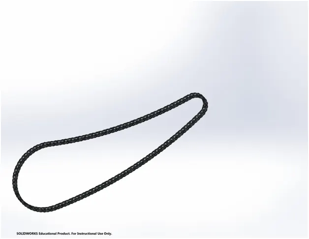
It is quite different from other components .we have to draw the given sketch .Then we make block diagrams and save the block diagram. By using this block diagram frequently use the concentric relation to one joint of the path to another determining the angles filleted is applied and then use circular pattern tool. Then this process is repeated for several times to complete the chain link. The entire loop is completely finally sorting out the arrangements we mirror the face of the links to the pins in the block diagram with respect to mid plane .The appearances is chrome plate. The chain part is connected between rear wheel and engine.
PEDAL:
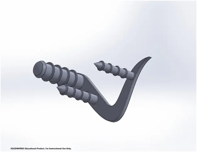
The component ,we are going to create is pedal of American chopper. After sketching the boss extrude tool is created with circular holes for the foot rest. Again the boss extrude is applied with dome tool. The fillets are made to sharp the cuts. The boss extrude is applied in the front part and chamfer is applied twice for surface finish. Circular part is extruded then linear pattern is given filleted is applied. Finally the desired pedal is created. The appearances is chromium plate.
FRONT WHEEL:
After sketching the right plane, revolve bass tool is used with respect to the axis.
Spokes are sketched with the right plane. Rim is created which is merged with hub. Create the spokes with the spline tool and mirror the part. Then create the cut extrude and the circular pattern which is made along the edges. Three forks are made by using the circular pattern. Combine tool is made. Fillet tool is used at the edges. In rotor we create the circle in the middle. Fillet the edges. Create sketch line tool and make circular pattern for 3D dimension. To form, sketch the given dimension and revolve the part by using the temporary axis. Sketch is made in tyre part and cut extrude fillet the edges and make circular pattern.
REAR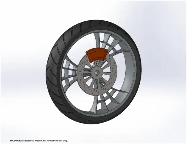 WHEEL:
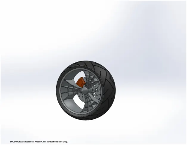
Rear wheel is similar to the front wheel. The main two differences are notified, first one is size of the wheel and the another one is sprocket is created newly in the Rear wheel to connect chain link. Until we are creating caliper is same as we create in the front wheel. Create the sketch and make boss extrude the solid part and again sketch the solid body using circle tool and make cut extrude then filleted edges. By using Circular pattern solid body is created. Chamfer tool for proper shaping.
The appearances for both front and Rear wheel.
Rim - Chromium
Rotor - Chromium
Caliper - Seiana
Sprocket - Chromium
Tyre - Matte Rubber
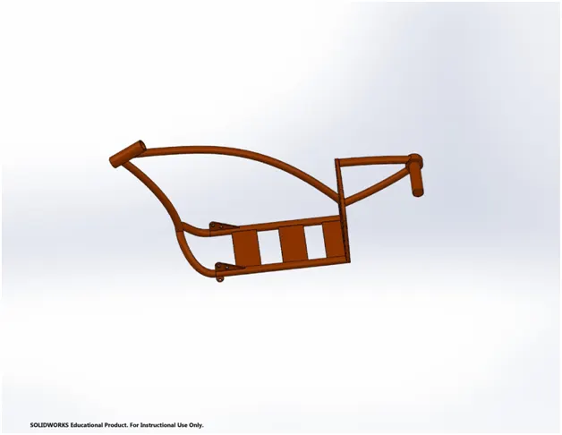
Chassis:-
Take the blue print of the American chopper use the sketch picture tool to take the view two projected curve which is swept along the path and the mirror that portion. Sketch is made and boss extrude the sketched area to attain the desired shape chamfer the block and edges are filleted. Create a new plane and two swept. Then boss extruded the last end dome is created. New plane created and swept top area and split the chassis. The plane is create a bottom area to swept which is made to connect the front fork. To join the chassis with front fork. To join the chassis with front fork a revolve the part is created at the front and joints between the two swept rods is extruded now to make the attachments with the pedals and kickstand. The appearances made is siena.
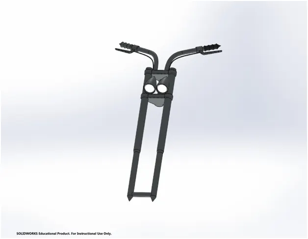
Front fork:
Sketch is created revolve the part and extrude the area and fillet the face and edges. Then make linear pattern. The sketch the front plane and Boss extrude the sketch. Revolve with temporary axis and dome the area, then filleted the edges make solid body move/ copy option. After we focus on the handle which swept using two curve that used to form a projected curve. Handle grips are made using the revolve part and on. The inner face handle bar, we draw geomentry required for the levers and filleted the short edges. Projected curve made to sweep the brake and mirror the portion check visual propogate is on and give combined tool. Appearances is area light, matte rubber and chromium plate.
Engine :
A sketch is made on the front plane and extruded which is the design of the base of motor and several bosses are created along with the same sketch to attain a proper shape next the upper curved part is extruded and all the edges are filleted Now on the rear side of the motor two revolved features are made to make the arrangement for the transmission belt and the spokes are made using the extrude and linear pattern around the circular region and same process is used on the other side of the extrude too. The front of the cylindrical extrude is then cut out with the desired shape The back of the motor the engine case and the top of the case is sketched and extruded one after the other and merged with the entire body a part from the engine body is cut out to make the fin which is linearly patterned throughout the surface as shown in the fig. and the fillets and chamfer are used . Now at the top a sketch is made and the spark plug is created with that the shape of the engine is now mirrored for the twin cylinder .Then the front gear is made for the chain link using extrude and cutting the edges of the 3D circular extrude as the design demands, and at the base of the engine hub the four stand are made for the assembly purposes a link is then swept between both the engines. Now comes the designing of the exhaust pipe from the engine to do that two projected curve is made both the curves are then joined together to form a composite curve which is swept the way from the starting face of the engine to the back according to the dimensions the same process is carried out for the second pipe and at last the wires are attached to the spark plug with two different sweeps. The total appearance given to the engine is chrome plate metal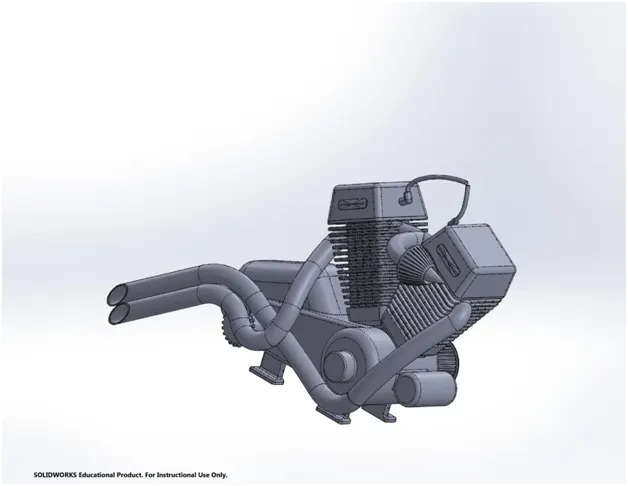
ASSEMBLY:
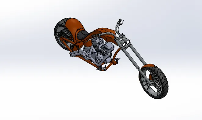
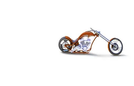
First bring the chassis part , second one is engine then base stand of the engine coincident with the base of chassis mate option is applied. The pedal is brought out ,pins of pedal which are mated with the hole in the chassis. Then coincident mate is formed to make the part fixed, pedal on the another sides of chassis. Then bring the kickstand made some dimension. Mate kickstand with chassis. Transmission belt is mated on the engine drive. Fully defined with mate and coincide with the driver of engine. Next bring the oil tank mated above the engine. Then rear wheel is concentrically mated with the chassis. Parallel mate is applied to fully define the sketch. Rear fenders is applied above the rear wheel. Chain link is brought on to start a width mate between the chain link parts. The sprockets of the rear wheel and gas tank is fixed with distance mate and parallel mate with respect to chassis. The front fork is coincident with upper part of the chassis and then fully defined. Front wheel and front fender is placed like a rear wheel and rear fender. The assembled chopper is attached below,
Rendering:
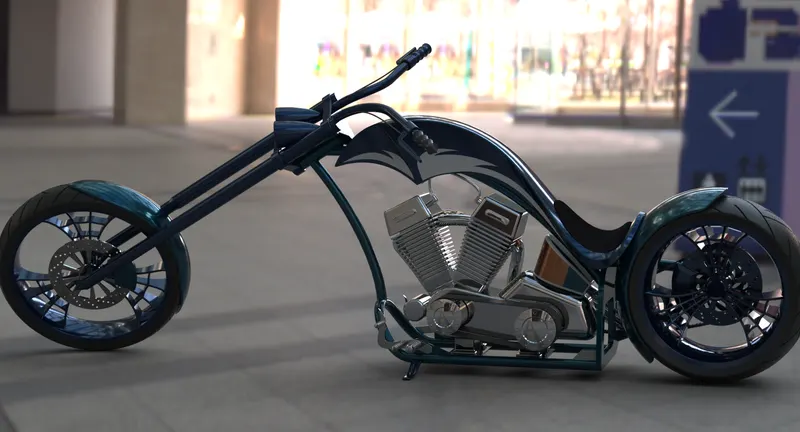
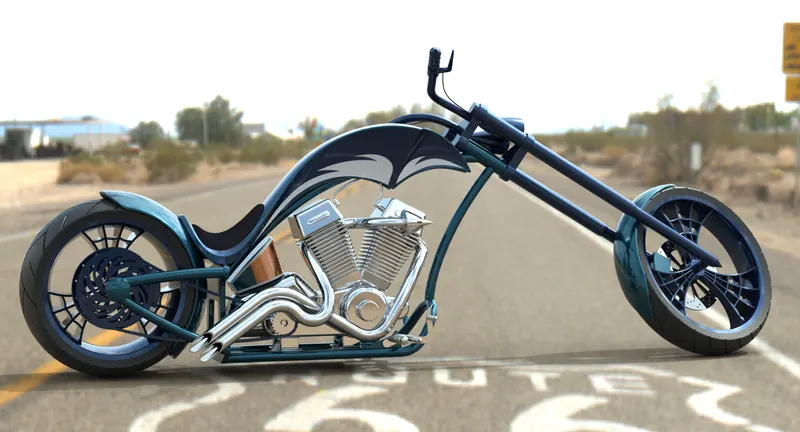
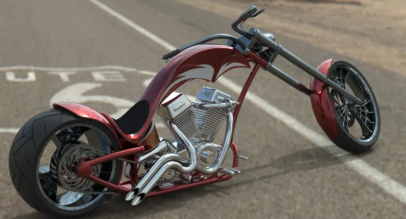
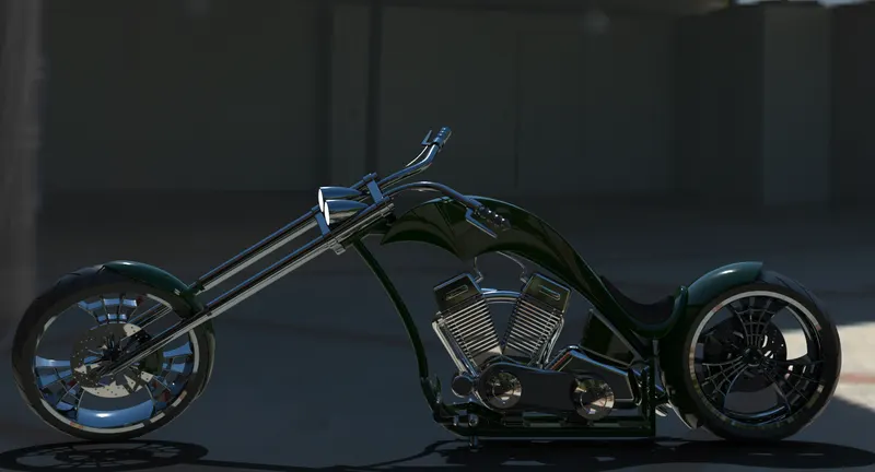
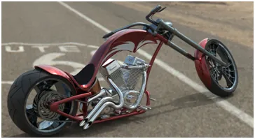
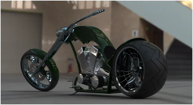
As w discussed above to make more realistic we use rendering. Given decals is applied in the fuel tank,oil tank,rear fender. After that we use solidworks visualize software to make more realistic. We insert the assembly chopper in the solidworks visualize and camera view setting and angle. Take new HDR environment which is applied at back of the chopper. Different appearances can also be given to chopper. Adjusting the brightness, shadow density and gamma levels according to the different requirements of the different backgrounds changing the color of the model. We can give render pass as we wish. Final output is attached below.
rendering images: