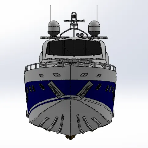
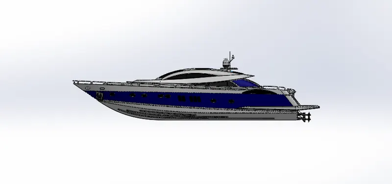
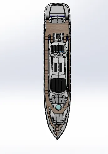
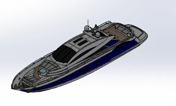
Radar Mast & Final Assembly of Yacht
MODELLING OF YACHT
By using this software we are going to create modeling of yacht.
The main components of the yacht are:
1.propellar
2 . radar
3.hull
4.front seat
5.middle seat
6.rear seat
7.super structure
8.radar mast
These are the components that we are going to built in solidworks .After we finished parts of yacht then we work on a assembly area after that we render the yacht. To make realistic by using solidworks visualize.
Let’s discuss about solidworks tools we used
1.extrude boss:
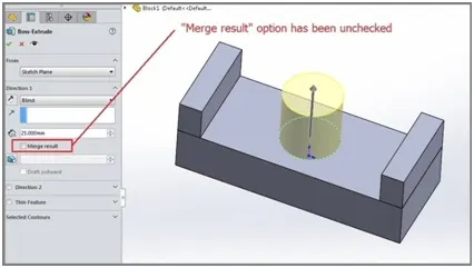
It is most used component in the solidworks it can extrude a sketch along straight line path. After finishing the sketch, use the feature command and go to extrude boss base command. TheProperty Manager for the Extruded Boss allows you to control starting location, extrude depth and draft for the feature, among several other
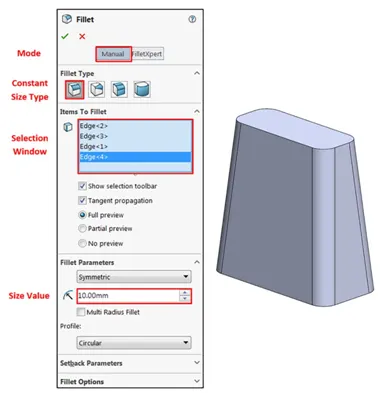
- fillets:
It is used to clear the edges and corners by applyinf and removing some material. It should be noted that fillets of different sizes must be created as separate features. Typically, it is best practice to create the largest fillets first and follow with smaller fillets.
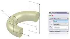
- Revolved Boss Feature:
After finishing the sketch, revolve a sketch around an axis. It is very important to draw an axis in the sketch which needs to be revolved.
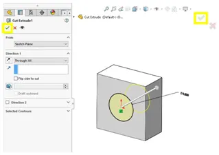
- Extrude Cut:
Similar to the extrude boss feature this feature needs a sketch on the solid body which needs to be cut and the desired shape is then cut off.
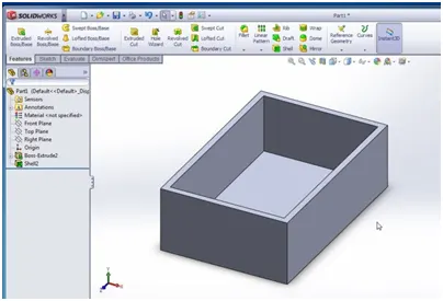
- Shell:
Shell is used to the internal surface and make hollow of the solid body. Using this tool, you can make either completely closed hollowed model or one face opened type.
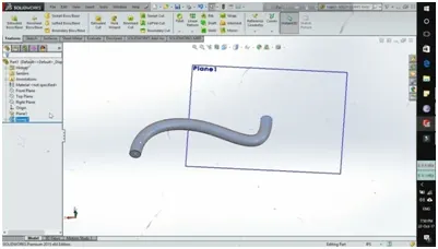
- Sweep Boss / Sweep Cut:
Go to sweep boss in the feature command manger. Select the profile of the sketches and select the option we need. the profile may be open or closed for a surface sweep feature.
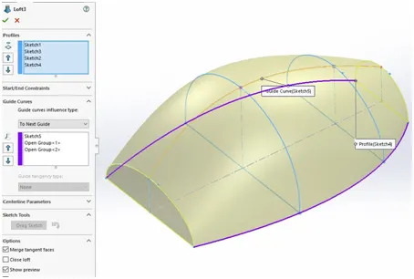
- Loft Boss/ Loft Cut:
The loft feature creates a shape by making transitions between multiple profiles and guide curves. This tool is very valuable for modelling complex surfaces. You can do some cool stuff when you use this feature properly.
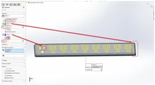
- Linear Pattern:
It can be used for multiple instances in one or more direction. .Pattern instances inherit the visual properties of the original feature when you select Propagate Visual Properties in the Property Manager.
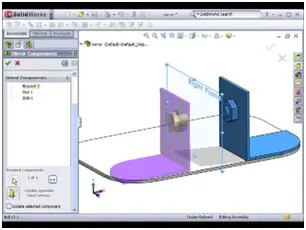
- Mirror:
It can be mirrored about a face or plane. : Select a body in a single model or multibody part to create a mirror entity.Multibody parts: Apply features to one or more multibody parts by selecting Geometry Pattern and using Feature Scope to choose which bodies should include the feature.
- Reference Geometry:
Reference geometry defines the shape or form of a surface or a solid. Reference geometry includes items such as planes, axes, coordinate systems, and points. You can use reference geometry in the creation of several kinds of feature
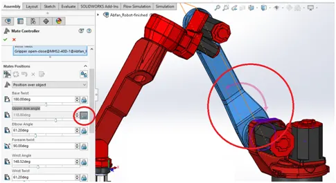
11.Mate :
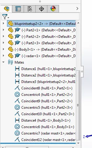
Mates create geometric relationships between assembly components. As you add mates, you define the allowable directions of linear or rotational motion of the components. You can move a component within its degrees of freedom, visualizing the assembly's behaviour.
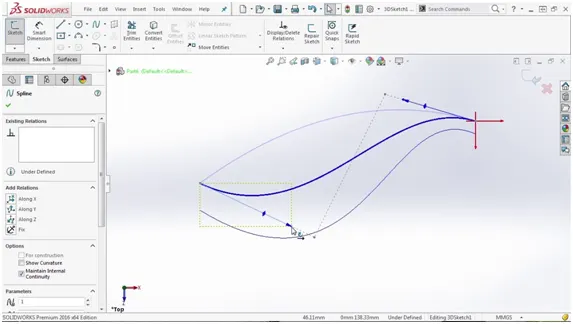
12.Projected Curve:
You can project a sketched curve onto a model face to create a 3D curve. You can also create a 3D curve that represents the intersection of two extruded surfaces generated by creating sketches on two intersecting planes. You can create multiple closed or open-contour projected curves from a single sketch. You can also use 3D sketches as input for the Projected Curve tool.
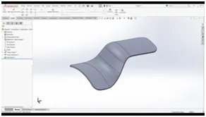
SURFACE EXTRUDE:
Using solidworks surface extrude feature, we can extrude boundary.edges of aface of asolid body or edges in a customized direction. A planar face of a rectangular cube is extruded. Also, a planar
body is used to extrude its boundary edges
.
Surface sweep:
Sweep surfaces are surfaces that are genaerated from a section curve positioned along a path. Parallal sweep is defined as asection curve moving along a guide path while maintaining the section curve to be parallel to a gide path.
Surface knit:
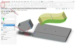
Use the Knit Surface tool to combine two or more faces and surfaces into one. Create a solid body when the knit surfaces form a closed volume, or leave as a surface body. Select Merge entities to merge faces with the same underlying geometry.
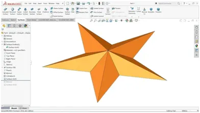
Surface trim:
Primarily used to cut away material from a surface, and provides two modes: Standard and Mutual. In Standard mode, a single selection is defined as a Trim Tool, and target surfaces are trimmed accordingly. In Mutual mode, multiple surfaces are trimmed with respect to each other.
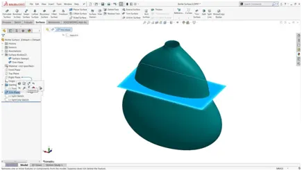
Split line:
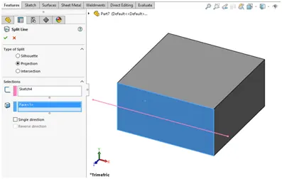
The split line tool isused to an entity on to other surface or curved/planar faces. You are also able to split faces on multiple bodies with one command. Projects a sketch onto a surface. Projection split linescan be pattered.
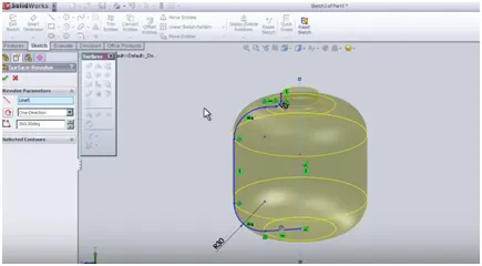
REVOLVED SURFACE:
To create a revolved surface: Sketch a profile and a centerline around which to revolve the profile
LOFTED SURFACE:
It is the simplest way to allow the software to interpolate a shape between two or more profiles. It works with solid and surfaces and it
Has unique functions as well as some overlap with boundary feature.
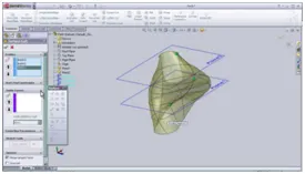
Offset surface:
Select surface or faces in the graphics area for surface or faces to offset.
Set a value for offset distance. You can create an offset surface with a distance of zero.
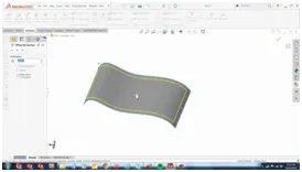
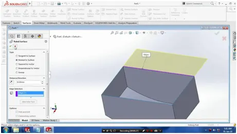
RULED SURFACE:
ruled surface is tangent to the surface that share an edge. Ruled surface is perpendicular to the specified vector. Ruled surface is built by creating a swept surface using selected edges as guide curve.
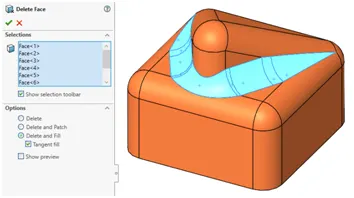
Delete face:
Creates a surface body as once its removes faces,it leavesopen edges in the model.
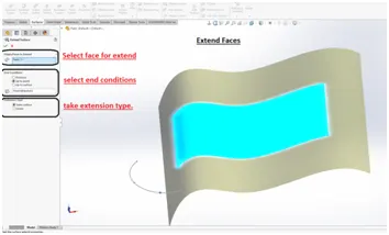
Extend surface:
Extend surface is used to extend the surface which is already created. there are different options avalaible on the extend surface.
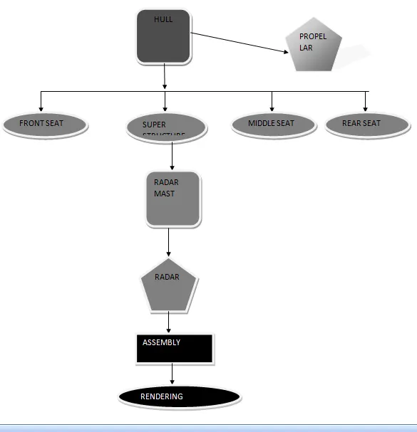
FLOW CHART OF THE YACHT
|
HULL |
|
PROPELLAR |
|
SUPER STRUCTURE |
|
FRONT SEAT |
|
MIDDLE SEAT |
|
REAR SEAT |
|
RADAR MAST |
|
RADAR |
|
ASSEMBLY |
|
RENDERING |
Let’s see how we are going to create the yacht :
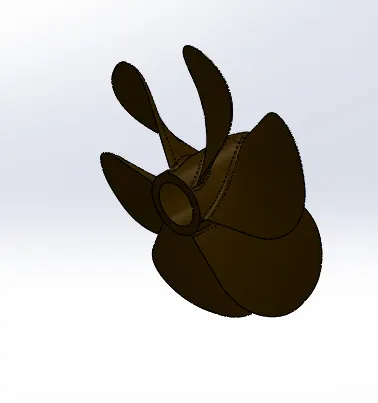
1.Propeller:
After finishing the given sketches, revolve the 2D sketch. Create the new plane and sketch the plane create the lofted surface. Filleted the edges and cut extrude the area and again filleted the edges. The finished surface is given circular pattern.
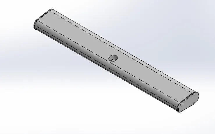
2.RADAR:
The finished sketches are boss extruded and filleted the edges and faces. After finishing the sketch2 boss extruded and filleted the edges.
Sketch pattern is given and again filleted mirror the pattern cut extruded the surface. At last split line is given.
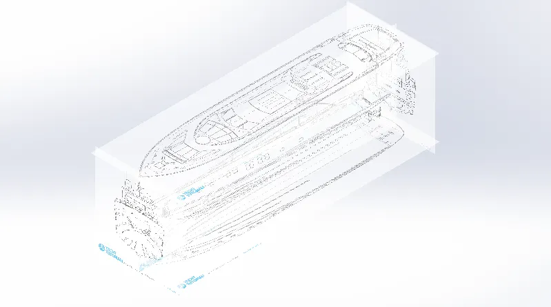
3.BLUE PRINT SETUP:
The front view, side view, back view, top view, bottom view are taken by using the sketch picture and give the values. The view attached below:
4.HULL:
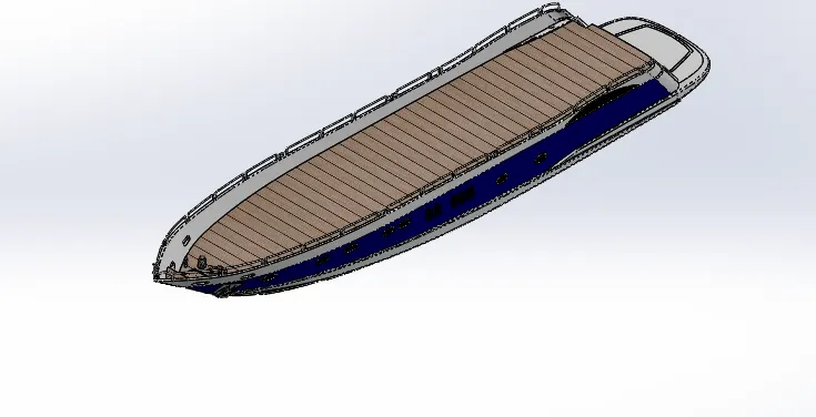
Select the blueprint or creating the hull. By selecting the top view and side view we develop the whole part . very firstly curve is projected surface loft the area by using the midplane. Then surface trim is done. At then extrude the area and knitted the surface. Surface fill the area and again knit the surface and shell is created. The midplane is created and boss the extrude the sketch and cut extrude the sketch .the chamfer and filleted the edges. Select the plane by midplane with some dimension. Then second plane is created swept the sketches. The same process is repeated for several times .Cut extrude the top of the deck surface and boss extruded the area and finally filleted the edges. then plane is created and boss extrude the bottom surface of the hull. The chamfer and filleted the edges. Boss extrude the right corner of deck surface. And revolve the area , dome the surface and helix/spiral is given . Then linear pattern is used on deck surface. The railing reference is created after sweeping the edges. The curve is created for sweeping the surface . Spilt the part for later we use the garage door. Split line is created at the side part of hull. Finally mirror the entire the surface. The appearance is given.
5.SUPER STRUCTURE:
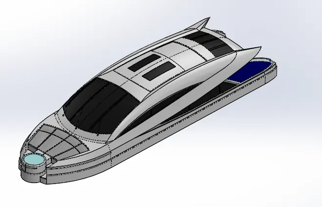
For creating the superstructure surface loft, trim ,knit is most important component . the deck surface is taken as reference plane .select blueprint setup surface extrude the area and plane is formed by using the vertex of the surface and surface sweep the area knitted the surface and fitted the edges. the ruled surface is done and surface trim is created. The curve 1&2 is created for the surface loft. The surface fill is created by closing the edges and knitted the surface. The mirror entire part of superstructure we created . whole solid body is created. Finally appearance is given.
Front seat:
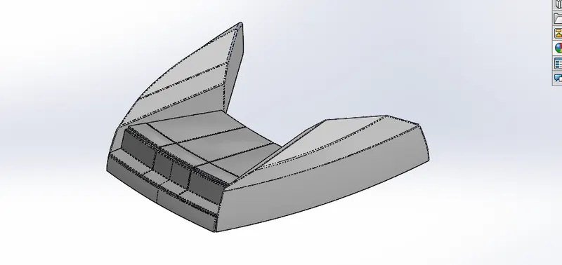
Select the blueprint setup and take the deck surface of the hull. The side portion of the front seat is surface swept by creating the plane. 2D sketch is created for surface extrude and surface trim the area. Fill is created by closing edges. later part unhide the deck surface. Surface loft the side portion trim the area and knit the surface. Filleted and chamfer are created at edges. the appearances is given.
Middle seat:
Deck surface is taken as reference plane. Select the blue print setup and insert the part select the bottom plane and create the sketch boss extrude the area. The plane is created and boss extrude the area. Chamfer and filleted is created. Mirror the whole part we created. At center of the middle seat boss extrude and cut extrude the area. Filleted the edges. the appearances is given.
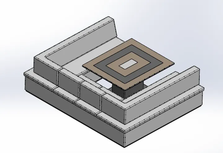
Rear seat:
Again select the blue print setup and insert the deck surface of the hull.
First we create the front portion by surface sweep and surface trim the area. Create the ruled surface and surface knit the area. Surface extend the upper of the rear seat and trim the area. Knit the surface. Surface extrude the side area and surface loft the back portionand knit the surface. Create the sketch, surface loft and surface extend the area. Filleted and chamfer the edges, finally mirror the entire part. The appearance is given.
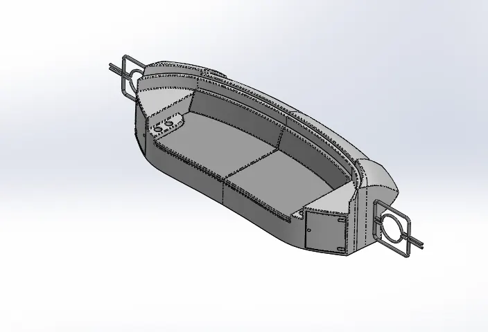
Radar mast:
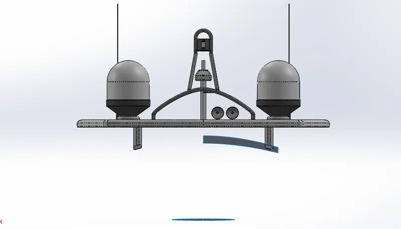
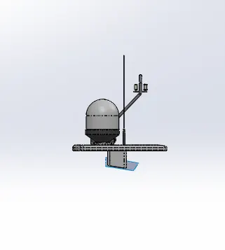
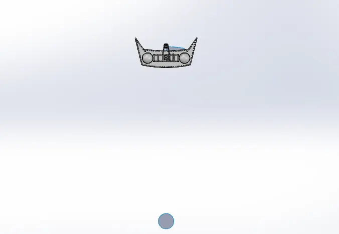
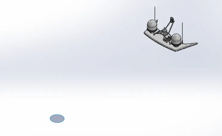
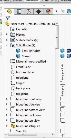
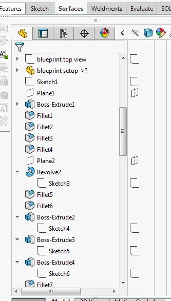
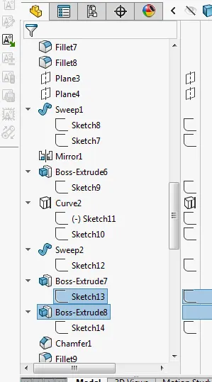
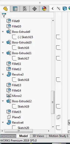
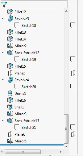
Select the blueprint setup and surface of the superstructure. Plane is created and boss extrude the bottom plane. Filleted the edges. plane is created and revolve the area. Boss extrude from bottom plane and filleted the edges. mirror the sweep area. The curve is projected for sweep the area and again filleted the edges. dome is created at the revolve the area and shell the area. At last mirror the entire part we created. The appearances is given
ASSEMBLY:
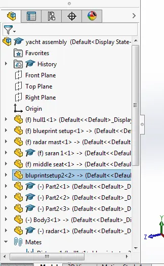
As we take deck surface of hull as a reference plane so automatically coincident with hull and same for the radar mast . first import the hull and super structure ,radarmast,front seat, middle seat, rear seat. It will coincident it. Take the garage door and fix it at rear end. Three propeller is connected at the last and radar at the top of the radarmast.
Rendering:
The final step of the yacht to make it look realistic as we have already discuss the uses of rendering a model here we try to make it look as realistic as it was possible we started off with checking the appearance added on all the parts then we to make it look more stylish camera view setting the desired lights and the focal distance creating the angle of the view and saving the camera angle which gave a realistic view to the yacht. Now we take our assembly file into solid works visualize where we start making the product more and more realistic with adding the background changing the and adjusting the brightness, shadow density and gamma levels according to the different requirements of the different backgrounds changing the color of the model and checking what suits the best with which background until we get the desired and astonishing product ready
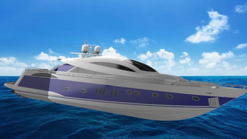
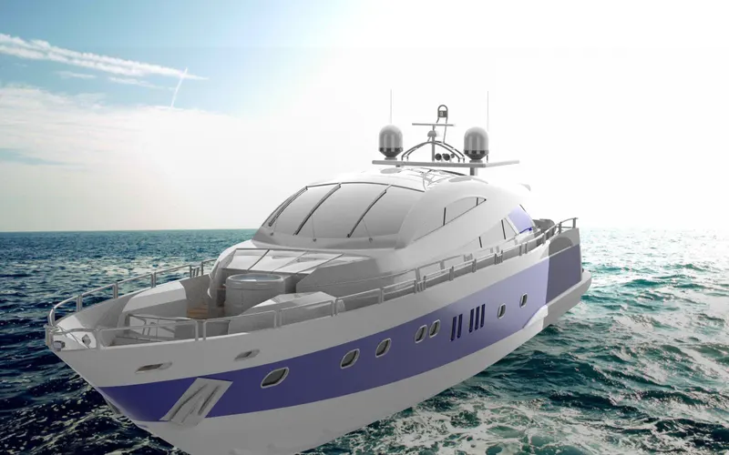
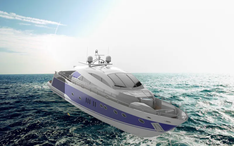
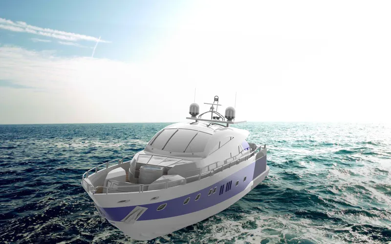

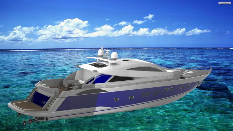
assembly of yacht: