Week 12 Challenge
1. Create alignment plans in sheets.
2. Create roadway double stack plans in sheets.
3. Create plan and profile sheets.
4. Create cross sections sheets.
Q-1 : CREATE ALIGNMENT PLAN SHEET :
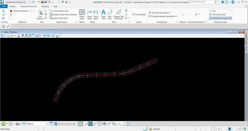
Create a file named as "ALIGNMENT PLAN SHEET" with 2D Seed > Reference the alignment file > Click on Drawing Production tab > Named Boundry > Click on Place Named Boundry > Place Named Boundry Civil Plan open > Drawing Seed : ANSI D_PLAN PLAN > Detail Scale : 1"=100' > Name : ALIGNMENT > Start Location : 00+00 > End Location : 128+39.66 > Length : 1000 > Left Offset: -200 > Right Offset : 200 > Overlap : 00 > Boundry Chord : 20 > Check Create Drawing and Show Dailog > Left Click on Screen > Create Drawing tool open > Set the Scale > Set the Annotation Group > Set the all given option > Check the box to Add to Sheet Index > Left click on screen > Sheet is created.
Q-2 : ROADWAY DOUBLE PLAN SHEET :
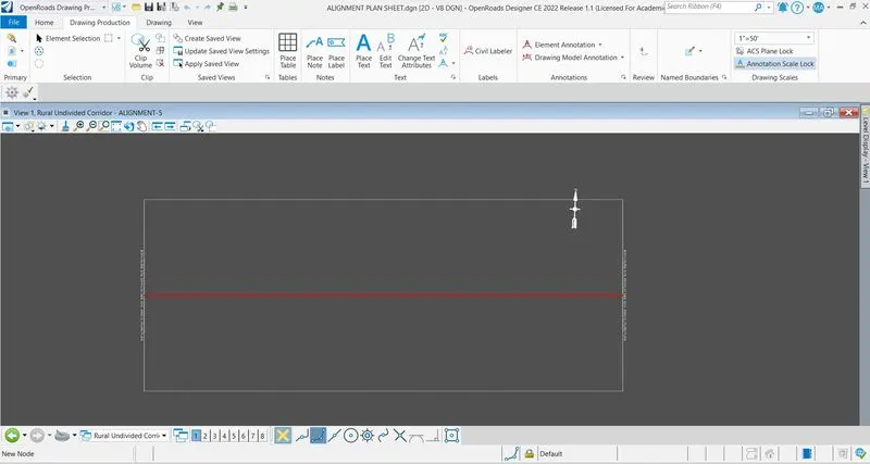
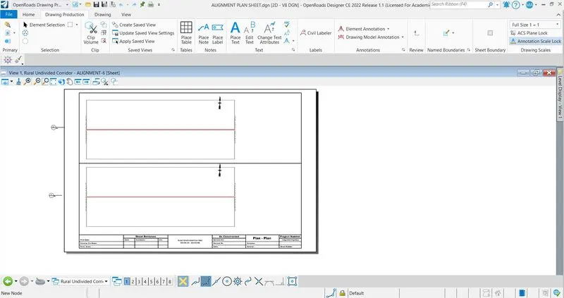
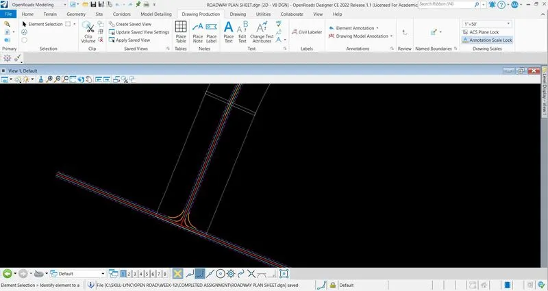
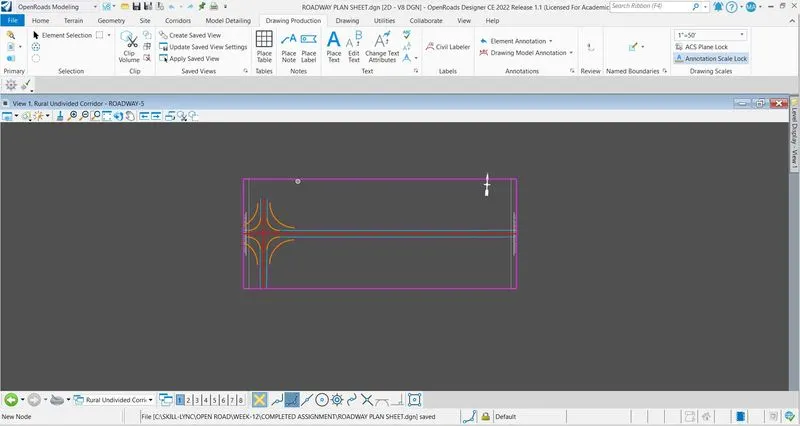
Create a file named as "ROADWAY PLAN SHEET" with 2D Seed > Reference the alignment file as well as Roadway file > Click on Drawing Production tab > Named Boundry > Click on Place Named Boundry > Place Named Boundry Civil Plan open > Drawing Seed : ANSI D_PLAN PLAN > Detail Scale : 1"=50' > Name : ROADWAY > Description : WEEK-12 > Start Location : 00+00 > End Location : 129+90.66 > Length : 1000 > Left Offset: -200 > Right Offset : 200 > Overlap : 20 > Boundry Chord : 20 > Check Create Drawing and Show Dailog > Left Click on Screen > Create Drawing tool open > Set the Scale > Set the Annotation Group > Set the all given option > Check the box to Add to Sheet Index > Left click on screen > Sheet is created.
Q-3 : CREATE PLAN AND PROFILE SHEET :
Create a file named as "PLAN AND PROFILE SHEET" with 2D Seed > Reference the Corridor file with live nesting and nesting depth of 1 > Click on Drawing Production tab > Drawing Seed : ANSI D_Plan-Profile PLAN > DEtail Scale : 1"=20' > Name : PLAN AND PROFILE > Description : WEEK-12 > Start Location : 00+00 > End Location : 66+00 > Length : 560 > Left Offset :-200 > Right Offset : 200 > Overlap : 20 > Boundry Chord : 20 > Left Click on screen > Boundry is created.
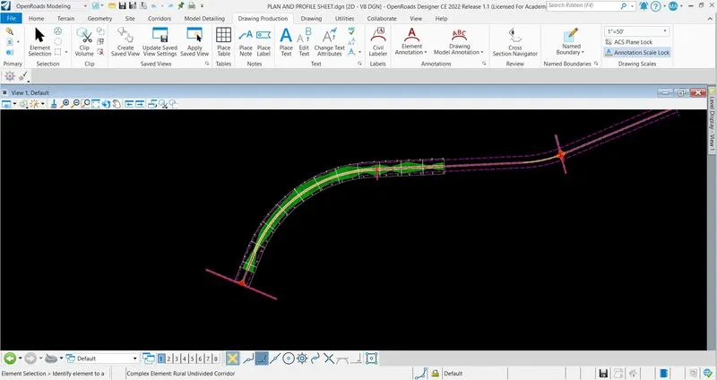
Click on Alignment > Hover on it > Open Profile Model > Select the view tab > Profile Model is opened.
Click on Drawing Production > Named Boundry > Place Named Boundry > Click on Civil Profile > Drawing Seed : ANSI D_Plan-Profile PROFILE 20 Scale > Details Scale : 1"=20' > Name : PLAN AND PROFILE > Description : WEEK-12 > Method from Plan Group > Plan Group : Rural Undivide Corridor-1 > Group : New > Name : Geom BL29 > Description : Group : Rural Undivided Corridor-1 > Vertical Exaggeration : 2 > Available Profile Height : 80 > Top Clearence : 0.5 > Bottom Clearance : 2 > Elevation Datum Spacing : 5 > Station Datum Spacing : 50 > Profile Shifts : Datum Stations > Left Click on screen > Boundry created.
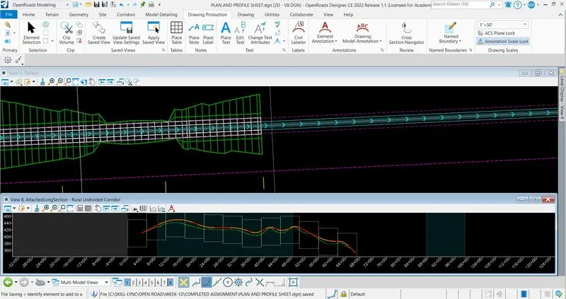
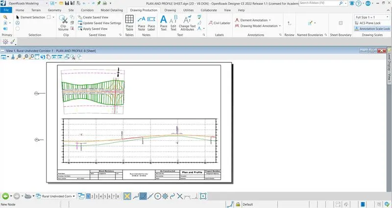
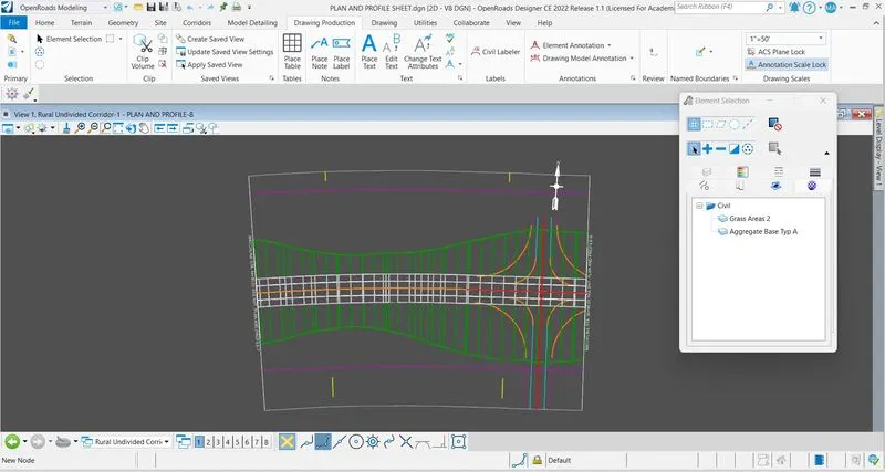
Click on Named Boundries > Expand the Plan Groups > Expand Undivided Corridor-1 > Right click > Create Plan/Profile drawing > Plan Profile Sheet is created.
Q-4 : CREATE CROSS SECTION SHEET :
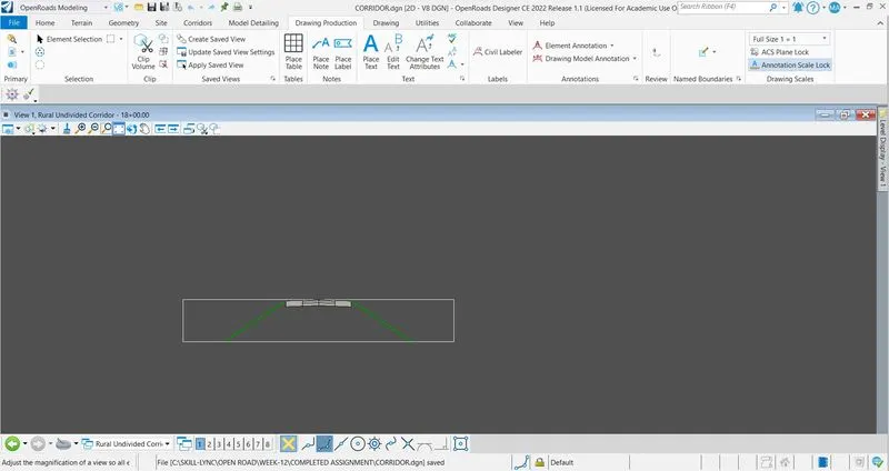
Open Corridor file > Live Nesting is on with Nasting Depth of 1 > Click on Drawing Production tab > Click on Named Boundry > Click on Civil Cross Section > Detail Scale : Full Size 1=1 > Name : Rural Undivided Corridor > Start Location : 00+00 > End Location : 67+98.87 > Left Offset : -100 > Right Offset : 100 > Interval : 200 > Vertical Exaggeration : 2 > Top Clearence : 0.5 > Bottom Clearence : 0.5 > Elevation Datum Spacing : 10 > Left click on screen.
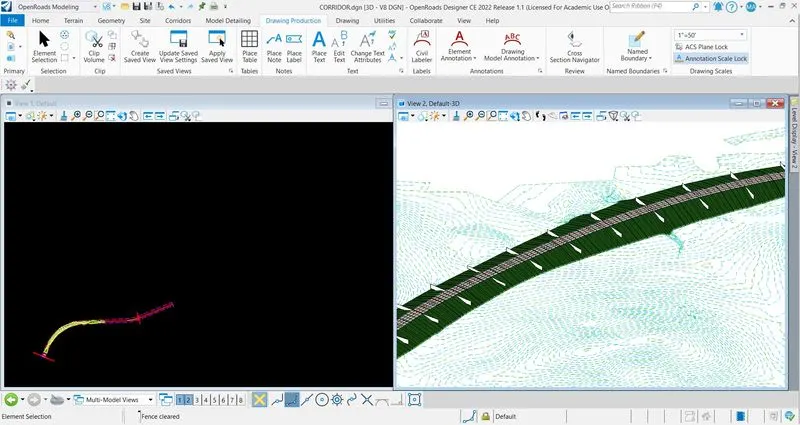
Click on Named Boundry > Expand Section Groups > Right click on Rural Undivided Corridor WEEK-12 > Create Cross section drawing > Cross section sheet is created.