Week 12 Challenge
Aim: To determine the Barge Impact load acting on bridge and analyze accordingly in Staad.Pro.
Introduction:
The objective is to calculate Barge Impact loads from the given data manually and attempt the same in Staad.Pro for the bridge and analyse the results and effects on the structure.
The Illustrated bridge is a bow string girder bridge spanning 12.0 m long in length and width of 7.0 m having rise of 5.0 m allocated to the way for Panamax ship to carry goods to and fro between eastern & western countries.
Given Data (for calculation):
Span of bridge = 12.0 m
Width of carriage way = 7.0 m
Dead Weight tonnage of Panamax vessel = 52500 Tons
Maximum accommodation by ship = 4500 containers
Each container = 6.1 TEU
Speed of Barge = 60 km/hr
Size of Pier = 2.5 m x 2.5 m
Rise of Bridge = 5.0 m
Thickness of deck slab = 500 mm = 0.5 m
Size of Cross beam = 0.75 m x 1.8 m
Hydrodynamic Coefficient (CH) = 1.25
Assumption:
Since the Length of bridge is 12.0 m whereas width of the Panamax is 32.0 m. So, this might only work when bridge is build at some elevation and over some cliff space between it.
This is not specified in question then height of pier can be assumed to be 9.0 m for calculation and analytical results.
Size of Main Girder Beam = 1.0 m x 2.0 m
It is assumed that vessel is easily movable under the bridge.
Size of the Truss member (Bracing and Vertical Strings) = 0.3 m x 0.3 m
Ignoring the Self-weight of the structure and any other live loads.
Procedure:
All the loads are calculated in such a manner as mentioned below,
Hydrodynamic Coefficient (CH) = 1.25
Barge Displacement Tonnage = 52500 DWT
Barge Impact Speed (V) = 60 km/hr. = 16.67 m/s
Barge Collision Energy (KE) = 500 x CH x W x V2 = 500 x 1.25 x 52500 x (16.67)2 = 9118229531 N-m = 9.12 x 10⁹ N-m
Barge Damage Depth, aB = 3100 x ([1 + 1.3 x 10⁻⁷ KE]0.5 -1) = 3100 x ([1 + (1.3 x 10-7 x 9.12 x 109)]0.5 -1) = 103685.89 mm
Since aB > 100 mm
Then, Barge Collision Impact Force (PB)
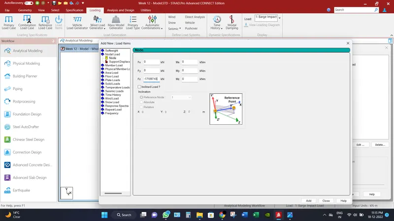
PB = 6.0 x 10⁶ + 1600 x aB = 6.0 x 10⁶ + 1600 x 103685.89 = 171897424 N = 171897.43 KN
Computer Proficiency:
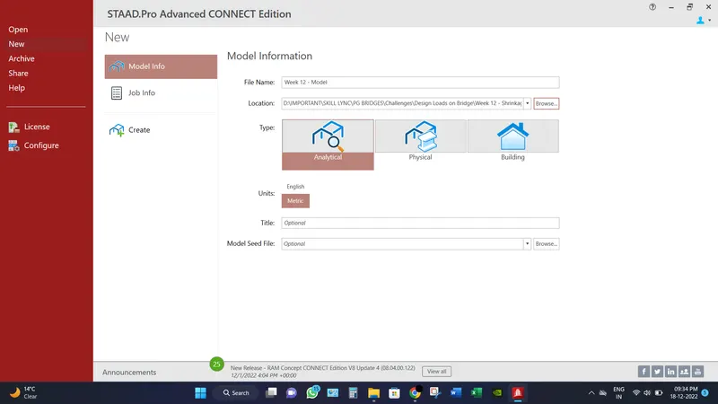
- Create a model by putting the necessary inputs as file location, units etc.
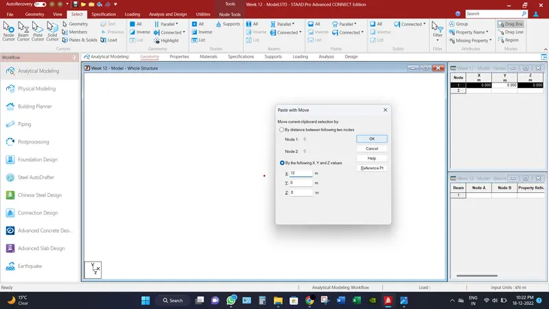
- Create two nodes (x,y,z) represents as (0,0,0) & (12,0,0) Because the length of bridge is 12 m.
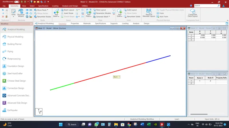
- Go to Add Beams option and connect the both nodes.
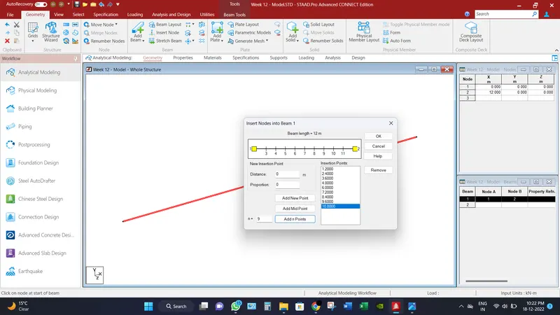
- Go to insert node option and divide the beam into 10 parts by adding 9 nodes in the beam.
- In order to make Bow string of bridge, select the centre most node of beam and replicate it at spacing of 5.0 m in y direction upwards. Because the rise of the bridge is 5.0 m.
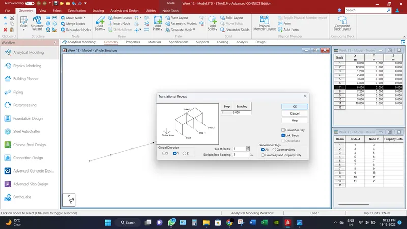
- Similarly, replicate the second node at 1.25 m spacing in y direction.
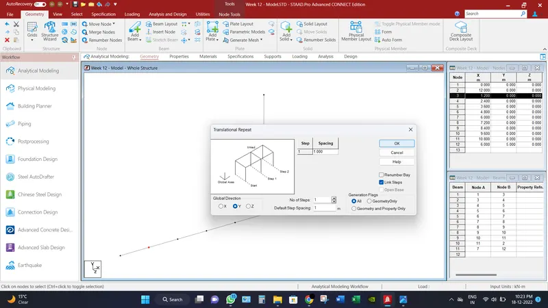
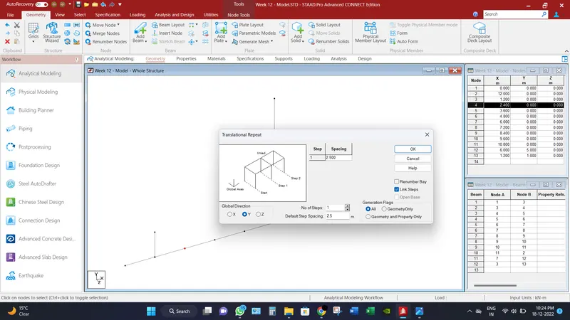
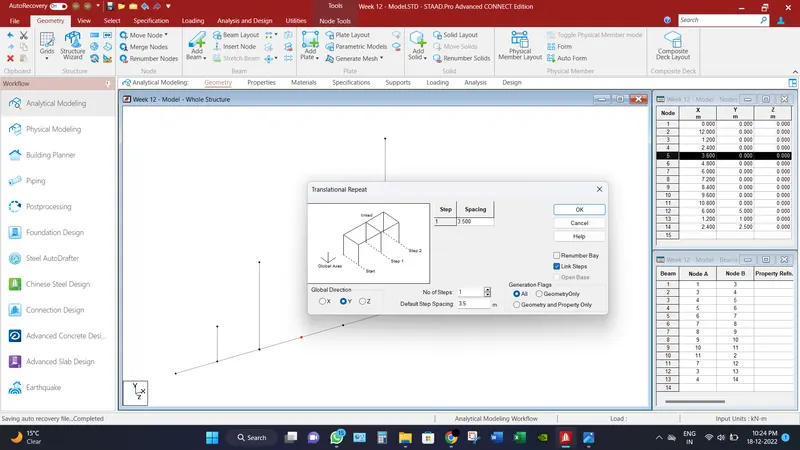
- Similarly, replicate the third, fourth & fifth nodes at 2.5 m, 3.5 m & 4.5 m spacing respectively in y direction.
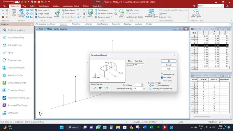
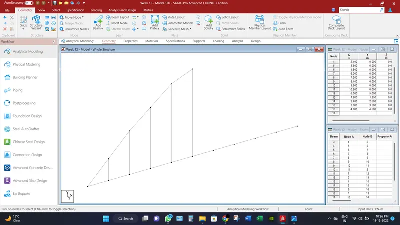
- Connect all the top nodes of the string.
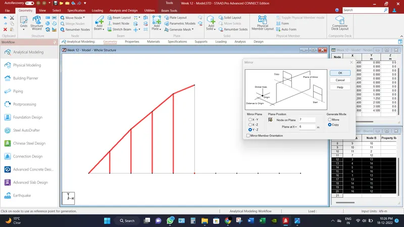
- Replicate the drawn string into different direction by the use of mirror option.
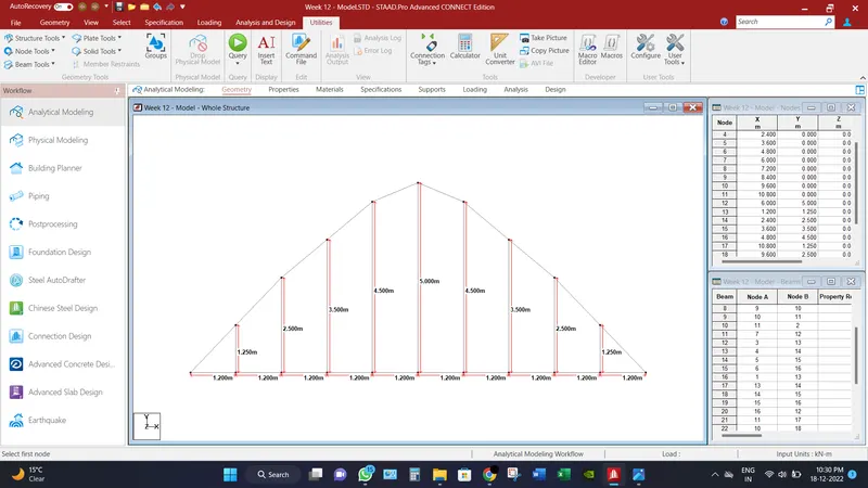
- All the dimension are provided as shown in image below.
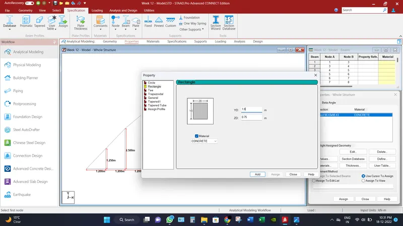
- Go to Properties tab, define the size of girder beam as mentioned above and assign the members accordingly.
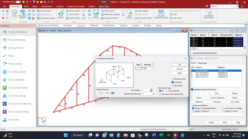
- Select the whole assembly and replicate it into 7.0 m spacing in negative z direction. Because the width of bridge is 7.0 m via link steps.
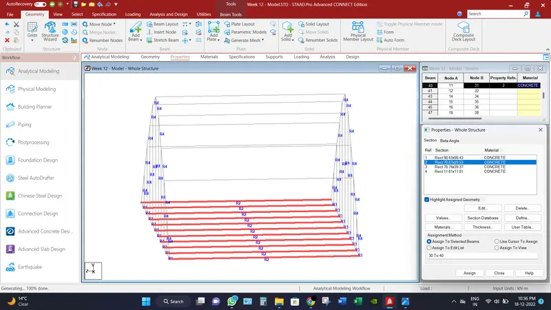
- Assign the size of cross beams as discussed above. And the other parts of bridge accordingly.
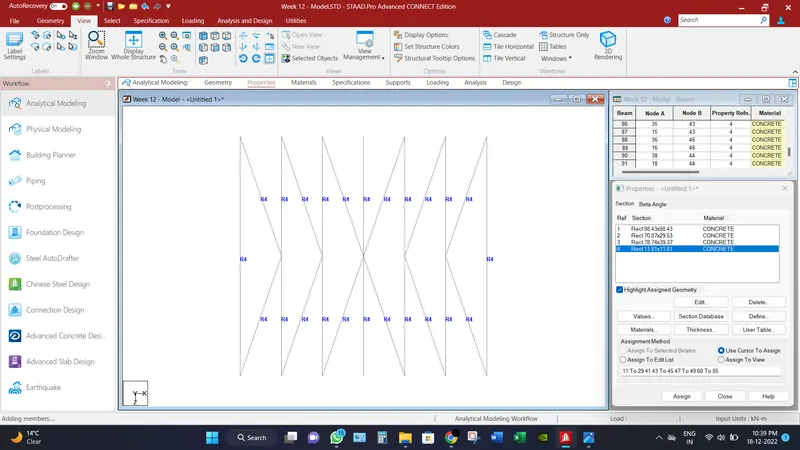
- Go to the top view and draw bracing of bridge as provided in question and assign their sizes accordingly.
- Go to create mesh, and connect corner node of the panel and create quadrilateral mesh of 0.6 m x 0.5 m.
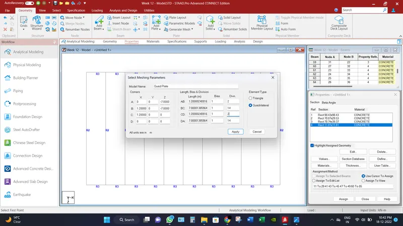
- Assign the thickness of the plate and replicate it into every panel in order to make deck slab.
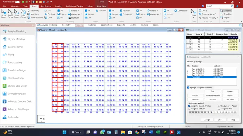
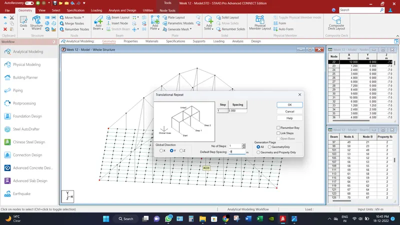
- Select the corner nodes of the bridge and replicate them into 9.0 m spacing via link steps in negative y direction. in order to make pier and assign their sizes as discussed above.
- Go to supports tab, and create fixed support and assign to end of peirs.
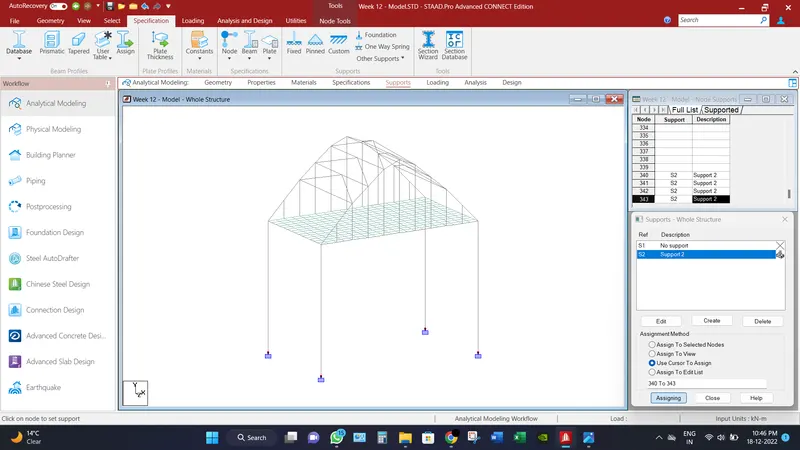
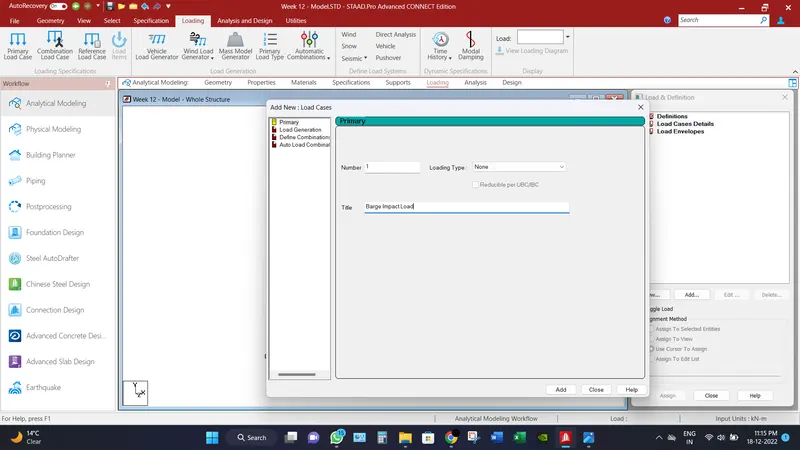
- Go to loading tab, define the Barge Impact load as discussed above and assign to the centre of the main girder beams of bridge. Refer image below.
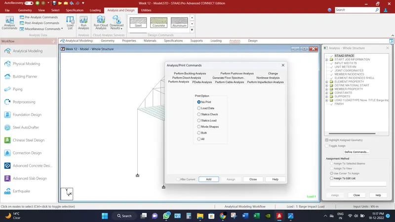
- Then Go to Analysis tab, select Analysis command and add the perform analysis command.
_______________________________________________________________________________________
Analytical Results:
Bridge has been analyzed and check for different load combination and different displacement for different scenarios has been record.
Maximum node displacements is recorded as 122 mm.
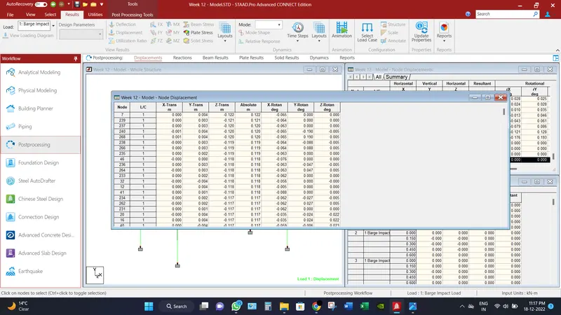
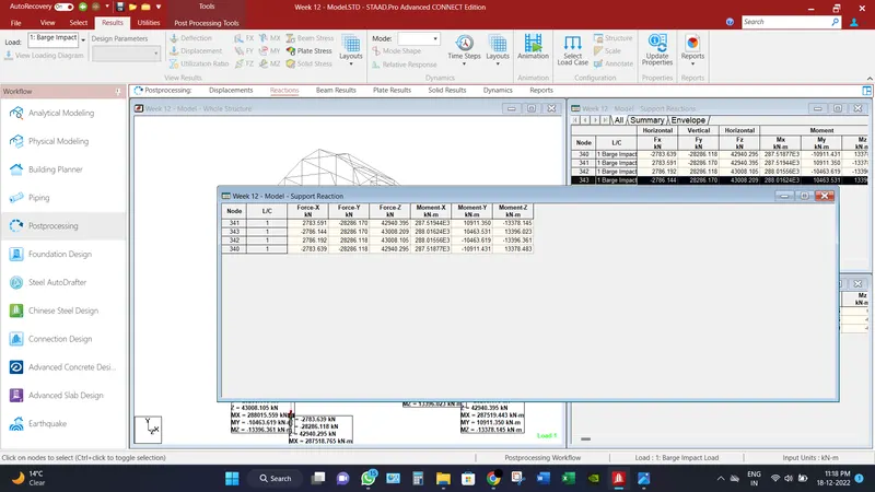
Maximum Base reactions are recorded axial force as 28286.17 KN and moment as 13378.145 KN-m.
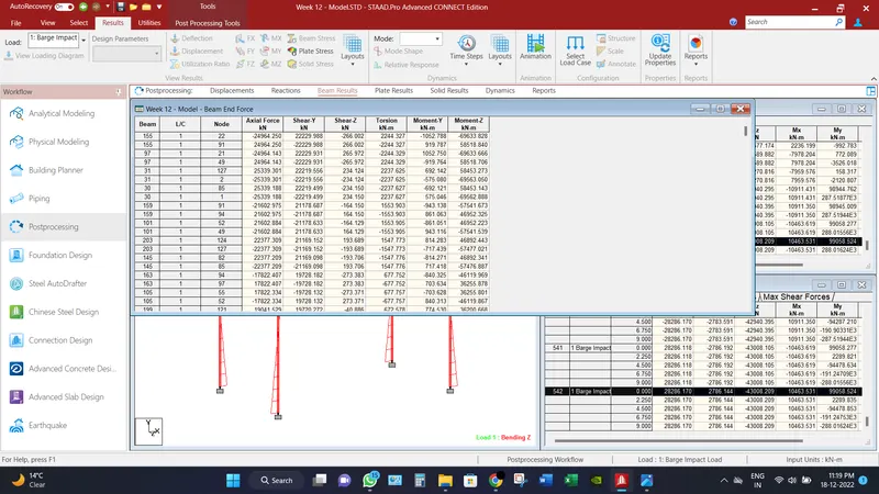
Maximum shear force recorded in beam in Fy direction is 22229.988 KN.
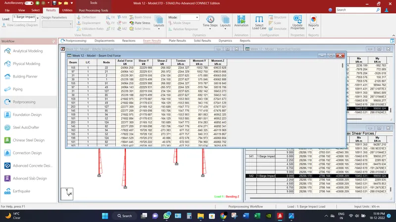
Maximum Bending Moment recorded in beam in Mz direction is 69633.828 KN-m.
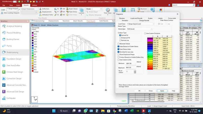
Maximum Shear Force in SQX (local) direction for deck slab is recorded as 6641.83 KN/m2.
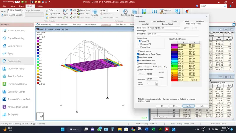
Maximum Shear Force in SQY (local) direction for deck slab is recorded as 7264.96 KN/m2.
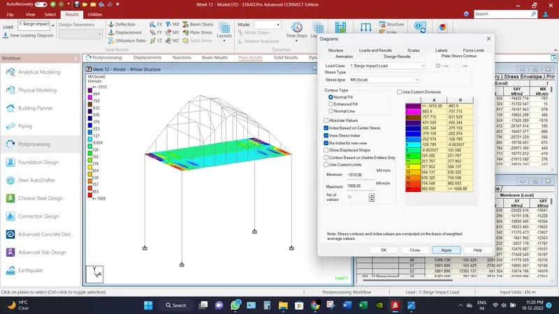
Maximum Moment in MX (local) direction for deck slab is recorded as 1008.88 KN-m/m.
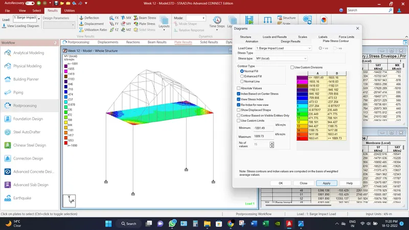
Maximum Moment in MY (local) direction for deck slab is recorded as 1889.73 KN-m/m.
_________________________________________________________________________________
Conclusion:
Different results have been found under the Barge Impact loads,
Maximum node displacements is recorded as 122 mm.
Maximum Base reactions are recorded axial force as 28286.17 KN and moment as 13378.145 KN-m.
Maximum shear force recorded in beam in Fy direction is 22229.988 KN.
Maximum Bending Moment recorded in beam in Mz direction is 69633.828 KN-m.
Maximum Shear Force in SQX (local) direction for deck slab is recorded as 6641.83 KN/m2.
Maximum Shear Force in SQY (local) direction for deck slab is recorded as 7264.96 KN/m2.
Maximum Moment in MX (local) direction for deck slab is recorded as 1008.88 KN-m/m.
Maximum Moment in MY (local) direction for deck slab is recorded as 1889.73 KN-m/m.