Week 12.1: 2D Cavitation simulation
2D Cavitation Simulation
- Aim:
1) Set up and run 3 cases for Winkl Hoffer Nozzle to study Cavitation,
- Case 1: Set up the case for Pressure difference of 30 bars
- Case 2: Set up the case for Pressure difference of 70 bars
- Case 3: Set up the case for Pressure difference of 100 bars
2) Post process results in Paraview:
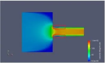
- Plot contours for Velocity
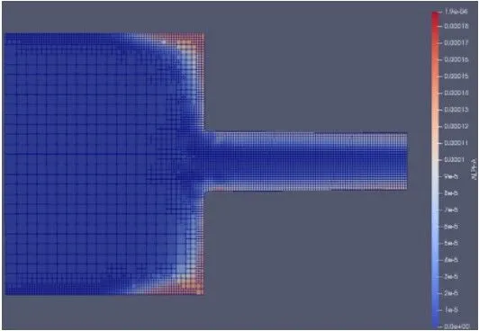
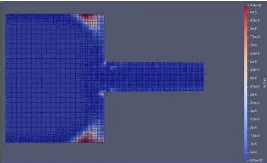
- Plot contour for void fraction
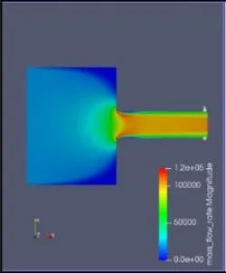
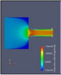
- Plot contour for mass flow rate
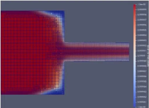
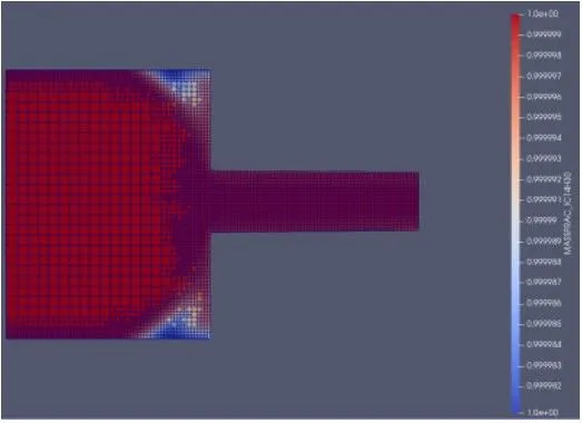
- plot contour for mass fraction
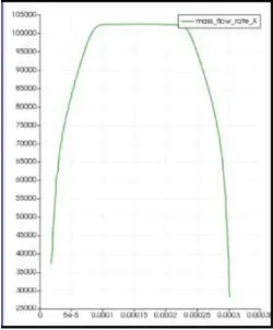
3) For all the 3 cases, create a LINE PROBE (i.e plot over line) at outlet and plot "mass flow rate" over this LINE PROBE.
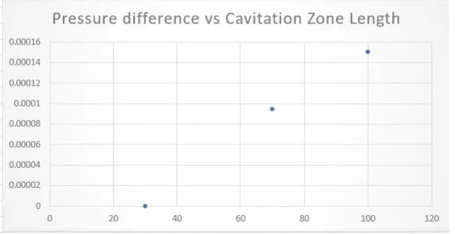
4) Make a plot in excel for Pressure difference Vs Cavitation zone length i.e plot cavitation zone length for pressure difference of 30 bars, 70 bars and 100 bars.
- Theory:
1. Cavitation:
Cavitation is a phenomenon in which the static pressure of a liquid reduces to below the liquid's vapour pressure, leading to the formation of small vapor-filled cavities in the liquid. When subjected to higer pressure, these cavities, called "bubbles" or "voids", collapse and can generate shock waves that may damage machinery. These shock waves are strong when they are very close to the imploded bubble, but rapidly weaken as they propagate away from the implosion.
Cavitation is a significant cause of wear in some engineering contexts. Collapsing voids that implode near to a metal surface cause cyclic stress through repeated implosion. This results in surface fatigue of the metal causing a type of wear also called "cavitation". The most common examples of this kind of wear are to pump impellers, and bends where a sudden change in the direction of liquid occurs. Cavitation is usually divided into two classes of behavior: inertial (or transient) cavitation and non-inertial cavitation.
The process in which a void or bubble in a liquid rapidly collapses, producing a shock wave, is called inertial cavitation. Inertial cavitation occurs in nature in the strikes of mantis shrimps and pistol shrimps, as well as in the vascular tissues of plants. In artificial objects, it can occur in control valves, pumps, propellers and impellers.
Non-inertial cavitation is the process in which a bubble in a fluid is forced to oscillate in size or shape due to some form of energy input, such as an acoustic field. Such cavitation is often employed in ultrasonic cleaning baths and can also be observed in pumps, propellers, etc.
Since the shock waves formed by collapse of the voids are strong enough to cause significant damage to parts, cavitation is typically an undesirable phenomenon in machinery (although desirable if intentionally used, for example, to sterilize contaminated surgical instruments, break down pollutants in water purification systems, emulsify tissue for cataract surgery or kidney stone lithotripsy, or homogenize fluids). It is very often specifically avoided in the design of machines such as turbines or propellers, and eliminating cavitation is a major field in the study of fluid dynamics. However, it is sometimes useful and does not cause damage when the bubbles collapse away from machinery, such as in supercavitation.
Cavitation modelling is a type of computational fluid dynamic (CFD) that represents the flow of fluid during cavitation. It covers a wide range of applications, such as pumps, water turbines, pump inducers, and fuel cavitation in orifices as commonly encountered in fuel injection systems.
`frac[Dx][Dt]=frac[barx-x][theta`
Where, `theta`is the relaxation time scale. In this study, cavitation and condensation are assumed to occur at equal time scales, and are calculated as `theta=theta_oalpha^-0.54 psi^-1.76`, Where, `theta_0` is a co-efficient set to 3.84e-7, `alpha` is the total void fraction, including fuel vapour and non-condensable gases, and `psi`is the non-dimensional pressure ratio,
`psi=frac[p_(sat)-p][p_(crit)-p_(sat)`
- Procedure:
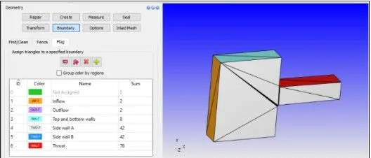
- Geometry:
The following geometry was preprocessed and necessary boundary flagging was assigned.
-Case setup:
- Simulation type:
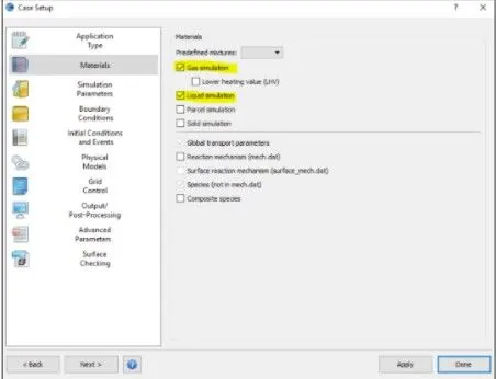
From the above image, the reason behind enabling both gas and liquid simulation is because we are simulating Multiphase simulation.
- Materials:
Liquid tetradecane(IC14H30)
Gas tetradecane(C14H30)
Initially in the domain, there will be only liquid tetradecane and when the cavitation occurs the liquid tetradecane (IC14H30) will be converted into gas tetradecane(C14H30)
- Solver: Transient solver
- Simulation mode: full hydrodynamic
- Region and Initialisation:
We have created a region of the fluid and initialse the pressure as 106Pa and also the species value as IC14H30= 0.99998 and N2=2e-05
- Boundary Conditions:
At 300K
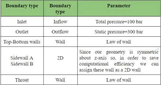
From the above table, we can see that there is a huge Pressure drop which is around 70 bar and this pressure will drive the velocity very high and this form simulation as velocity based CFL number the max convection CFL limit should not be more than 0.5 which can be seen below
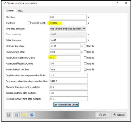
start time: 0sec
End time: 0.02
- Physical Model:
Turbulence model: K-epsilon
VOF Model: Basic VOF
- Grid Control:
Element size: dx=dy=dz=4e-5m
AMR:
Velocity Based AMR:
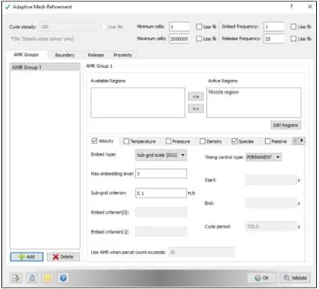
Species Based AMR:
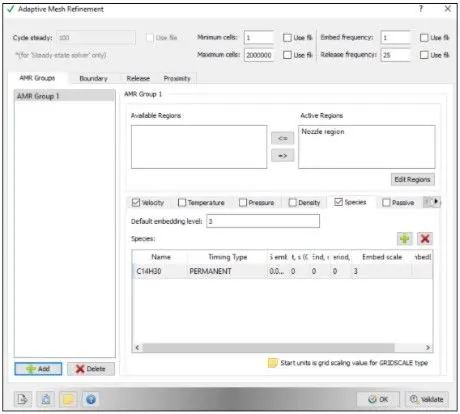
Fixed Embedding:
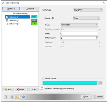
- Output Files:
3D output data files: 5e-05 sec
Writing text output: 1e-10sec
Restart output files: 1e-05 cycles
Max number restart files: 5
- Results:
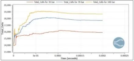
- Mesh:
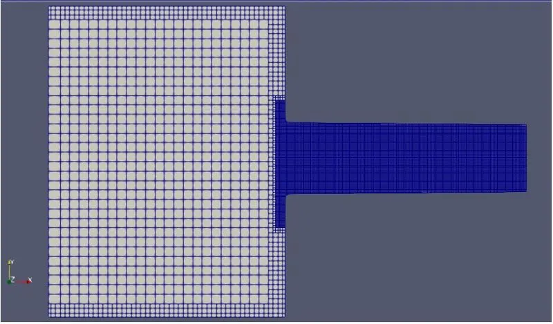
- Total cell count:
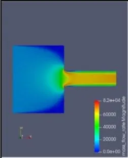
- Case1: Pressure difference 30bar
1. Mass flowrate:
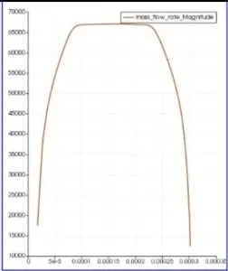
Plot over line at the outlet:
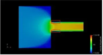
2. Velocity:
3. Alpha (void fraction):
4. Mass fraction:
Case2: Pressure difference of 70bar
1. Mass flowrate:
Plot over line at outlet:
2. Velocity contour:
3. Mass fraction:
4. Void Fraction:
Case3: Pressure difference of 100bar
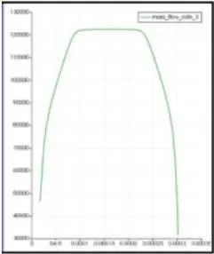
1. Mass flowrate:
Plot over line at outlet:
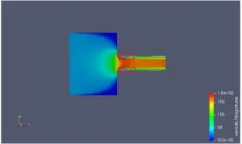
2. Velocity contour:
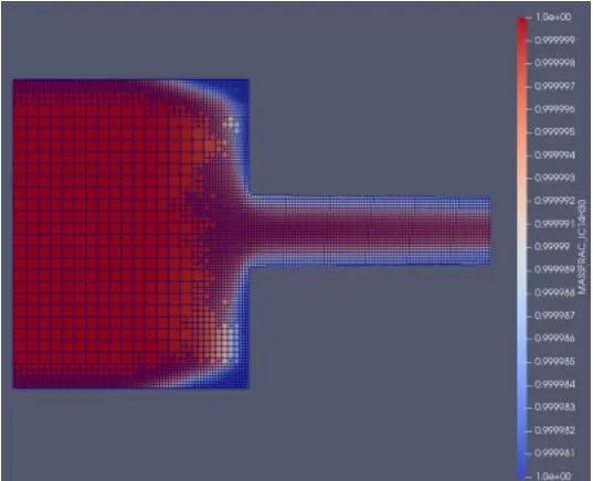
3. Mass fraction:
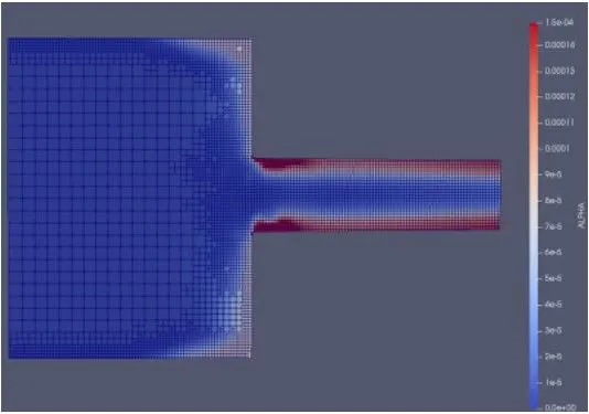
4. Void Fraction:
- Pressure difference Vs Cavitation zone length
- Conclusion:
Successfully performed 2D cavitation simulation using Winkl-Hoffer nozzle as a model, also studied how cavitation occures in injectors and effect of cavitation in system performance.
It is observed as pressure difference increases, cavitation scale also increases.
Therefore, it is necessary to use an optimal massflowrate to minimise cavitation.