Simulation of Flow through a pipe in OpenFoam
- AIM:
To simulate Hagen-Poiseuille's flow in OpenFOAM by considering a part of the pipe(wedge) which is having a wedge angle of less than 5 degrees and also to code the blockMeshDict file using Matlab, so that the same file can be used for different variables to simulate in OpenFOAM.
- OBJECTIVE:
- Write a program in Matlab that can generate the computational mesh automatically for any wedge angle and grading schemes
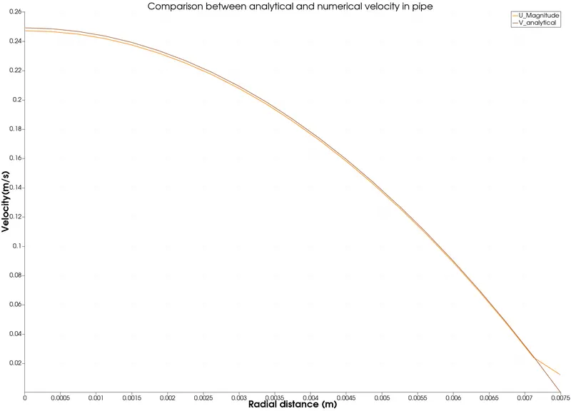
- For a baseline mesh, show that the velocity profile matches with the Hagen poiseuille's equation
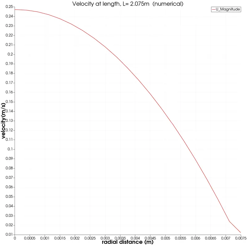
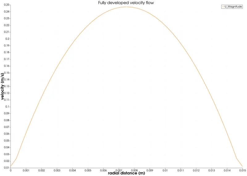
- Show that the velocity profile is fully developed
- Post-process velocity and shear stress
- CONTENT:
1. Hagen-Poiseuille's law:
In nonideal fluid dynamics, the Hagen–Poiseuille equation, also known as the Hagen–Poiseuille law, Poiseuille law or Poiseuille equation, is a physical law that gives the pressure drop in an incompressible and Newtonian fluid in laminar flow flowing through a long cylindrical pipe of constant cross-section. It can be successfully applied to airflow in lung alveoli, or the flow through a drinking straw or through a hypodermic needle. It was experimentally derived independently by Jean Léonard Marie Poiseuille in 1838 and Gotthilf Heinrich Ludwig Hagen, and published by Poiseuille in 1840–41 and 1846. The theoretical justification of the Poiseuille law was given by George Stokes in 1845.
The assumptions of the equation are that the fluid is incompressible and Newtonian; the flow is laminar through a pipe of constant circular cross-section that is substantially longer than its diameter, and there is no acceleration of fluid in the pipe. For velocities and pipe diameters above a threshold, actual fluid flow is not laminar but turbulent, leading to larger pressure drops than calculated by the Hagen–Poiseuille equation.
The standard equation for laminar flow inside a pipe is given by,
`DeltaP = (8pimuLQ)/(A^2)`
where:
- Δp is the pressure difference between the two ends
- L is the length of pipe,
- μ is the dynamic viscosity
- Q is the volumetric flow rate
- R is the pipe radius
- A is the cross-section of the pipe
2. Wedge geometry:
We are dealing with the flow in a pipe having a laminar flow, i.e. Re <= 2300.
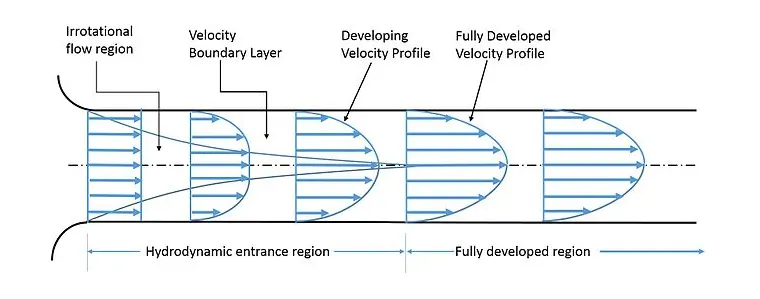
We are going to consider a portion of the pipe, which forms a wedge shape and since the wedge angle is very small there is no need to consider the arc of the wedge. The geometry of the wedge is as follows,
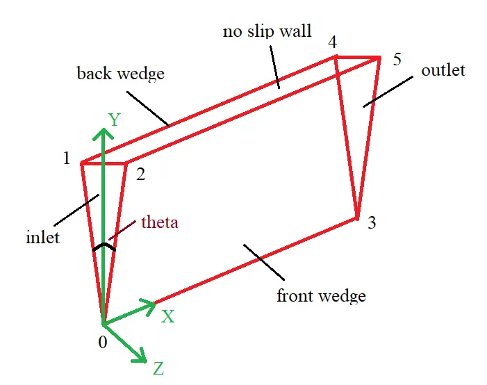
The characteristic length of the wedge is calculated depending on the diameter of the pipe and the Re number considered w.r.t flow.
In this case,
The Reynolds number is taken to be 2100.
The diameter of the pipe is 15mm.
`L_p = L_e + 0.5`
Where,
`L_p` is Length of the pipe
`L_e` is the hydrodynamic length
The length of the pipe is calculated by,
`L_e= 0.05*Re*D`
Where,
D is the diameter of the pipe
Re is Reynolds number
The `V_(avg)` is calculated by using the Reynolds number equation,
`Re= (rho*V_(avg) *D)/ mu`
this can be re-written as,
`V_(avg)= (Re* mu)/(rho* D)`
Where,
Re is reynolds number (in this case, Re= 2100)
`mu` is the dynamic viscosity
`rho` is the density of fluid
D is the diameter of the pipe
therefore, considering this case for Re= 2100 we get the average velocity as,
`V_(avg)= 0.1246 m/s`
Maximum velocity,
`V_max = 2* V_(avg)`
The equation for calculating Analtyical Velocity is,
`V = V_max * (1- r^2/R^2)`
3. Initial and boundary conditions:
The initial conditions at the inlet patch,
velocity is given as the average velocity,
pressure as zeroGradient,
Boundary conditions,
At the inlet wall, the velocity and noSlip condition are entered, outlet wall is gonna have pressure variable as uniform 0 and no noSlip condition.
4. Procedure:
1. Copy the cavity case file from icoFoam solver which is found in tutorials to your required folder so that the case file can be edited accordingly.
2. The blockMeshDict is edited as the required geometry is needed to be created, in this case we are going to create a wedge with a wedge angle of 4.5 degrees.
3. After creating the required geometry in the blockMeshDict, run the blockMesh command to check the geometry of the wedge.
4. The generated mesh is as follows,
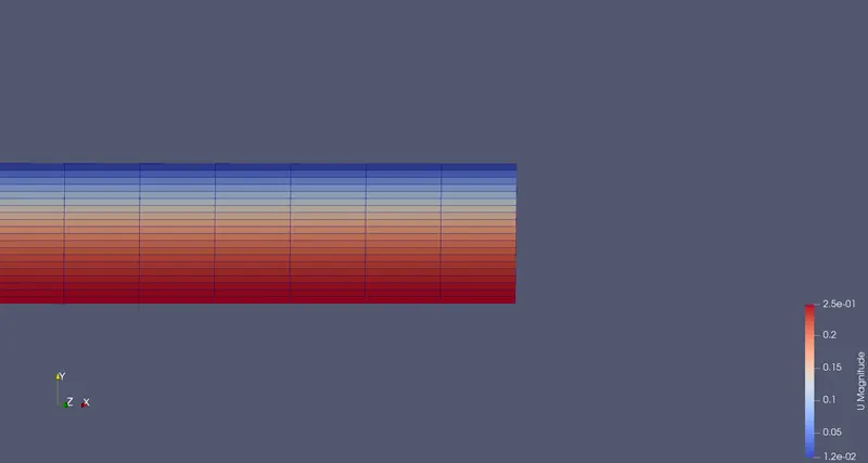
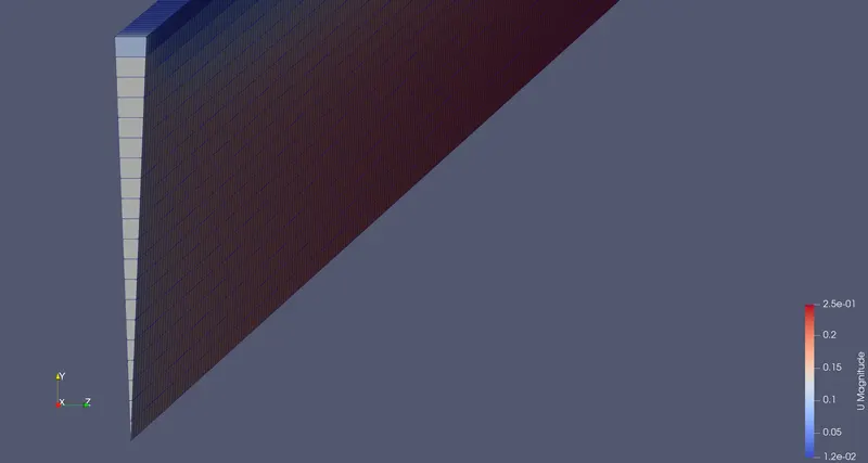
5. After the geometry is created properly, enter the initial conditions and boundary conditions in the 0 file respectively and also enter kinematic viscosity value in transportproperties text file.
6. Run the simulation using the icoFoam solver after calculating the time needed for the fluid to travel from inlet to outlet.
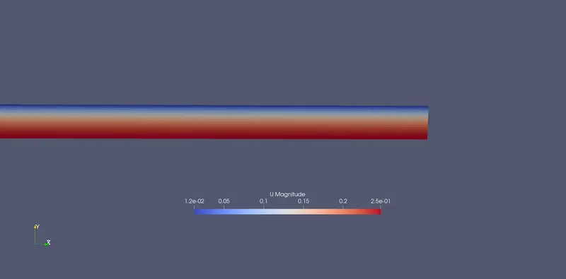
7. After the simulation, use paraFoam to view the flow inside the wedge and use plot over line command to plot the velocity and shear stress changes at a point after the hydrodynamical entry region so that we analyse the fully developed region of the fluid.
8. Use Matlab to parse the blockMeshDict so that the same file can be used for any wedge values.
5. programs:
1. MATLAB file writing code:
%parsing a blockMeshDict of flow in a pipe( hagen-poisuelle flow)

clear all
close all
clc

%specifying the inputs
d= 0.015;
r= d/2;
theta= 4.5;
Re= 2100;
L_hydro = 00.05*Re*d;
L_pipe= L_hydro + 0.5;
scale= 1;

%co-ordinates of vertices
v0= [0 0 0];
v1= [0 r*cosd(theta/2) r*sind(theta/2)];
v2= [0 r*cosd(theta/2) -r*sind(theta/2)];
v3= [L_pipe 0 0];
v4= [L_pipe r*cosd(theta/2) r*sind(theta/2)];
v5= [L_pipe r*cosd(theta/2) -r*sind(theta/2)];

%number of cells along x,y and z axis
nx= 20;
ny= 1;
nz= 500;

%grading factors
gx= 1;
gy= 1;
gz= 1;

%writing to a file
f1 = fopen('blockMeshDict_parsed.txt','w');

%header region
fprintf(f1,'%sn','/*--------------------------------*- C++ -*----------------------------------*');
fprintf(f1,'%sn','  =========                 |');
fprintf(f1,'%sn','  \      /  F ield         | OpenFOAM: The Open Source CFD Toolbox');
fprintf(f1,'%sn','   \    /   O peration     | Website:  https://openfoam.org');
fprintf(f1,'%sn','    \  /    A nd           | Version:  8');
fprintf(f1,'%sn','     \/     M anipulation  |');
fprintf(f1,'%sn','*---------------------------------------------------------------------------*/');
fprintf(f1,'%sn','FoamFile');
fprintf(f1,'%sn','{');
fprintf(f1,'%sn','    version     2.0;');
fprintf(f1,'%sn','    format      ascii;');
fprintf(f1,'%sn','    class       dictionary;');
fprintf(f1,'%sn','    object      blockMeshDict;');
fprintf(f1,'%sn','}');
fprintf(f1,'%sn','// * * * * * * * * * * * * * * * * * * * * * * * * * * * * * * * * * * * * * //');
fprintf(f1,'n');

%initial inputs
fprintf(f1,'%s','convertToMeters ');
fprintf(f1,'%gn',scale );
fprintf(f1,'n');
fprintf(f1,'%sn','vertices');
fprintf(f1,'(n');
fprintf(f1,'    (%d %d %d)n',v0);
fprintf(f1,'    (%g %g %g)n',v1);
fprintf(f1,'    (%g %g %g)n',v2);
fprintf(f1,'    (%g %g %g)n',v3);
fprintf(f1,'    (%g %g %g)n',v4);
fprintf(f1,'    (%g %g %g)n',v5);
fprintf(f1,');nn');

%Defining the wedge block
fprintf(f1,'%sn','blocks');
fprintf(f1,'(n');
fprintf(f1,'    %s (%g %g %g %g %g %g %g %g)','hex (0 2 1 0 3 5 4 3)');
fprintf(f1,'%g %g %g)',nx,ny,nz);
fprintf(f1,' %s (%g %g %g)n','simpleGrading',gx,gy,gz);
fprintf(f1,');');
fprintf(f1,'nn');

%edges (if needed to add arc, etc.)
fprintf(f1,'%sn','edges');
fprintf(f1,'(n');
fprintf(f1,');nn');

%Boundary Conditions
fprintf(f1,'%sn','boundary');
fprintf(f1,'(n');

%Inletwall
fprintf(f1,'    %sn','inletWall');
fprintf(f1,'    {n');
fprintf(f1,'        %sn','type patch;');
fprintf(f1,'        %sn','faces');
fprintf(f1,'        (n');
fprintf(f1,'            %sn','(0 1 2 0)');
fprintf(f1,'        );n');
fprintf(f1,'    }n');

%Outlet wall
fprintf(f1,'    %sn','outletWall');
fprintf(f1,'    {n');
fprintf(f1,'        %sn','type patch;');
fprintf(f1,'        %sn','faces');
fprintf(f1,'        (n');
fprintf(f1,'            %sn','(3 5 4 3)');
fprintf(f1,'        );n');
fprintf(f1,'    }n');

%Front wall
fprintf(f1,'    %sn','front');
fprintf(f1,'    {n');
fprintf(f1,'        %sn','type wedge;');
fprintf(f1,'        %sn','faces');
fprintf(f1,'        (n');
fprintf(f1,'            %sn','(0 3 4 1)');
fprintf(f1,'        );n');
fprintf(f1,'    }n');

%Back wall
fprintf(f1,'    %sn','Back');
fprintf(f1,'    {n');
fprintf(f1,'        %sn','type wedge;');
fprintf(f1,'        %sn','faces');
fprintf(f1,'        (n');
fprintf(f1,'            %sn','(5 3 0 2)');
fprintf(f1,'        );n');
fprintf(f1,'    }n');

%Top wall
fprintf(f1,'    %sn','topwall');
fprintf(f1,'    {n');
fprintf(f1,'        %sn','type wall;');
fprintf(f1,'        %sn','faces');
fprintf(f1,'        (n');
fprintf(f1,'            %sn','(1 4 5 2)');
fprintf(f1,'        );n');
fprintf(f1,'    }n');

%Bottom wall
fprintf(f1,'    %sn','bottomwall');
fprintf(f1,'    {n');
fprintf(f1,'        %sn','type empty;');
fprintf(f1,'        %sn','faces');
fprintf(f1,'        (n');
fprintf(f1,'            %sn','(3 0 0 3)');
fprintf(f1,'        );n');
fprintf(f1,'    }n');
fprintf(f1,');nn');

%Merging Patch pairs
fprintf(f1,'%sn','mergePatchPairs');
fprintf(f1,'(n');
fprintf(f1,');nn');
fprintf(f1,'%s','// ************************************************************************* //');


fclose(f1)
2. blockMeshDict parsed file:
/*--------------------------------*- C++ -*----------------------------------*
  =========                 |
  \      /  F ield         | OpenFOAM: The Open Source CFD Toolbox
   \    /   O peration     | Website:  https://openfoam.org
    \  /    A nd           | Version:  8
     \/     M anipulation  |
*---------------------------------------------------------------------------*/
FoamFile
{
    version     2.0;
    format      ascii;
    class       dictionary;
    object      blockMeshDict;
}
// * * * * * * * * * * * * * * * * * * * * * * * * * * * * * * * * * * * * * //

convertToMeters 1

vertices
(
    (0 0 0)
    (0 0.00749422 0.000294449)
    (0 0.00749422 -0.000294449)
    (2.075 0 0)
    (2.075 0.00749422 0.000294449)
    (2.075 0.00749422 -0.000294449)
);

blocks
(
    hex (0 2 1 0 3 5 4 3) (20 1 500) simpleGrading (1 1 1)
);

edges
(
);

boundary
(
    inletWall
    {
        type patch;
        faces
        (
            (0 1 2 0)
        );
    }
    outletWall
    {
        type patch;
        faces
        (
            (3 5 4 3)
        );
    }
    front
    {
        type wedge;
        faces
        (
            (0 3 4 1)
        );
    }
    Back
    {
        type wedge;
        faces
        (
            (5 3 0 2)
        );
    }
    topwall
    {
        type wall;
        faces
        (
            (1 4 5 2)
        );
    }
    bottomwall
    {
        type empty;
        faces
        (
            (3 0 0 3)
        );
    }
);

mergePatchPairs
(
);

// ************************************************************************* //
3. controlDict file:
/*--------------------------------*- C++ -*----------------------------------*
  =========                 |
  \      /  F ield         | OpenFOAM: The Open Source CFD Toolbox
   \    /   O peration     | Website:  https://openfoam.org
    \  /    A nd           | Version:  8
     \/     M anipulation  |
*---------------------------------------------------------------------------*/
FoamFile
{
    version     2.0;
    format      ascii;
    class       dictionary;
    location    "system";
    object      controlDict;
}
// * * * * * * * * * * * * * * * * * * * * * * * * * * * * * * * * * * * * * //

application     icoFoam;

startFrom       startTime;

startTime       0;

stopAt          endTime;

endTime         20;

deltaT          1e-2;

writeControl    timeStep;

writeInterval   20;

purgeWrite      0;

writeFormat     ascii;

writePrecision  6;

writeCompression off;

timeFormat      general;

timePrecision   6;

runTimeModifiable true;


// ************************************************************************* //
4. TransportProperties file:
/*--------------------------------*- C++ -*----------------------------------*
  =========                 |
  \      /  F ield         | OpenFOAM: The Open Source CFD Toolbox
   \    /   O peration     | Website:  https://openfoam.org
    \  /    A nd           | Version:  8
     \/     M anipulation  |
*---------------------------------------------------------------------------*/
FoamFile
{
    version     2.0;
    format      ascii;
    class       dictionary;
    location    "constant";
    object      transportProperties;
}
// * * * * * * * * * * * * * * * * * * * * * * * * * * * * * * * * * * * * * //

nu              [0 2 -1 0 0 0 0] 8.9e-6;


// ************************************************************************* //
5. initial pressure and velocity files:
i. U:
/*--------------------------------*- C++ -*----------------------------------*
  =========                 |
  \      /  F ield         | OpenFOAM: The Open Source CFD Toolbox
   \    /   O peration     | Website:  https://openfoam.org
    \  /    A nd           | Version:  8
     \/     M anipulation  |
*---------------------------------------------------------------------------*/
FoamFile
{
    version     2.0;
    format      ascii;
    class       volVectorField;
    object      U;
}
// * * * * * * * * * * * * * * * * * * * * * * * * * * * * * * * * * * * * * //

dimensions      [0 1 -1 0 0 0 0];

internalField   uniform (0 0 0);

boundaryField
{
    inletWall
    {
        type            fixedValue;
        value           uniform (0.124 0 0);
    }

    outletWall
    {
        type            zeroGradient;
    }

    front
    {
    	type		wedge;
    }

    Back
    {
        type           wedge;
    }

    topwall
    {
    	type		noSlip;
    }

    bottomwall
    {
    	type		empty;
    }
}

// ************************************************************************* //
ii. P:
/*--------------------------------*- C++ -*----------------------------------*
  =========                 |
  \      /  F ield         | OpenFOAM: The Open Source CFD Toolbox
   \    /   O peration     | Website:  https://openfoam.org
    \  /    A nd           | Version:  8
     \/     M anipulation  |
*---------------------------------------------------------------------------*/
FoamFile
{
    version     2.0;
    format      ascii;
    class       volScalarField;
    object      p;
}
// * * * * * * * * * * * * * * * * * * * * * * * * * * * * * * * * * * * * * //

dimensions      [0 2 -2 0 0 0 0];

internalField   uniform 0;

boundaryField
{
    inletWall
    {
        type            zeroGradient;
    }

    outletWall
    {
        type           fixedValue;
        value		uniform 0;
    }

    front
    {
    	type		wedge;
    }

    Back
    {
        type           wedge;
    }

    topwall
    {
    	type 		zeroGradient;
    }

    bottomwall
    {
    	type		empty;
    }
}

// ************************************************************************* //
6. Results and discussions:
1. Velocity :
Velocity at the fully developed flow
Plots related to velocity:
a. Numerical Velocity:
b. Comparison with analytical Velocity:
c. Parabolic representation of maximum velocity:
2. Shear Stress:
Shear Stress at the fully developed flow:
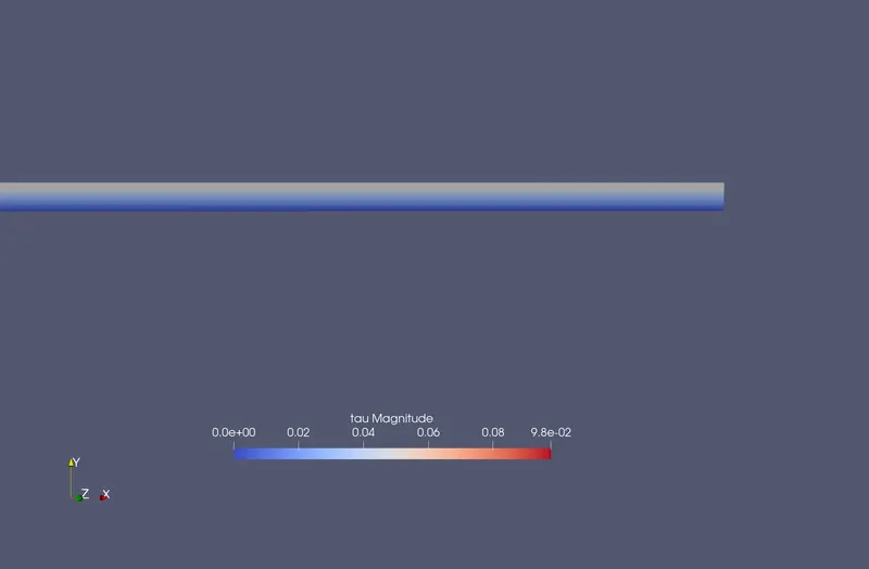
Plots related to shear stress:
a. Numerical shear stress:
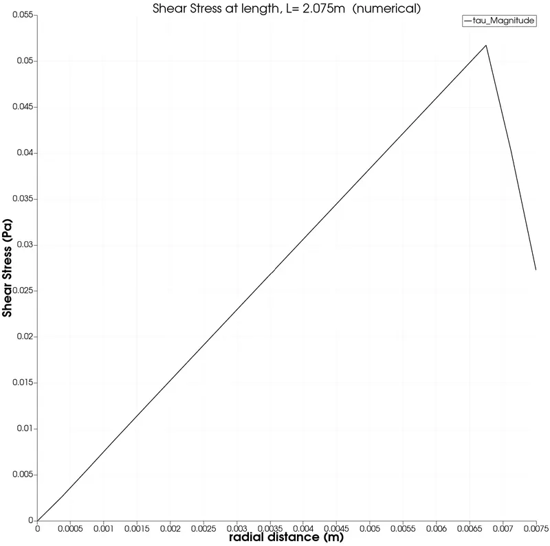
b. Comparison with analytical shear stress:
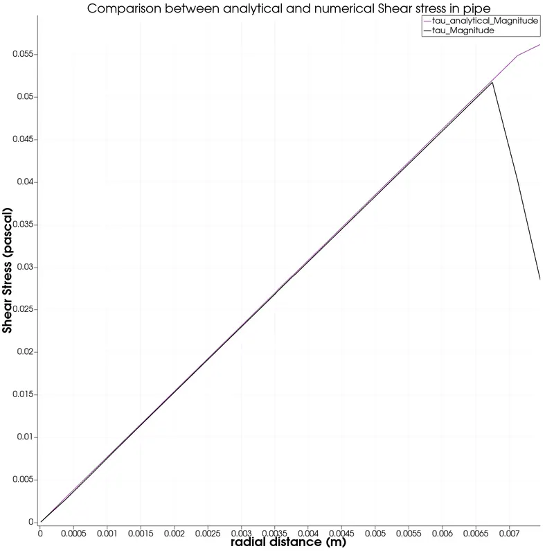
3. Pressure drop at the fully developed flow:
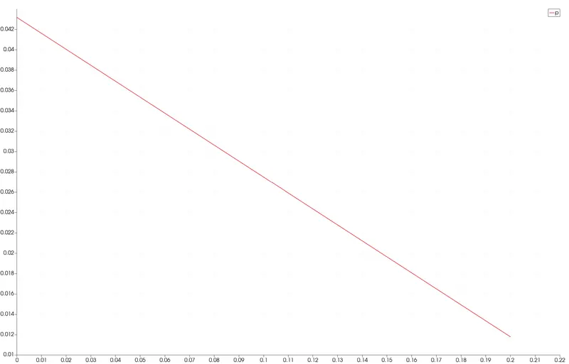
3. Comparison between Analytical and numerical for Velocity, Shear stress and pressure drop:
| Variable | Numerical | Analytical | Difference |
| Velocity (m/s) | 0.2197 | 0.248 | 0.0283 |
| Shear stress (Pa) | 0.0522 | 0.058 | 0.006 |
| Pressure drop (Pa) | 4.0 | 4.7 | 0.7 |