Week 11 - Simulation of Flow through a pipe in OpenFoam
Aim: To simulate an axis-symmetric flow by applying the wedge boundary condition.
Reference Data: The flow is laminar and flows through a constant cross-section pipe at an inlet Reynold's number of 2100. also to validate results with the Hagen- Poiseuille's equations for the fully developed flow. write code in Matlab to automate the generation of blockMeshDict files. The code should take inputs like pipe length, diameter, wedge angle, etc, and output a fully functional blockMeshDict file.
Data Given:
Wedge angle to be less than 5 degrees, Flow is axi-symetrics & Incompressible Laminar flow.
Renolds number - 2100
Expected Results:
- Validate Hydro-dynamic length with the numerical result
- Validate the fully developed flow velocity profile with its analytical profile
- Validate maximum velocity and pressure drop for fully developed flow
- Post-process Shear stress and validate wall shear stress for fully developed flow
Introduction:
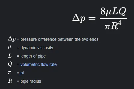
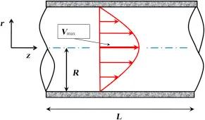
Fluid flow occurs from a higher pressure point to a lower pressure through a pipe (Fluid domain). This can be explained by Hagen-Poiseuille's law which stated that " Pressure drop in an incompressible and Newtonian fluid in laminar flow flowing through a long cylindrical pipe of constant cross-section".
The equation for calculating the Kinematic notation is
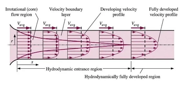
The equation does not hold close to the pipe entrance.
The equation fails in the limit of low viscosity, wide and/or short pipe. Low viscosity or a wide pipe may result in turbulent flow, making it necessary to use more complex models, such as the Darcy–Weisbach equation. The ratio of length to radius of a pipe should be greater than one forty-eighth of the Reynolds number for the Hagen–Poiseuille law to be valid. If the pipe is too short, the Hagen–Poiseuille equation may result in unphysically high flow rates; the flow is bounded by Bernoulli's principle, under less restrictive conditions, by
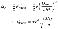
because it is impossible to have negative (absolute) pressure (not to be confused with gauge pressure) in an incompressible flow.
Procedure:
1. Creating Blockmesh dict file using Matlab code. Here pipe diameter is taken as 10mm and the length 1.2 meters.
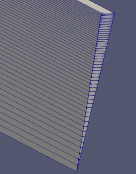
2. Mesh is generated.
3. Inputs are added in OpenFoam's Velocity and Pressure files.
4. Run time and Time steps are added in the ControlDict file of OpenFoam.
5. Simulation is run as we have to take IcoFoam as a solver.
6. Results are viewed in ParaFoam Command, Paraview.
7. Plot results with Velocity for shear stress.
Matlab Program for Blockmesh Dict.
/*---------------------------------*- C++ -*-------------------------------------------------*\
| ========== | |
| \\ / F ield | OpenFOAM: The Open Source CFD Toolbox |
| \\ / O peration | Version: 7 |
| \\ / A nd | Web: www.OpenFOAM.org |
| \\ / M anipulation | |
\*------------------------------------------------------------------------------------------*/
FoamFile
{
version 2.0;
format ascii;
class dictionary;
object blockMeshDict;
}
// * * * * * * * * * * * * * * * * * * * * * * * * * * * * * * * * * * * * * * * * * * * * * \\
convertToMeters 1;
vertices
(
(0.000000 0.000000 0.000000)
(0.000218 0.004995 0.000000)
(-0.000218 0.004995 0.000000)
(0.000000 0.000000 1.200000)
(0.000218 0.004995 1.200000)
(-0.000218 0.004995 1.200000)
);
blocks
(
hex (0 0 1 2 3 3 4 5) (1 50 200) simpleGrading (1 0.5 1)
);
edges
(
arc 1 2 (0.000000 0.005000 0.000000)
arc 4 5 (0.000000 0.005000 1.200000)
);
boundary
(
inflow
{
type patch;
faces
(
(0 0 2 1)
);
}
outflow
{
type patch;
faces
(
(3 4 5 3)
);
}
front
{
type wedge;
faces
(
(0 1 4 3)
);
}
back
{
type wedge;
faces
(
(3 5 2 0)
);
}
wall
{
type wall;
faces
(
(4 1 2 5)
);
}
axis
{
type empty;
faces
(
(0 3 3 0)
);
}
);
mergePatchPairs
(
);
// ************************************************************************************************************************************************** //
Velocity gradient program
/*--------------------------------*- C++ -*----------------------------------*\
========= |
\\ / F ield | OpenFOAM: The Open Source CFD Toolbox
\\ / O peration | Website: https://openfoam.org
\\ / A nd | Version: 10
\\/ M anipulation |
\*---------------------------------------------------------------------------*/
FoamFile
{
format ascii;
class volVectorField;
object U;
}
// * * * * * * * * * * * * * * * * * * * * * * * * * * * * * * * * * * * * * //
dimensions [0 1 -1 0 0 0 0];
internalField uniform (0 0 0);
boundaryField
{
axis
{
type empty;
}
inlet
{
type fixedValue;
value uniform (0.19 0 0);
}
topwall
{
type noSlip;
}
outlet
{
type zeroGradient;
}
front
{
type symmetry;
}
back
{
type symmetry;
}
}
// ************************************************************************* //
Pressure gradient program
/*--------------------------------*- C++ -*----------------------------------*\
========= |
\\ / F ield | OpenFOAM: The Open Source CFD Toolbox
\\ / O peration | Website: https://openfoam.org
\\ / A nd | Version: 10
\\/ M anipulation |
\*---------------------------------------------------------------------------*/
FoamFile
{
format ascii;
class volScalarField;
object p;
}
// * * * * * * * * * * * * * * * * * * * * * * * * * * * * * * * * * * * * * //
dimensions [0 2 -2 0 0 0 0];
internalField uniform 0;
boundaryField
{
axis
{
type empty;
}
inlet
{
type zeroGradient;
}
topwall
{
type zeroGradient;
}
outlet
{
type fixedValue;
value uniform 0;
}
front
{
type symmetry;
}
back
{
type symmetry;
}
}
// ************************************************************************* //
Controldict program
/*--------------------------------*- C++ -*----------------------------------*\
========= |
\\ / F ield | OpenFOAM: The Open Source CFD Toolbox
\\ / O peration | Website: https://openfoam.org
\\ / A nd | Version: 10
\\/ M anipulation |
\*---------------------------------------------------------------------------*/
FoamFile
{
format ascii;
class dictionary;
location "system";
object controlDict;
}
// * * * * * * * * * * * * * * * * * * * * * * * * * * * * * * * * * * * * * //
application icoFoam;
startFrom latestTime;
startTime 0;
stopAt endTime;
endTime 50;
deltaT 0.01;
writeControl timeStep;
writeInterval 20;
purgeWrite 0;
writeFormat ascii;
writePrecision 6;
writeCompression off;
timeFormat general;
timePrecision 6;
runTimeModifiable true;
// ************************************************************************* //
Mesh file

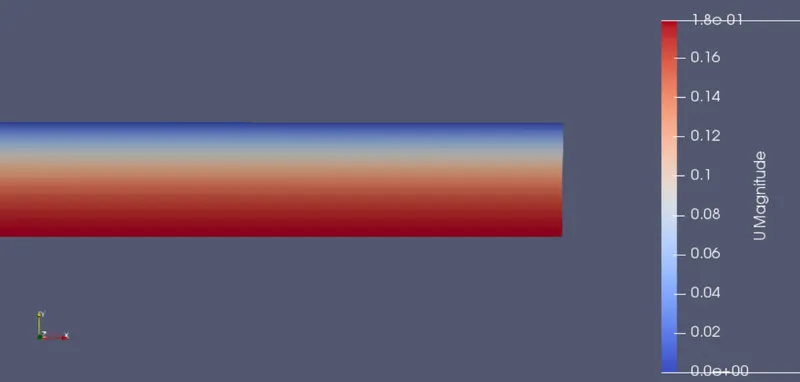
Velocity profile @ 0.1 meters fully developed.
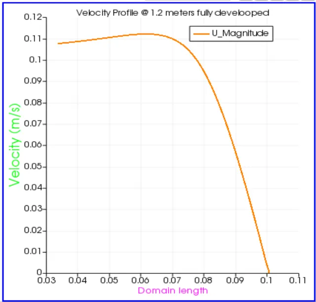
Velocity profile @ 0.5 meters fully developed.
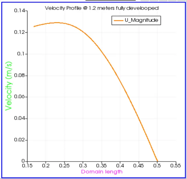
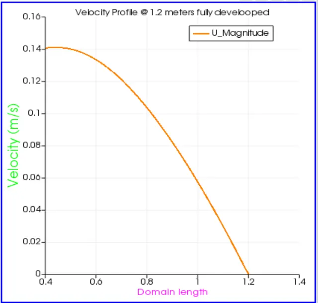
Velocity profile @ 1.2 meters fully developed.
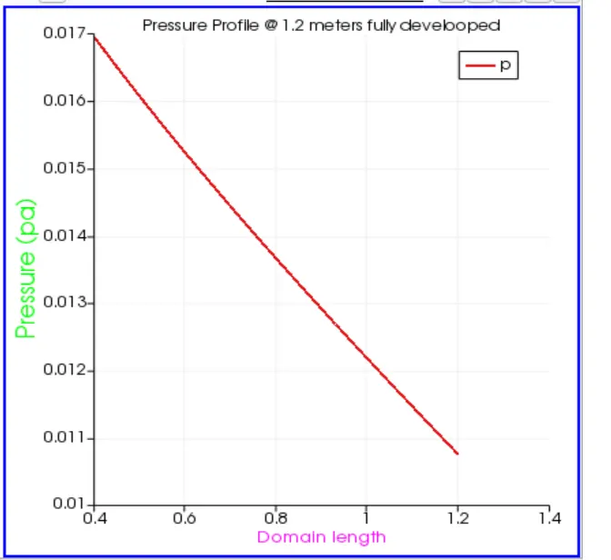
Pressure Profile @1.2 meters fully developed condition.
Conclusion:
1. Simulation was carried out for a wedge angle of 5 degrees. results did not wary with the change in wedge angle to 4 and 3 degrees.
2. Parabolic profile is achieved at the center of the pipe.
3. Velocity is more at the center of the pipe due to the frictional shear stress on the inner side of the pipe.
4. Pressure drop calculated Analytically and Numerically with not much difference.
5. Share stress plot shows stress is minimal at the center of the pipe and maximum at pipe walls.