Simulation of Flow through a pipe in OpenFoam
Simulation of Flow through a pipe in OpenFoam
OBJECTIVE
To simulate an axi-symmetric flow by applying the wedge boundary condition by conducting a transient or steady state simulation and you will validate your results with the Hagen- Poiseuille's equations for the fully developed flow.. The flow is laminar and flows through a constant cross-section pipe at an inlet Reynold's number of 2100.
THEORY
Hagen–Poiseuille equation, also known as the Hagen–Poiseuille law, Poiseuille law or Poiseuille equation, is a physical law that gives the pressure drop in an incompressible and Newtonian fluid in laminar flow flowing through a long cylindrical pipe of constant cross section.
Assumptions:
- The fluid is incompressible and Newtonian
- Laminar flow occurs through a pipe of constant circular cross-section that is substantially longer than its diameter
- There is no acceleration of fluid in the pipe.
Entrance region and Fully Developed region for a Laminar Flow.
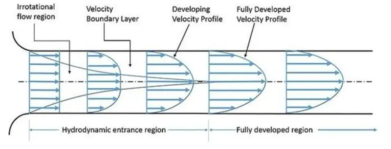
figure 1: Hydrodynamic Entrance region and Fully Developed region
Hydrodynamic entrance region is defined as the area of the pipe, where the fluid entering the pipe developes a velocity profile due to viscous forces propagating from the interior walls.
The region of flow where the viscous and velocity effects changes suddenly is called boundary layer and it separates the flow into two regions-irrotational flow layer and boundary layer region.
When the flow reaches the mid section, velocity profile will be fully developed, and this particular length from the inlet is called as Hydrodynamic entrance length.
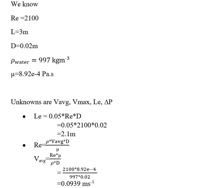
It is calculated as Le=0.05*Re*D
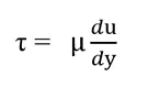
Shear stress is directly proportinal to the velocity gradient and is calculated as
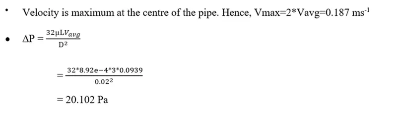
CALCULATIONS
CODE
Writing code in matlab with an objective to create the blockMesh.
clear all
close all
clc
%inputs
Re=2100; %reynolds number
theta=5; %wedge angle
D=0.02; %pipe diameter
R=D/2;
L=3; %length
rho=997; %density of water
mu=8.92e-4;%dynamic viscosity of water
%finding the unknowns
Le=0.05*Re*D; %hydrodynamic entrance length
Vavg=(Re*mu)/(rho*D); %average velocity
Vmax=2*Vavg;
dP= 32*mu*L*Vavg/D^2;%pressure drop-dynamic
dP_k=dP/rho; %pressure drop-kinematic
%number of mesh cells
nx=200;
ny=20;
nz=1;
%mesh grading
gx=1;
gy=0.2;
gz=1;
%vertices of the wedge
v0=[0 0 0];
v1=[0 R*cosd(theta/2) R*sind(theta/2) ];
v2=[0 R*cosd(theta/2) -R*sind(theta/2)];
v3=[L 0 0];
v4=[L R*cosd(theta/2) R*sind(theta/2)];
v5=[L R*cosd(theta/2) -R*sind(theta/2)];
%writing the blockmesh
f1=fopen('blockMeshDict.txt','w');
fprintf(f1,'%s n','/*--------------------------------*- C++ -*----------------------------------*');
fprintf(f1,'%sn','========= |');
fprintf(f1,'%sn',' / F ield | OpenFOAM: The Open Source CFD Toolbox');
fprintf(f1,'%sn',' / O peration | Website: https://openfoam.org');
fprintf(f1,'%sn',' / A nd | Version: 9');
fprintf(f1,'%sn','/ M anipulation |');
fprintf(f1,'%sn','*---------------------------------------------------------------------------*/');
fprintf(f1,'%sn','FoamFile');
fprintf(f1,'%sn','{');
fprintf(f1,'%sn','version 2.0;');
fprintf(f1,'%sn','format ascii;');
fprintf(f1,'%sn','class dictionary;');
fprintf(f1,'%sn','object blockMeshDict;');
fprintf(f1,'%sn','}');
fprintf(f1,'%snn','// * * * * * * * * * * * * * * * * * * * * * * * * * * * * * * * * * * * * * //');
fprintf(f1,'nnconvertToMeters 1 ;');
fprintf(f1,'nvertices');
fprintf(f1,'n(');
fprintf(f1,'n(%f %f %f)//v0',v0(1),v0(2),v0(3)); %v0
fprintf(f1,'n(%f %f %f)//v1',v1(1),v1(2),v1(3)); %v1
fprintf(f1,'n(%f %f %f)//v2',v2(1),v2(2),v2(3)); %v2
fprintf(f1,'n(%f %f %f)//v3',v3(1),v3(2),v3(3)); %v3
fprintf(f1,'n(%f %f %f)//v4',v4(1),v4(2),v4(3)); %v4
fprintf(f1,'n(%f %f %f)//v5',v5(1),v5(2),v5(3)); %v5
fprintf(f1,'nn);');
fprintf(f1,'nblocks');
fprintf(f1,'%sn','(');
fprintf(f1,'n hex (0 3 5 2 0 3 4 1) (%d %d %d) simpleGrading (%f %f %f)',nx,ny,nz,gx,gy,gz);
fprintf(f1,'nn);');
fprintf(f1,'nedges');
fprintf(f1,'n(');
fprintf(f1,'narc 1 2 (%f %f %f)',0,R,0);
fprintf(f1,'narc 4 5 (%f %f %f)',L,R,0);
fprintf(f1,'nn);');
fprintf(f1,'nboundary');
fprintf(f1,'n(');
fprintf(f1,'n inlet');
fprintf(f1,'n {');
fprintf(f1,'n type patch;');
fprintf(f1,'n faces');
fprintf(f1,'n (');
fprintf(f1,'n (2 0 0 1) //0 and 0 are squeezed into a single point');
fprintf(f1,'n );');
fprintf(f1,'n }');
fprintf(f1,'n outlet');
fprintf(f1,'n {');
fprintf(f1,'n type patch;');
fprintf(f1,'n faces');
fprintf(f1,'n (');
fprintf(f1,'n (3 5 4 3)');
fprintf(f1,'n );');
fprintf(f1,'n }');
fprintf(f1,'n topwall');
fprintf(f1,'n {');
fprintf(f1,'n type wall;');
fprintf(f1,'n faces');
fprintf(f1,'n (');
fprintf(f1,'n (4 5 2 1)');
fprintf(f1,'n );');
fprintf(f1,'n }');
fprintf(f1,'n front');
fprintf(f1,'n {');
fprintf(f1,'n type wedge;');
fprintf(f1,'n faces');
fprintf(f1,'n (');
fprintf(f1,'n (4 1 0 3)');
fprintf(f1,'n );');
fprintf(f1,'n }');
fprintf(f1,'n back');
fprintf(f1,'n {');
fprintf(f1,'n type wedge;');
fprintf(f1,'n faces');
fprintf(f1,'n (');
fprintf(f1,'n (0 2 5 3)');
fprintf(f1,'n );');
fprintf(f1,'n }');
fprintf(f1,'n axis');
fprintf(f1,'n {');
fprintf(f1,'n type empty;');
fprintf(f1,'n faces');
fprintf(f1,'n (');
fprintf(f1,'n (0 3 3 0)');
fprintf(f1,'n );');
fprintf(f1,'n }');
fprintf(f1,'nn);');
fprintf(f1,'nmergePatchPairs');
fprintf(f1,'n(');
fprintf(f1,'nn);');
fprintf(f1,'n// ************************************************************************* //');
When we execute this, we get the following blockMeshdict output.
/*--------------------------------*- C++ -*----------------------------------*
========= |
/ F ield | OpenFOAM: The Open Source CFD Toolbox
/ O peration | Website: https://openfoam.org
/ A nd | Version: 9
/ M anipulation |
*---------------------------------------------------------------------------*/
FoamFile
{
version 2.0;
format ascii;
class dictionary;
object blockMeshDict;
}
// * * * * * * * * * * * * * * * * * * * * * * * * * * * * * * * * * * * * * //
convertToMeters 1;
vertices
(
(0.000000 0.000000 0.000000)//v0
(0.000000 0.009990 0.000436)//v1
(0.000000 0.009990 -0.000436)//v2
(3.000000 0.000000 0.000000)//v3
(3.000000 0.009990 0.000436)//v4
(3.000000 0.009990 -0.000436)//v5
);
blocks
(
hex (0 3 5 2 0 3 4 1) (200 20 1) simpleGrading (1.000000 0.200000 1.000000)
);
edges
(
arc 1 2 (0.000000 0.010000 0.000000)
arc 4 5 (3.000000 0.010000 0.000000)
);
boundary
(
inlet
{
type patch;
faces
(
(2 0 0 1) //0 is squeezed to one point
);
}
outlet
{
type patch;
faces
(
(3 3 5 4)
);
}
topwall
{
type wall;
faces
(
(4 5 2 1)
);
}
front
{
type wedge;
faces
(
(4 1 0 3)
);
}
back
{
type wedge;
faces
(
(0 2 5 3)
);
}
axis
{
type empty;
faces
(
(0 3 3 0)
);
}
);
mergePatchPairs
(
);
// ************************************************************************* //
- controlDict
/*--------------------------------*- C++ -*----------------------------------*
========= |
/ F ield | OpenFOAM: The Open Source CFD Toolbox
/ O peration | Website: https://openfoam.org
/ A nd | Version: 9
/ M anipulation |
*---------------------------------------------------------------------------*/
FoamFile
{
format ascii;
class dictionary;
location "system";
object controlDict;
}
// * * * * * * * * * * * * * * * * * * * * * * * * * * * * * * * * * * * * * //
application icoFoam;
startFrom startTime;
startTime 0;
stopAt endTime;
endTime 10;
deltaT 0.01;
writeControl timeStep;
writeInterval 20;
purgeWrite 0;
writeFormat ascii;
writePrecision 6;
writeCompression off;
timeFormat general;
timePrecision 6;
runTimeModifiable true;
// ************************************************************************* //
- transportProperties
/*--------------------------------*- C++ -*----------------------------------*
========= |
/ F ield | OpenFOAM: The Open Source CFD Toolbox
/ O peration | Website: https://openfoam.org
/ A nd | Version: 9
/ M anipulation |
*---------------------------------------------------------------------------*/
FoamFile
{
format ascii;
class dictionary;
location "constant";
object transportProperties;
}
// * * * * * * * * * * * * * * * * * * * * * * * * * * * * * * * * * * * * * //
nu [0 2 -1 0 0 0 0] 0.894e-6;
// ************************************************************************* //
- velocity
/*--------------------------------*- C++ -*----------------------------------*
========= |
/ F ield | OpenFOAM: The Open Source CFD Toolbox
/ O peration | Website: https://openfoam.org
/ A nd | Version: 9
/ M anipulation |
*---------------------------------------------------------------------------*/
FoamFile
{
format ascii;
class volVectorField;
object U;
}
// * * * * * * * * * * * * * * * * * * * * * * * * * * * * * * * * * * * * * //
dimensions [0 1 -1 0 0 0 0];
internalField uniform (0 0 0);
boundaryField
{
inlet
{
type fixedValue;
value uniform (.0939 0 0);
}
outlet
{
type zeroGradient;
}
topwall
{
type noSlip;
}
front
{
type wedge;
}
back
{
type wedge;
}
axis
{
type empty;
}
}
// ************************************************************************* //
- pressure
/*--------------------------------*- C++ -*----------------------------------*
========= |
/ F ield | OpenFOAM: The Open Source CFD Toolbox
/ O peration | Website: https://openfoam.org
/ A nd | Version: 9
/ M anipulation |
*---------------------------------------------------------------------------*/
FoamFile
{
format ascii;
class volScalarField;
object p;
}
// * * * * * * * * * * * * * * * * * * * * * * * * * * * * * * * * * * * * * //
dimensions [0 2 -2 0 0 0 0];
internalField uniform 0;
boundaryField
{
inlet
{
type zeroGradient;
}
outlet
{
type fixedValue;
value uniform 0.0201624;
}
topwall
{
type zeroGradient;
}
front
{
type wedge;
}
back
{
type wedge;
}
axis
{
type empty;
}
}
// ************************************************************************* //
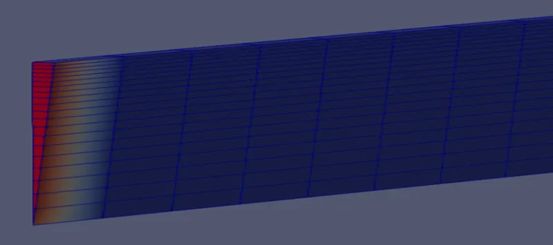
figure 2: Mesh diagram with finer cells towards the boundary(top wall)
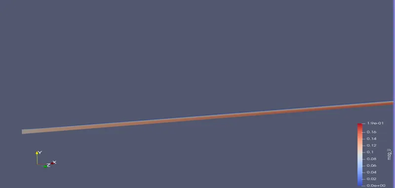
figure 3: Velocity contour plot at the end of final time step
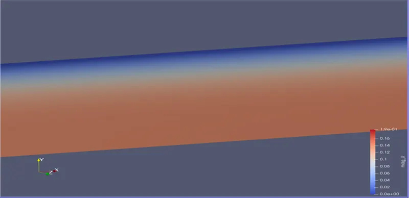
figure 4:Velocity contour plot of a region at the end of final time step
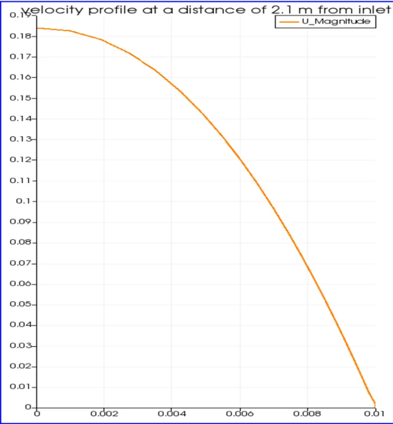
figure 5: velocity profile at the hydrodynamic entrance length

figure 6: velocity profile at a point within the hydrodynamic entrance length
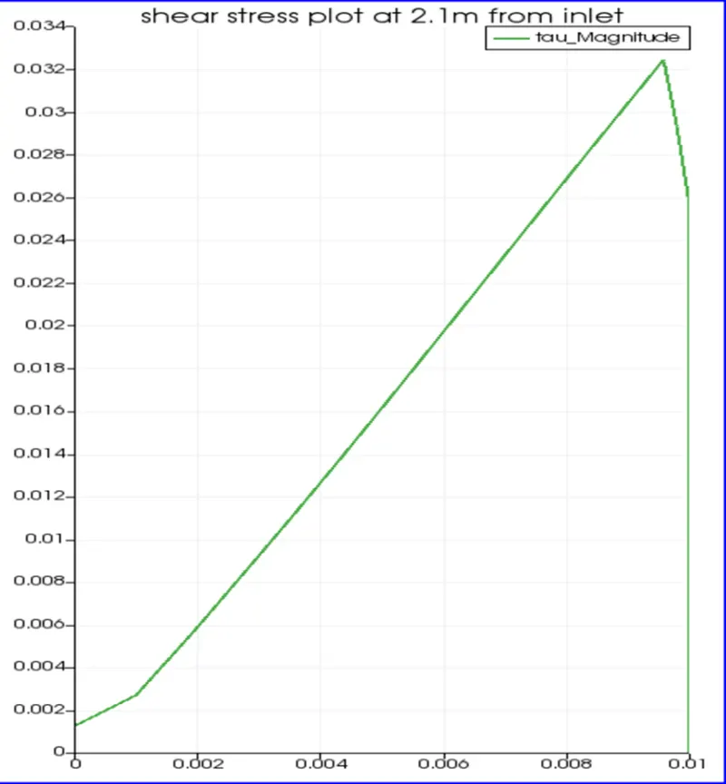
figure 7:Shear stress plot at the hydrodynamic entrance length
CONCLUSION
- It is observed that the hydrodynamic length is 2.1 m, and the velocity profile developes upto this, and does not undergo further development (remains constant).
- The maximum velocity is obtained at the centre of the pipe, 0.187 m/s, which clearly fits the analytical value.
- The shear stress plot obtained after post-processing explains the fact that shear stress is maximum at the walls and zero at the centre. This is because, shear stress increases with friction and hence giving maximum velocity at the centre.