Week 11 - Simulation of Flow through a pipe in OpenFoam
OBJECTIVE: To simulate an axis-symmetric flow by applying the wedge boundary condition. The flow is laminar and flows through a constant cross-section pipe at an Inlet Reynold's number of 2100 and validate your results with the Hagen- Poiseuille's equations for the fully developed flow.
Specification of Problem:
1. Reynold's Number as given: 2100
2. Fluid: Water at 25 degrees Celcius
3. Diameter of Pipe: 0.02m
4. Entry Length `L_(entry) = 0.06*Re*D ==> L_(entry) = 2.52m`
5. Total Length of Pipe = 2.7m
6. Density `rho` = `997kgm^-3`
7. Dynamic Viscosity `mu` = `0.89 * 10^-3 Pa.s`
8. Kinematic Viscosity `nu` = `0.897 * 10^-6 m^2s^-1`
Analytical Solution:
1. Average velocity `V_(avg)` = `(R*mu)/(rho*D)` = 0.03973`ms^-1`
2. Maximum velocity `V_(max) = 2*V_(avg)`= 0.1875 `ms^-1`
3. Pressure Drop `DeltaP = (32*mu*L*V_(avg)*)/D^2 =` 18.01 Pa
4. Kinematic pressure Drop `Deltap_k = (DeltaP)/rho` = 0.018072m
MATLAB Code to generate blockMeshDict file for OpenFOAM
close all
clear all
clc

%data for analysis of Flow

Re=2100; %Reynold's no.

rho    = input("enter fluid density: ") ;
mu     = input("enter fluid dynamic viscosity: ") ;
d      = input("enter diameter of  pipe in meters: ") ;
theta  = input("enter wedge angle for pipe: ") ;

%Entry Length of pipe
Le = d*(0.06*Re);

%Actual Length of pipe
L  = 0.5 + Le ;

%Boundary Conditions
v_avg  = Re*mu/(rho*d) ;
v_max  = 2*v_avg ;
dp     = 32*v_avg*mu*L*(d)^-2 ;
nu     = mu/rho ;

%Wedge geometry vertices
v0 = [0 0 0] ;
v1 = [0 d/2*cosd(theta/2) -d/2*sind(theta/2)] ;
v2 = [0 d/2*cosd(theta/2)  d/2*sind(theta/2)] ;
v3 = [1 0 0] ;
v4 = [1 d/2*cosd(theta/2) -d/2*sind(theta/2)] ;
v5 = [1 d/2*cosd(theta/2)  d/2*sind(theta/2)] ;

arc1 = [0.0 d/2 0.0] ;
arc2 = [1.0 d/2 0.0] ;

%Grid

x  = input("Enter the no. of grid points along x-axis: ") ;
y  = input("Enter the no. of grid points along y-axis: ") ;
z  = input("Enter the no. of grid points along z-axis: ") ;
xx = input("Enter the grading along x-axis: ") ;
yy = input("Enter the grading along y-axis: ") ;
zz = input("Enter the grading along z-axis: ") ;

n = input("Enter conversion unit value: ") ;


 line1 = '|/*----------------------c++------------------------------------------------------------------------*\|';
 line2 = '|         ========                                                                                    |';
 line3 = '|         \      /       F ield        | OpenFoam: The Open Source CFD Toolbox                        |';
 line4 = '|          \    /        O peration    | Website: https://openfoam.org                                |';
 line5 = '|           \  /         A nd          | Version: 6                                                   |';
 line6 = '|            \/          M anipulation |                                                              ';
 line7 = '|\*-------------------------------------------------------------------------------------------------*/|';
 line8 = 'Foamfile ';
 line9 = '{' ;

%%Creating Blockmesh Dictionary file using File Parsing%%

f1 = fopen("blockMeshDict.txt",'w');
fprintf(f1,'%s\n',line1);
fprintf(f1,'%s\n',line2);
fprintf(f1,'%s\n',line3);
fprintf(f1,'%s\n',line4);
fprintf(f1,'%s\n',line5);
fprintf(f1,'%s\n',line6);
fprintf(f1,'%s\n',line7);
fprintf(f1,'\n');
fprintf(f1,'%s\n',line8);
fprintf(f1,'%s\n\n',line9);

fprintf(f1,'%16s %10s \n','version','   2.0;     ');
fprintf(f1,'%16s %10s \n','format','   ascii;     ');
fprintf(f1,'%16s %10s \n','class','   dictionary;     ');
fprintf(f1,'%16s %10s \n','object','   blockMeshDict;     ');
fprintf(f1,'\n } \n \n');
fprintf(f1,'//***********************************************//\n');
fprintf(f1,'convertToMeters %d;\n \n',n);

%Defining Vertices of Geometry

fprintf(f1,'\t\t vertices \n');
fprintf(f1,'\t\t(\n');
fprintf(f1,'\t\t\t(%f %f %f)\n',v0);
fprintf(f1,'\t\t\t(%f %f %f)\n',v1);
fprintf(f1,'\t\t\t(%f %f %f)\n',v2);
fprintf(f1,'\t\t\t(%f %f %f)\n',v3);
fprintf(f1,'\t\t\t(%f %f %f)\n',v4);
fprintf(f1,'\t\t\t(%f %f %f)\n',v5);
fprintf(f1,'\t\t);\n\n');
fprintf(f1,'\t\tblocks;\n');
fprintf(f1,'\t\t(\n');
fprintf(f1,'\t\t\t hex(0 1 2 0 3 4 5 3)) (%d %d %d) simpleGrading (%d %d %d)\n\t\t;\n\n',x,y,z,xx,yy,zz);

%Defining Sides of Geometry

%Edge of Pipe
fprintf(f1,'\t\tedges\n');
fprintf(f1,'\t\t(\n');
fprintf(f1,'\t\t\tarc 1 2 (%f %f %f) \n',arc1);
fprintf(f1,'\t\t\tarc 4 5 (%f %f %f) \n',arc2);
fprintf(f1,'\t\t);\n\n');

%Defining boundary of Pipe
fprintf(f1,'\t\tboundary\t\t(\n');

%Inlet section
fprintf(f1,'%16s\n','inlet');
fprintf(f1,'%10s\n','{');
fprintf(f1,'%25s\n','type patch');
fprintf(f1,'%19s\n','faces');
fprintf(f1,'%15s\n','(');
fprintf(f1,'%28s\n','(0 1 2 0)');
fprintf(f1,'%16s\n',');');
fprintf(f1,'%10s\n','}');
fprintf(f1,'\n');


%Outlet section
fprintf(f1,'%15s\n','outlet');
fprintf(f1,'%10s\n','{');
fprintf(f1,'%25s\n','type patch');
fprintf(f1,'%19s\n','faces');
fprintf(f1,'%15s\n','(');
fprintf(f1,'%28s\n','(3 4 5 3)');
fprintf(f1,'%16s\n',');');
fprintf(f1,'%10s\n','}');
fprintf(f1,'\n');


%Front Side of Pipe

fprintf(f1,'%13s\n','Front');
fprintf(f1,'%10s\n','{');
fprintf(f1,'%25s\n','type wedge');
fprintf(f1,'%19s\n','faces');
fprintf(f1,'%15s\n','(');
fprintf(f1,'%28s\n','(0 2 5 3)');
fprintf(f1,'%16s\n',');');
fprintf(f1,'%10s\n','}');
fprintf(f1,'\n');


%Back Side of Pipe

fprintf(f1,'%13s\n','Back');
fprintf(f1,'%10s\n','{');
fprintf(f1,'%25s\n','type wedge');
fprintf(f1,'%19s\n','faces');
fprintf(f1,'%15s\n','(');
fprintf(f1,'%28s\n','(0 2 5 3)');
fprintf(f1,'%16s\n',');');
fprintf(f1,'%10s\n','}');
fprintf(f1,'\n');

%Top Side of Pipe

fprintf(f1,'%12s\n','Top');
fprintf(f1,'%10s\n','{');
fprintf(f1,'%24s\n','type patch');
fprintf(f1,'%19s\n','faces');
fprintf(f1,'%15s\n','(');
fprintf(f1,'%28s\n','(1 2 5 4)');
fprintf(f1,'%16s\n',');');
fprintf(f1,'%10s\n','}');
fprintf(f1,'\n');


%Axis of Pipe

fprintf(f1,'%13s\n','Axis');
fprintf(f1,'%10s\n','{');
fprintf(f1,'%25s\n','type empty');
fprintf(f1,'%19s\n','faces');
fprintf(f1,'%15s\n','(');
fprintf(f1,'%28s\n','(0 3 3 0)');
fprintf(f1,'%16s\n',');');
fprintf(f1,'%10s\n','}');
fprintf(f1,'%5s\n',');');
fprintf(f1,'\n');


fprintf(f1,'%20s\n','mergePatchPairs');
fprintf(f1,'%6s\n','(');
fprintf(f1,'%7s\n',');');
fclose(f1);


%%%%%%%%%%%%%%%%%%%%%% COMPLETED %%%%%%%%%%%%%%%%%%%%%%%%%%%%%%%%
**************************************************************************************
The generated blockMeshDict File generated from above:
|/*----------------------c++------------------------------------------------------------------------*\|
|         ========                                                                                    |
|         \      /       F ield        | OpenFoam: The Open Source CFD Toolbox                        |
|          \    /        O peration    | Website: https://openfoam.org                                |
|           \  /         A nd          | Version: 6                                                   |
|            \/          M anipulation |
|\*-------------------------------------------------------------------------------------------------*/|

Foamfile
{

         version    2.0;
          format    ascii;
           class    dictionary;
          object    blockMeshDict;

 }

//***********************************************//
convertToMeters 1;

		 vertices
		(
			(0.000000 0.000000 0.000000)
			(0.000000 0.999848 -0.017452)
			(0.000000 0.999848 0.017452)
			(1.000000 0.000000 0.000000)
			(1.000000 0.999848 -0.017452)
			(1.000000 0.999848 0.017452)
		);

		blocks;
		(
			 hex(0 1 2 0 3 4 5 3)) (100 100 100) simpleGrading (1 1 1)
		;

		edges
		(
			arc 1 2 (0.000000 1.000000 0.000000)
			arc 4 5 (1.000000 1.000000 0.000000)
		);

		boundary		(
           inlet
         {
               type patch
              faces
              (
                   (0 1 2 0)
              );
         }

         outlet
         {
               type patch
              faces
              (
                   (3 4 5 3)
              );
         }

        Front
         {
               type wedge
              faces
              (
                   (0 2 5 3)
              );
         }

         Back
         {
               type wedge
              faces
              (
                   (0 2 5 3)
              );
         }

         Top
         {
              type patch
              faces
              (
                   (1 2 5 4)
              );
         }

         Axis
         {
               type empty
              faces
              (
                   (0 3 3 0)
              );
         }
   );

     mergePatchPairs
     (
     );
----------------------------------------------------------------------------------------------------------------------------------
Pressure Boundary Conditions:
/*--------------------------------*- C++ -*----------------------------------*\
  =========                 |
  \\      /  F ield         | OpenFOAM: The Open Source CFD Toolbox
   \\    /   O peration     | Website:  https://openfoam.org
    \\  /    A nd           | Version:  8
     \\/     M anipulation  |
\*---------------------------------------------------------------------------*/
FoamFile
{
    version     2.0;
    format      ascii;
    class       volScalarField;
    object      p;
}
// * * * * * * * * * * * * * * * * * * * * * * * * * * * * * * * * * * * * * //

dimensions      [0 2 -2 0 0 0 0];

internalField   uniform 0;

boundaryField
{
    inlet
    {
        type            zeroGradient;
    }

    outlet
    {
        type            fixedValue;
        value	uniform 0;
    }

    Top
    {
        type            zeroGradient;
    }

    Front
    {
        type            wedge;
    }
    Back
    {
        type            wedge;
    }
    Axis
    {
        type            empty;
    }

}

// ************************************************************************* //
----------------------------------------------------------------------------------------------------------------------------------
Velocity Boundary Conditions:
/*--------------------------------*- C++ -*----------------------------------*\
  =========                 |
  \\      /  F ield         | OpenFOAM: The Open Source CFD Toolbox
   \\    /   O peration     | Website:  https://openfoam.org
    \\  /    A nd           | Version:  8
     \\/     M anipulation  |
\*---------------------------------------------------------------------------*/
FoamFile
{
    version     2.0;
    format      ascii;
    class       volVectorField;
    object      U;
}
// * * * * * * * * * * * * * * * * * * * * * * * * * * * * * * * * * * * * * //

dimensions      [0 1 -1 0 0 0 0];

internalField   uniform (0 0 0);

boundaryField
{
    inlet
    {
        type            fixedValue;
        value           uniform (1 0 0);
    }
    outlet
    {
        type            zeroGradient;
    }

    Top
    {
        type            noSlip;
    }

    Front
    {
        type            wedge;
    }
    Back
    {
        type            wedge;
    }

    Axis
    {
        type            empty;
    }

}

// ************************************************************************* //
----------------------------------------------------------------------------------------------------------------------------------
Transport Properties:
/*--------------------------------*- C++ -*----------------------------------*\
  =========                 |
  \\      /  F ield         | OpenFOAM: The Open Source CFD Toolbox
   \\    /   O peration     | Website:  https://openfoam.org
    \\  /    A nd           | Version:  8
     \\/     M anipulation  |
\*---------------------------------------------------------------------------*/
FoamFile
{
    version     2.0;
    format      ascii;
    class       dictionary;
    location    "constant";
    object      transportProperties;
}
// * * * * * * * * * * * * * * * * * * * * * * * * * * * * * * * * * * * * * //

nu              [0 2 -1 0 0 0 0] 0.001;


// ************************************************************************* //
------------------------------------------------------------------------------------------------------------
Mesh Profile
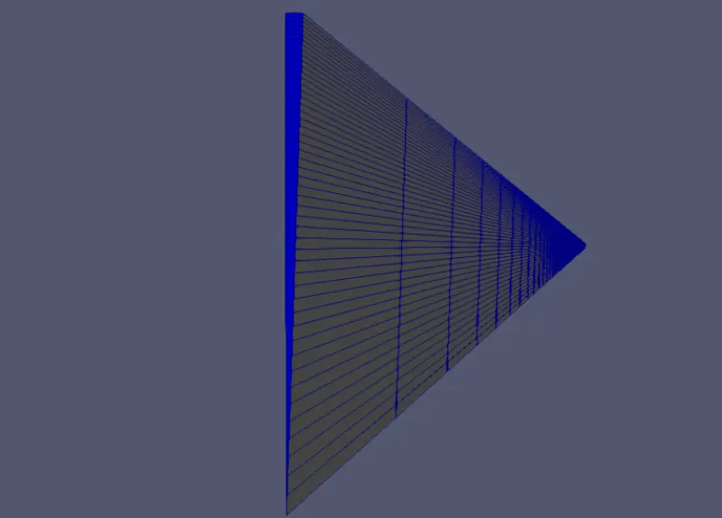
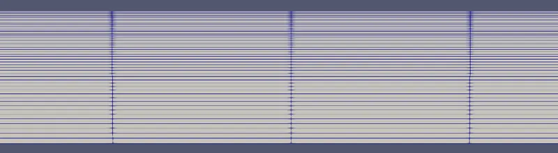
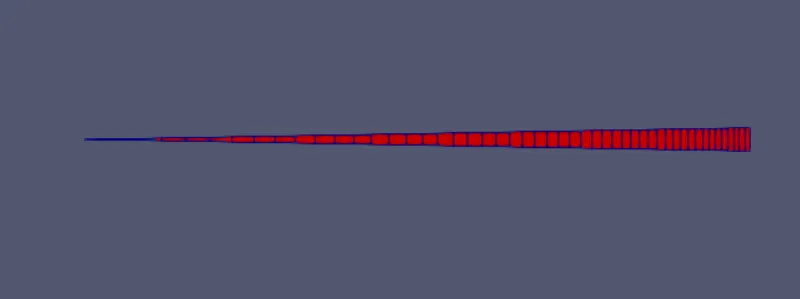
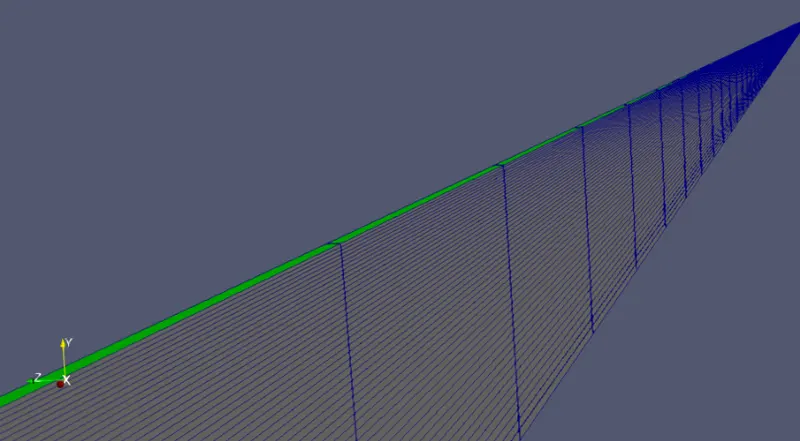
Wedge Boundary Condition:
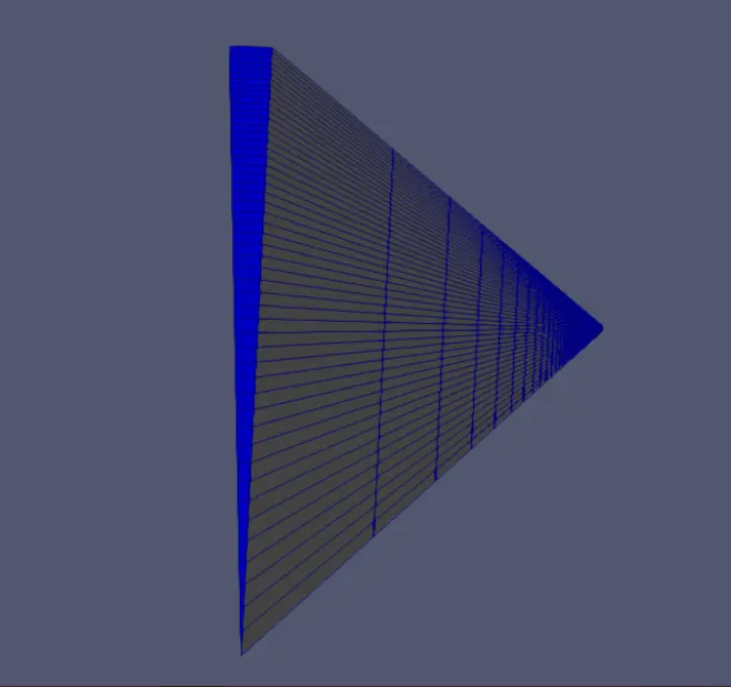
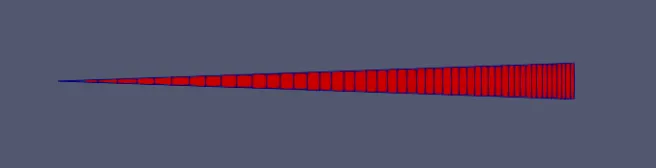
The wedge boundary condition (BC) is used in computational fluid dynamics to define an axisymmetric situation, for eg. cylinder. The model and flow must be axisymmetric along a central line such that all physical variables of the flow have the same value and distribution at a given radius for all angles.
This boundary condition is specified by two planes that must be selected on separate sides of the domain (referred to as front and back) on surfaces running along the axis. It works for 2D simulations only.
Results of Simulation:
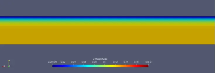
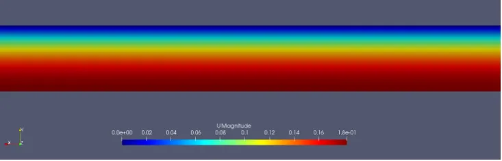
For Wedge Angle of 2 degrees
Velocity Profile at t = 1.25 s
Velocity Profile at t = 25 s
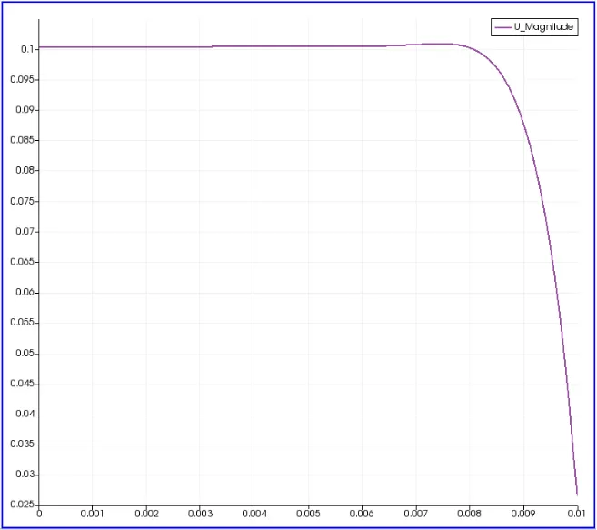
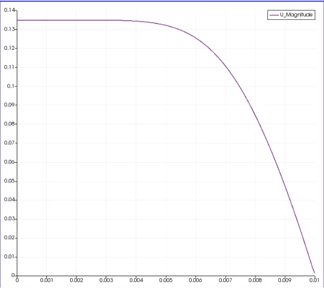
Velocity Profile plots:
At d = 0.01 m from Inlet
At d = 0.2 m from Inlet
At d = 0.5 m from Inlet
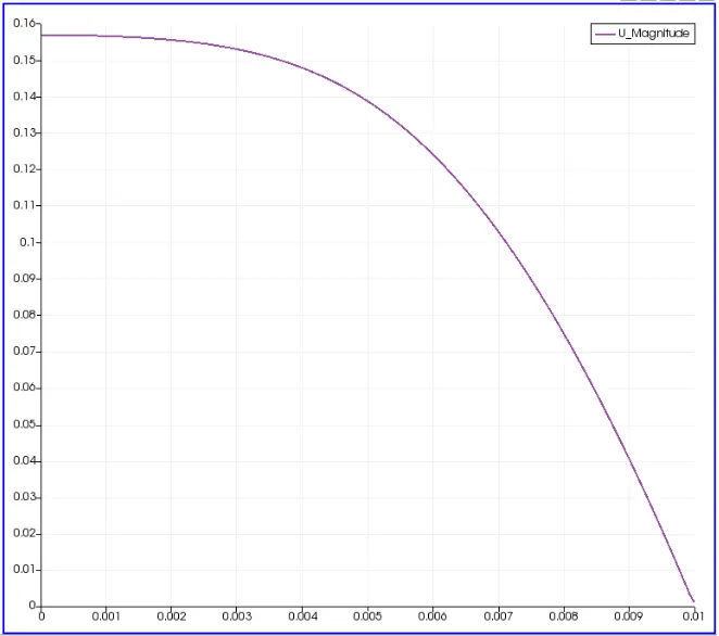
At d = 1.0 m from Inlet
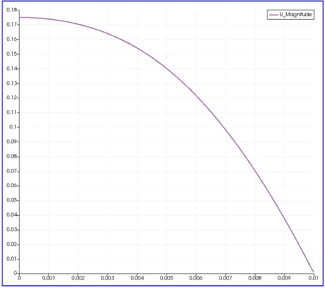
At Entry Length Le = 2.52 m (Analytical Solution)
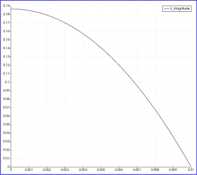
------------------------------------------------------------------------------------------------------------------------------
Velocity Profiles for Wedge Angle = 3 degrees
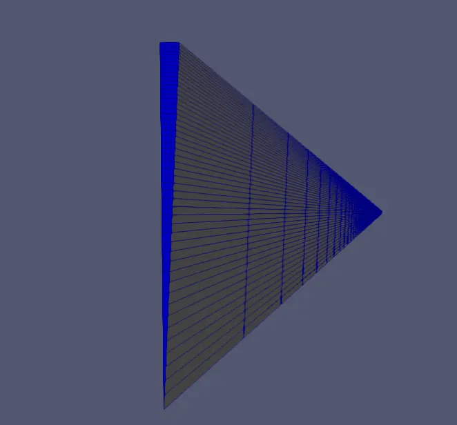
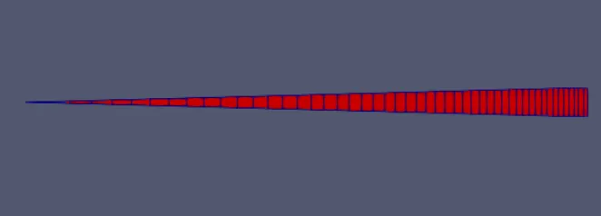
Velocity Contour near Inlet:
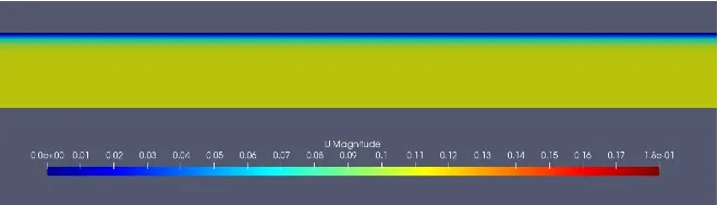
Velocity Contour Fully Developed Flow
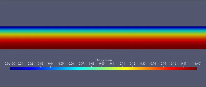
Velocity Plot at d = 0.1 m
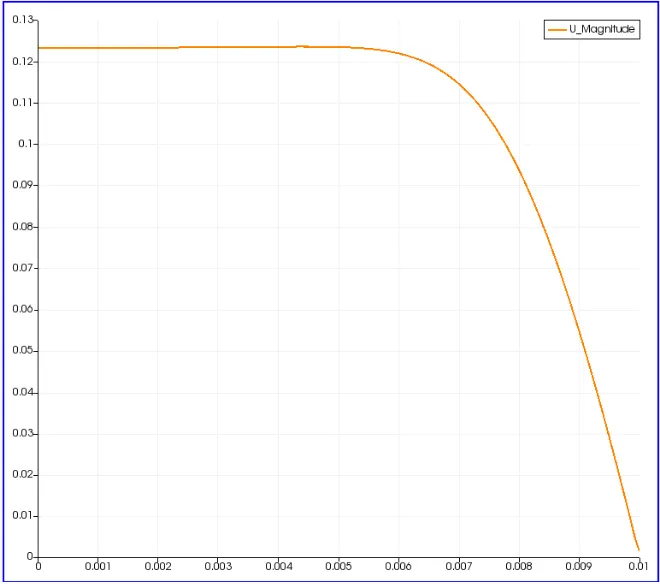
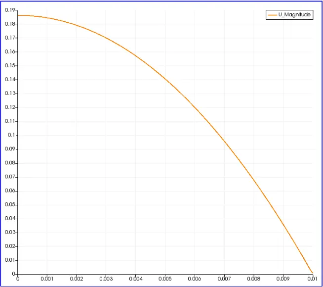
Velocity Plot at d = 2.52 m
-------------------------------------------------------------------------------------------------------------------------------
Wedge Angle = 4 degrees
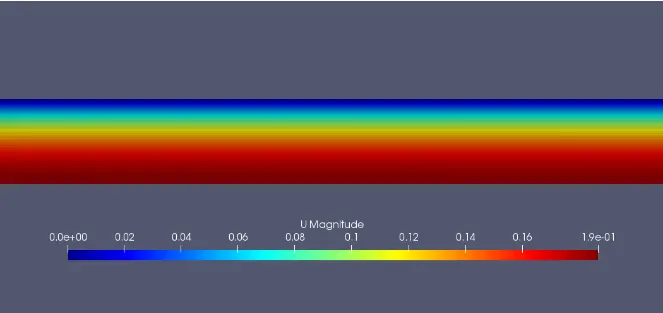
Velocity Contour near Inlet
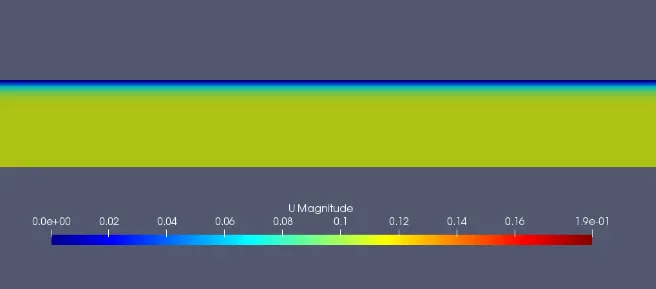
Velocity Contour Fully Developed Flow
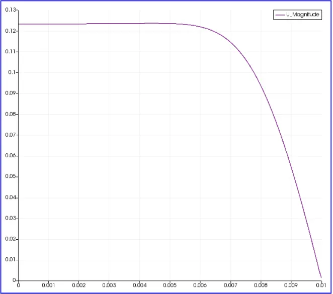
Velocity Plot at d = 0.1 m from Inlet
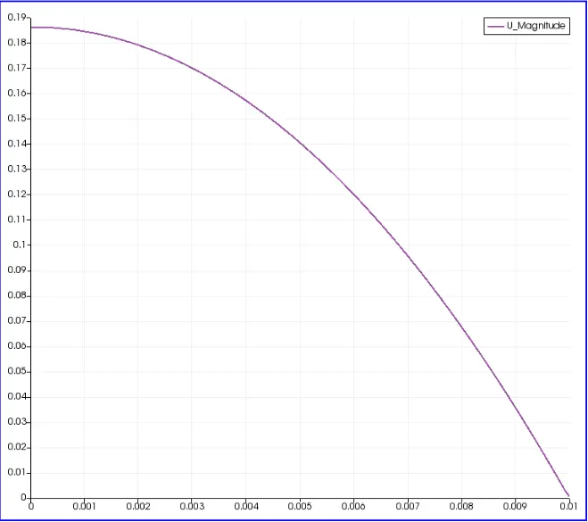
Velocity Plot at d = 2.52 m from Inlet
COMPARISON:
| Wedge Angle (degrees) | Max. Velocity from Simulation (m/s) | Max. Velocity from Simulation (m/s) | Error % |
| 2 | 0.186341 | 0.1875 | 0.6181 |
| 3 | 0.186342 | 0.1875 | 0.6176 |
| 4 | 0.186344 | 0.1875 | 0.6165 |
CONCLUSION:
The Simulation was done and results were studied for different wedge angles and the data was validated using Analytical Solution. The above study shows that a greater wedge angle improves the accuracy of the results. However, the sample size is very small (3) and there is a scope of doing more simulations at different wedge angles to improve the accuracy of results of and conclusion.