Week 11 - Project - A pillar Design with Master Section
Aim- To create an A-pillar from the given Class-A surface and the Master Section. Use the Master Section for the proper thickness and dimensions of the plastic component.
THEORY-
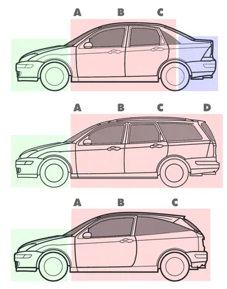
A PILLAR: A-pillars straddle the windshield, B-pillars are in the middle of the passenger compartment (just behind the front doors) and C-pillars are at the rear of the passenger compartment.
MASTER SECTION- A master section in automotive design is a parameterized model of a vehicle body that guides the design requirements for a component.
- Purpose-
- Master sections are created during the Concept Validation and Feasibility Check stages. They help decide the thickness of components, the location and thickness of B side features, and the feasibility of components and their environment.
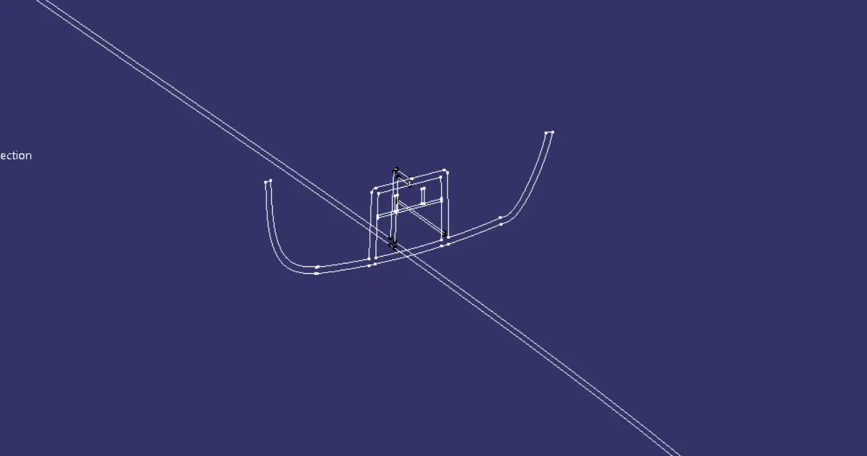
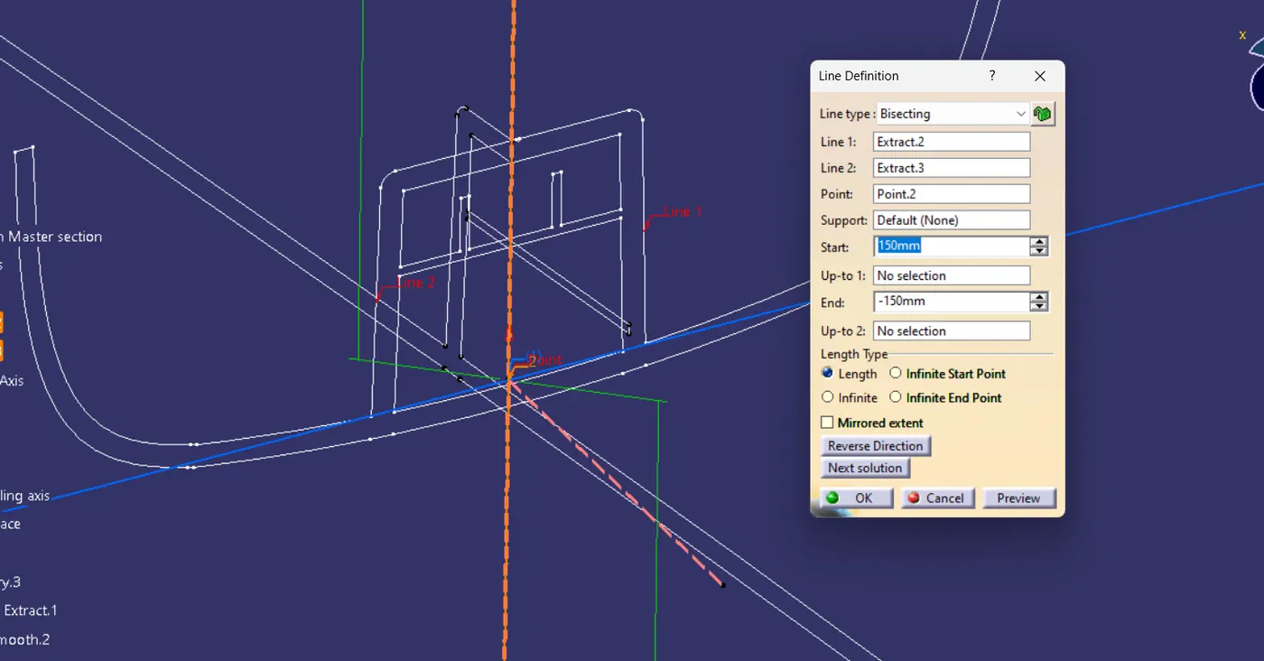
Tooling Axis- For creating the main tooling axis I have used the Bisecting method with the help of the master section of the B-side feature ( Dog House ).
I selected two faces from the dog house's master section and then created a bisecting line. I used the dog house master section to create the tooling axis because the dog house is tooled with the same tooling axis as the entire A-Pillar.
The Side core axis is created using a plane which is created by using the 3 points on the dog house master section and with the line command ( point and direction ).
Class-A Surface and Draft Analysis of the Class-A:-
Class-A is quality checked for any gap between the sub-faces of the entire Class-A. It is checked by either the join command or by boundary command in Catia software.
After creating the main tooling axis the draft analysis is carried out on the Class-A surface using the "feature draft analysis" command in the surface workbench.
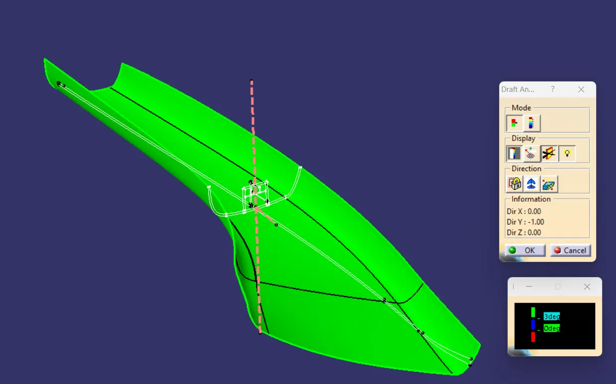
3 degrees is the nominal value for the draft, whereas 0.5 degrees can also be manufactured at ribs.
Some faces of the surface are not clearing the draft. It is seen that the draft over those surfaces has a draft less than the nominal draft value of 3 degrees. So, it is recommended for the class A designer to redesign the class A surface to obtain all the surfaces cleared.
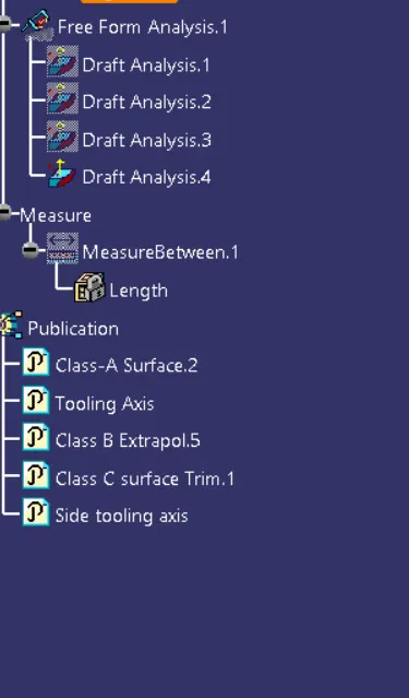
Whatever is used multiple times should be published so that it can be easily accessed whenever needed.
Class-B surface creation-
Class-B surface is behind the class-A surface. It is used to give the thickness of the component on which all the engineering features are placed also called B-side features.
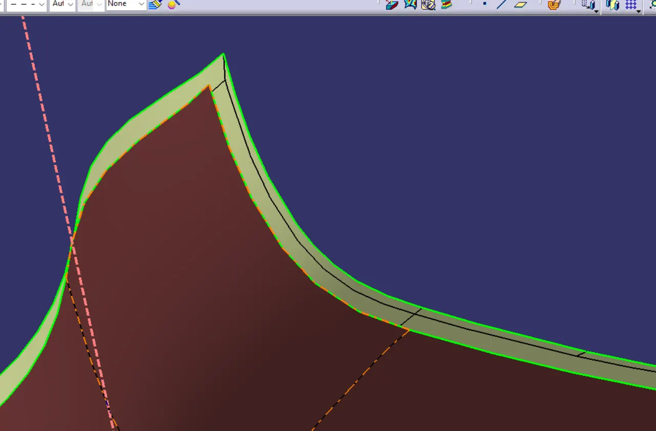
In the above picture, the neutral color of catia is the Class-B surface the brown one is the lass-A surface.
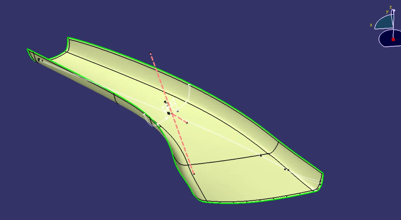
Class-B surface. The thickness of the component is taken from the Master-Section.
Class-C surface creation-
Class Surface is the surface between the class-A and B surfaces it is used to join the class-A and B surfaces together to create a close surface.
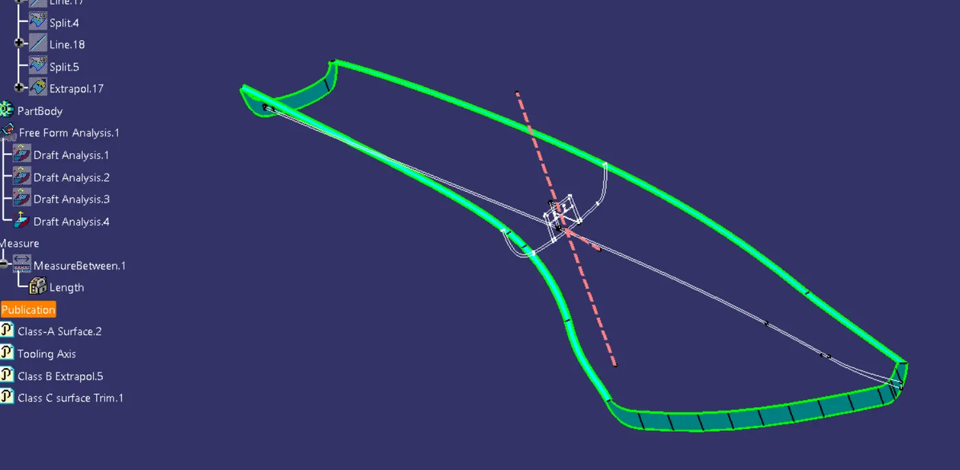
Class A and C trimmed together to create a single surface-
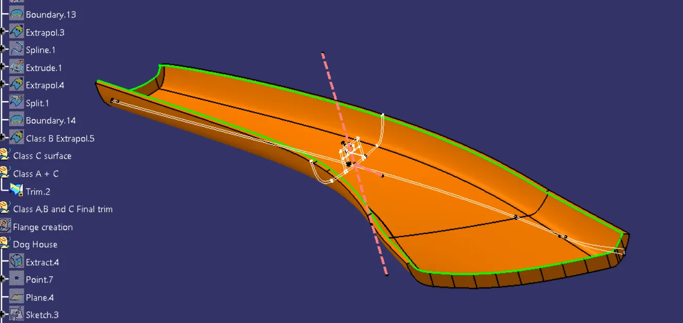
Final Trim class A+B+C surfaces (Closed Surface) -
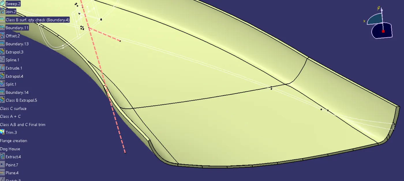
Before creating a solid part a boundary check is done on the closed surface if the boundary command pops up an error of not able to create boundy because it is a closed surface. So it is good to use for creating a solid surface.
A solid part from the closed surface using the closed surface command in part workbench-
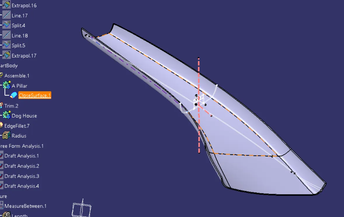
Creation Of Doghouse-
- Doghouse are created by following the design rules.
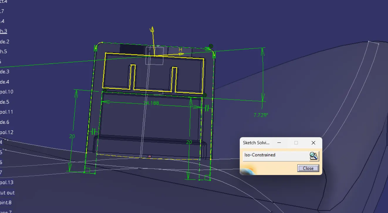
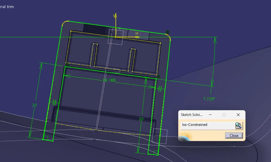
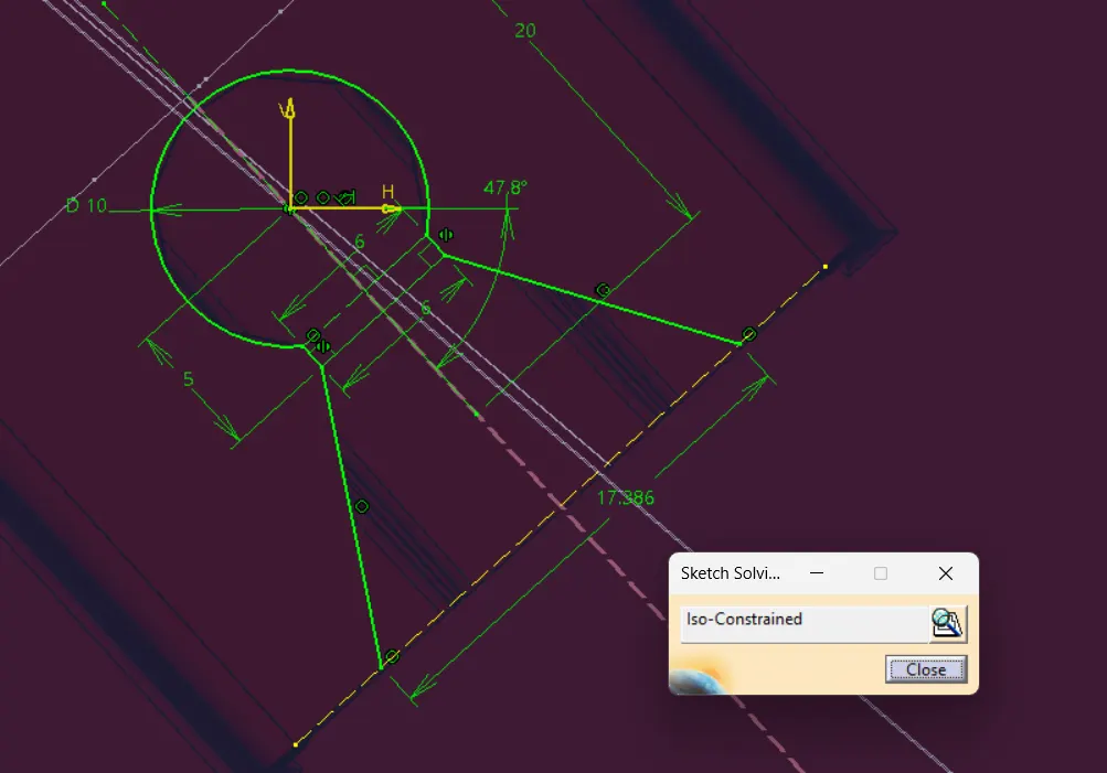
- For this, the sketch is created from the master section provided.
- It is then made to a closed body and made-to-part model.
- Drafts are given for the surfaces as per design rules and proper fillets are also provided.
- As per the given master section, ribs, and supporting features are also added to the doghouse.
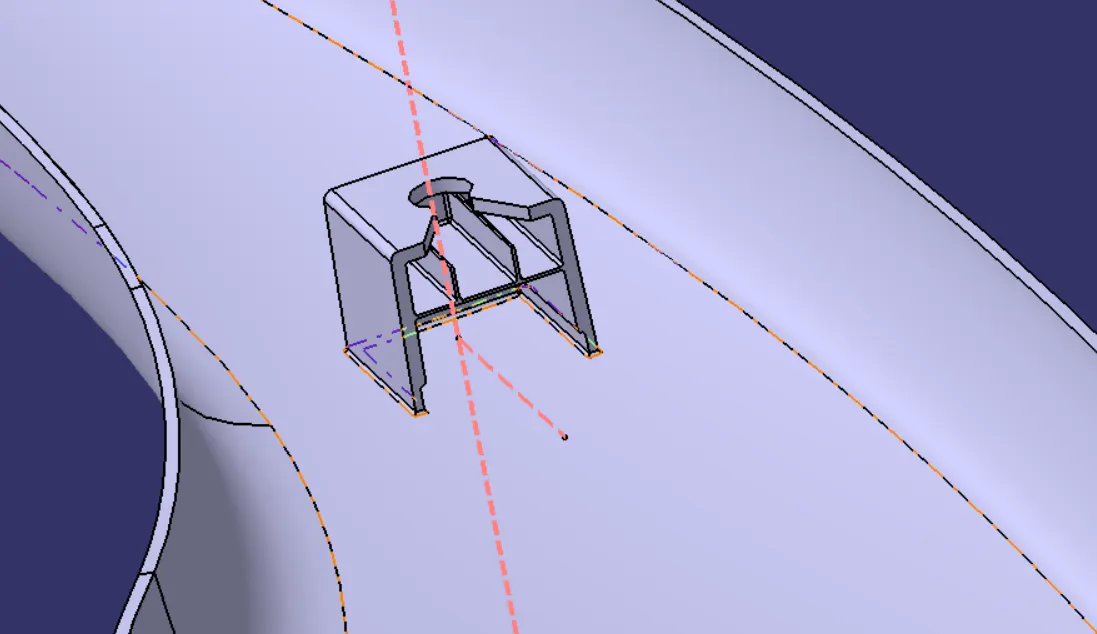
- Then, the doghouse is added to the main body.
All the sketches used are iso-constraint.
To create a sketch a plane is required which is created by using parallel through-point and the sketch is created on this plane.
3D projection of the solid body is used to create the complete and iso-constraint sketches.
The dog house is trimmed with the mail A pillar body-
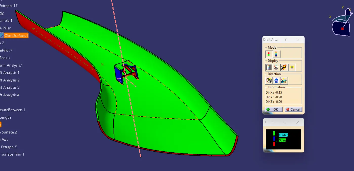
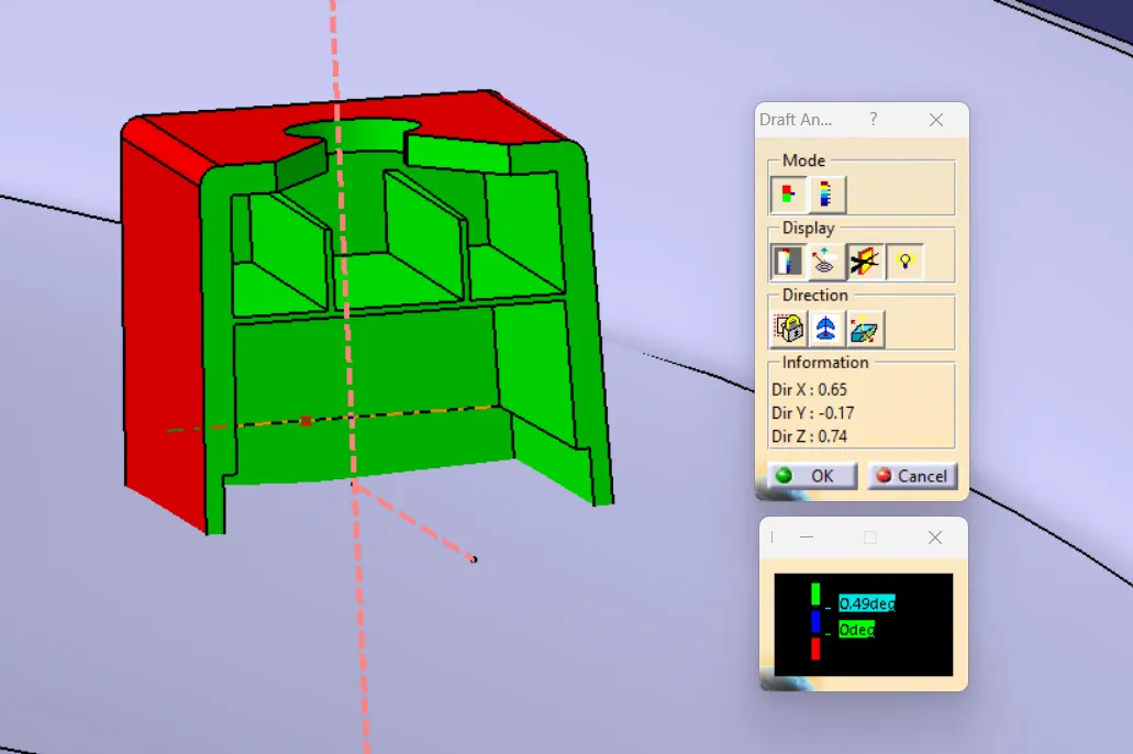
Draft analysis of the entire A-pillar along with the dog house along the main tooling axis-
B-side draft analysis.
the blue color portion is 0.5 degree drafted as per the dog house design rules.
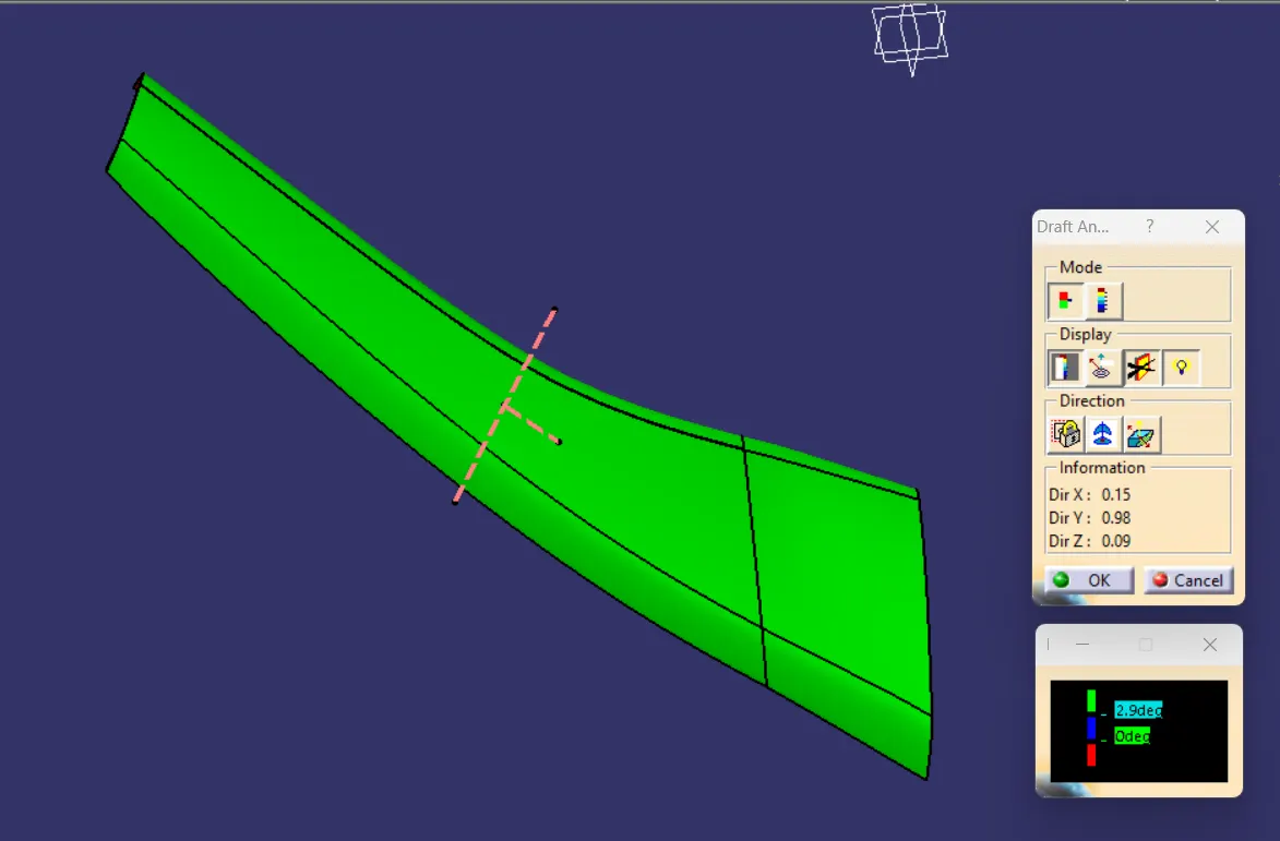
A side draft analysis.
Dog house draft analysis-
Drafted along the side core axis.
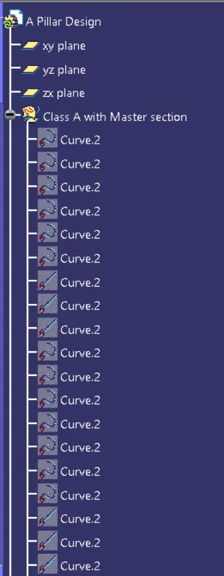
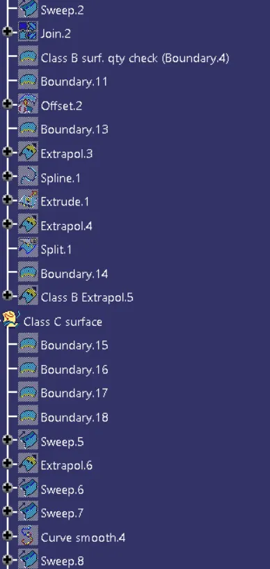
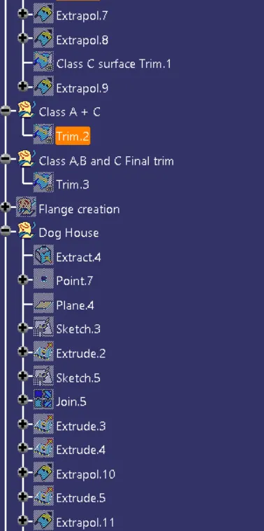
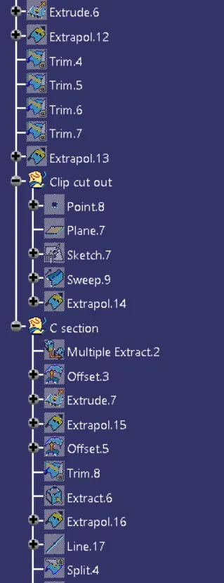
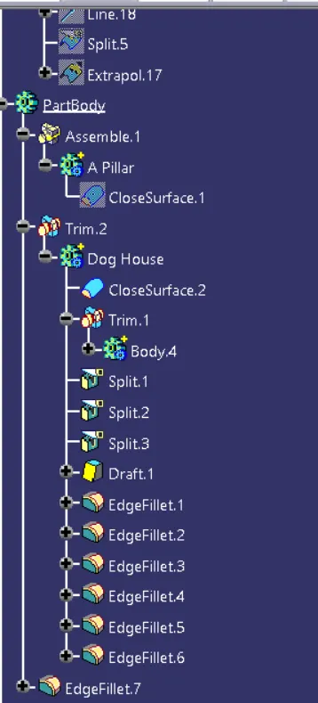
Picture of the Detailed tree structure-
CONCLUSION
- Created Tooling axis
- Created Class B and Class C surface from provided Class A surface.
- Created solid part out of surface modelling.
- Created engineering features from the master section provided.
- Draft analysis of Class A surface and final part is also done.
- Published all the major things.