Week 11 - Project - A pillar Design with Master Section
Aim:To Create a Pillar design with the help of the master section
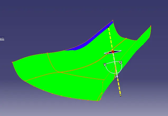
TOOLING AXIS:
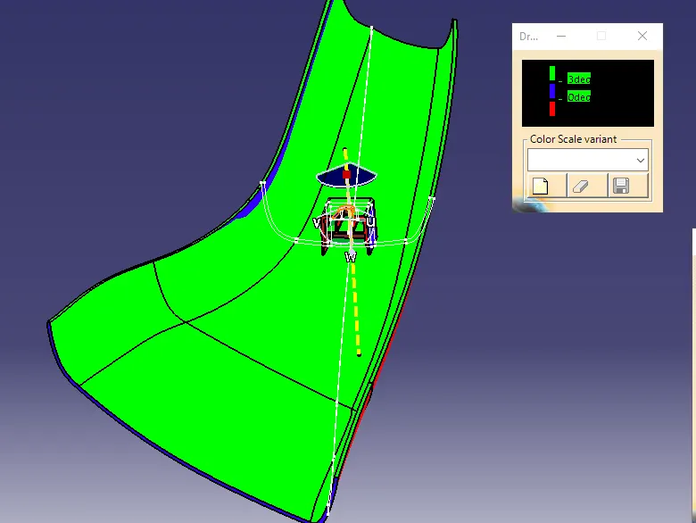
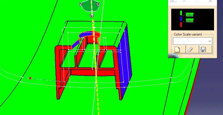
To create the tooling axis, I extracted a surface from class A and created a point in the middle of the surface by using the point command and created a line at that point through the x-axis. Now, I performed a draft analysis check from that line whether the created tooling axis is in the correct position or not. If in the draft, analysis check the surface highlighted with green colour on both sides of the surface the tooling axis is in the correct position and direction.
DRAFT ANALYSIS FOR CLASS A SURFACE:
We do perform the draft analysis check for class A surface before we make solid and creation of B-side features. Initially I align the compass to the tooling axis and I gave a 3deg draft angle for the green colour in the colour bar. If the surface is highlighted in green colour the draft angle is given properly for class A surface. If the class A surface is not highlighted fully in green colour, that might be the reason for the draft angle of the class A surface.
PROCEDURE:
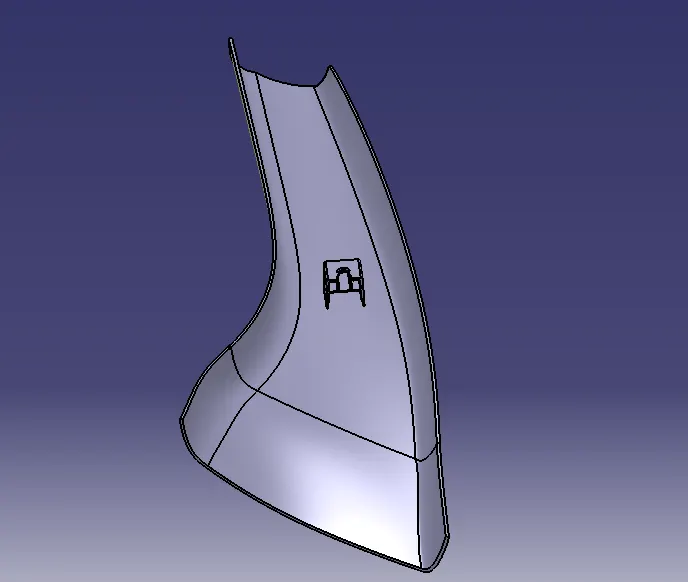
- From the Given Class A surface, B Surface has been created by offset command
- By doing this there were many missing elements in the CLASS B surface
- Sorted out each and every missing element in the Class B Surface with help of various commands like blend, multi-surface, offset, join(remove the surface), trim, offset, and more
- Once the surface is finished with the outer boundary
- After completing the b surface the Class C Surface is created from the Class A surface by sweep command
- As we cannot sweep the whole boundary the sweep is used to target continuity
- And with the join command join all the sweeps into one Class C surface
- Once the Class C surface is formed with no internal boundary
- Trim class C and Class B surface together
- Once the trim is created join the Class A Surface with trim
- Check whether there is any boundary in it to confirm the closed body
- Once confirmed using a close surface to create the part body
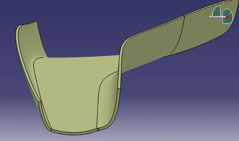
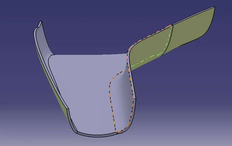
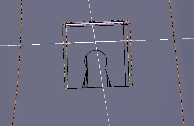
- For Doghouse Creation, create a sketch on the surface of the body
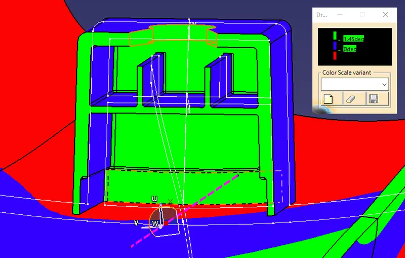
- Sweep the sketch with the draft of 1.5 deg and then create the wall of the dog house
- The top of the Doghouse surface is closed with the offset of the surface
- Now make the surface into the part using the thick command
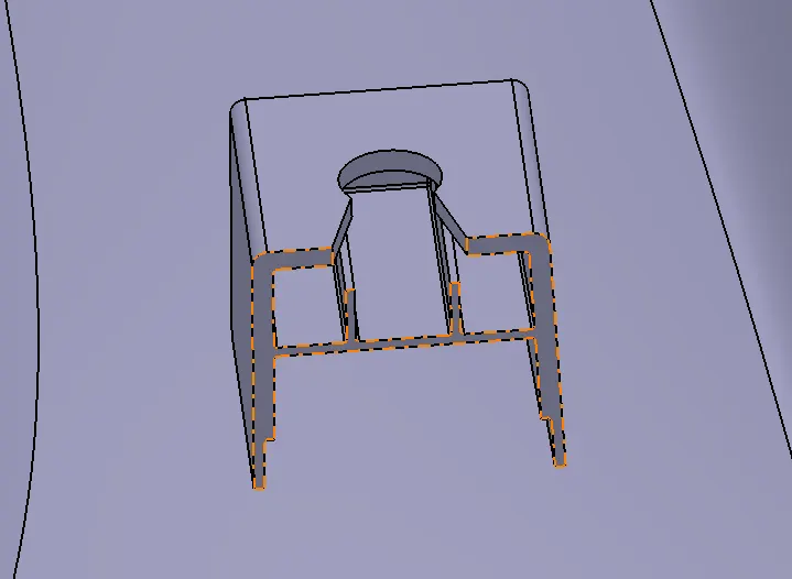
- Once the wall and top part are made the dog house rules should be followed create the part wall at the bottom of the dog house by height should be 3 to 6 mm and thickness of 0.4 times the thickness of the element
- Cut out as given in the diagram should be removed from the part
- Once it is created assemble the dog house with the door trim
- The reference of the same are taken from the master section given.
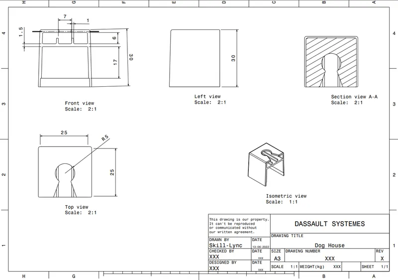
See attachment file PPT and Cat Part included