Week 11 - Project - A pillar Design with Master Section
Week 11 - Project - A pillar Design with Master Section
Inputs:
-
Class A Surface
-
Master Section 1 -Dog House Front-Section
-
Master Section 2- Dog House Middle Section
-
Master Section 3-Dog House Ribs Details-1
-
Master Section 4-Dog House Ribs Details-2
-
Dog House Drawing 1- Cylindrical Profile
-
Dog House Drawing 2- Cuboidal Profile
-
Pillar Component Thickness- 2.5mm
Tasks to be done:
-
Generation of Solid Model for Pillar Component using Data given in Master Sections and Class A Surface.
-
Generation of a Solid Model for the Dog House using Data given in Master Sections and drawings.
-
Locating the Dog House on the Pillar Component as shown in the Master Sections.
Assumptions & Considerations:
-
The direct Offset Method is used for the solid model generation of the Pillar Component and component thickness is taken to be 2.5 mm.
-
There are 2 drawings given for the Dog House- a) Cylindrical Profile, and b) Cuboidal Profile. As there was no specification as to which one has to be used for the challenge, the cuboidal profile has been chosen.
-
It was noticed that there were differences in the Dog House dimensions shown in the Master Sections and those given in the drawing. Hence the Dog House has been made using the master section dimensions. The drawings have been referred to, only for the dimensions not visible in the Master Sections.
-
There are 2 master sections cut across the Pillar Body, one along the breadth and another along the length. The one along the length is exactly perpendicular to the Dog House Front Plane. Maximum dimensions have been taken from this Section itself. Example: Main Tooling Axis and origin of the Pillar, Location (X-axis), Width, Height, draft angle, and internal ribs dimensions for the Dog House.
-
The master section cut across the length of the pillar is not cut exactly perpendicular to the Dog house Side plane. However, it has been used for limiting the length of extremities of the dog house as well as its internal ribs dimensions.
Design Steps Involved:
-
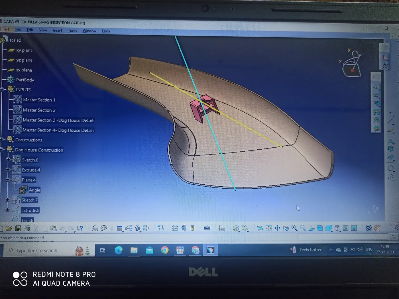
Determination of Main Tooling Axis for the Pillar & Dog House.
- The Tooling Axis of the main component and its B-side features are the same, as they are made out of the same tool. You may require a side core axis for achieving side cavities, but the main tooling
- a
- xis will remain the same. Hence the vertical Tooling Axis for the Dog House will also be the Tooling Axis for the main component. Master Section 2 was used to determine the same.
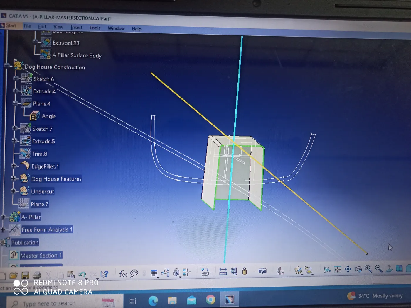
- The bisection method was used for the calculation of the Tooling Axis. For this, a plane was inserted along the plane of Master Section 2. The left and rightmost edges of the Dog House were extracted from the master section 2 on the inserted plane. The line bisecting these two lines was taken as the Tooling Axis.
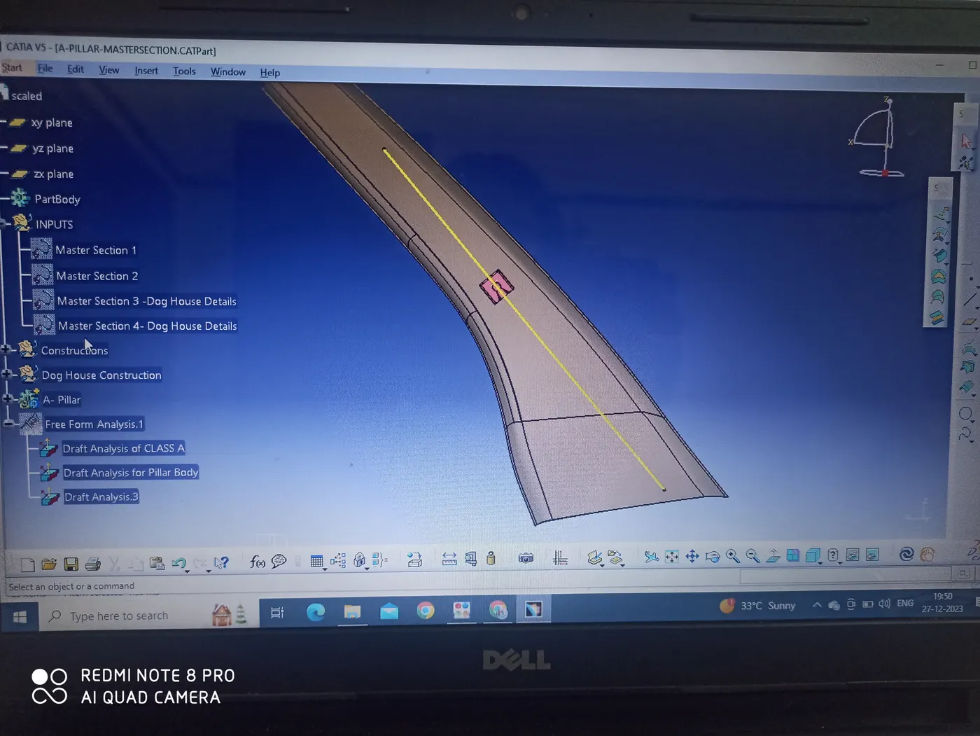
- A draft analysis of Class A Surface was done with this line as the Tooling Axis and the surface perfectly satisfied the draft angle requirements. Hence this line was taken as the Main Tooling Axis of the Pillar component and the Dog House. The side core axis for Dog House was determined at a later stage.
- For more details refer to the geometrical set for Tooling Axis in the CAD.
-
Creation of a Solid Model for the Pillar.
The solid model for the Pillar Component was created as follows:
-
Creation of B Surface
-
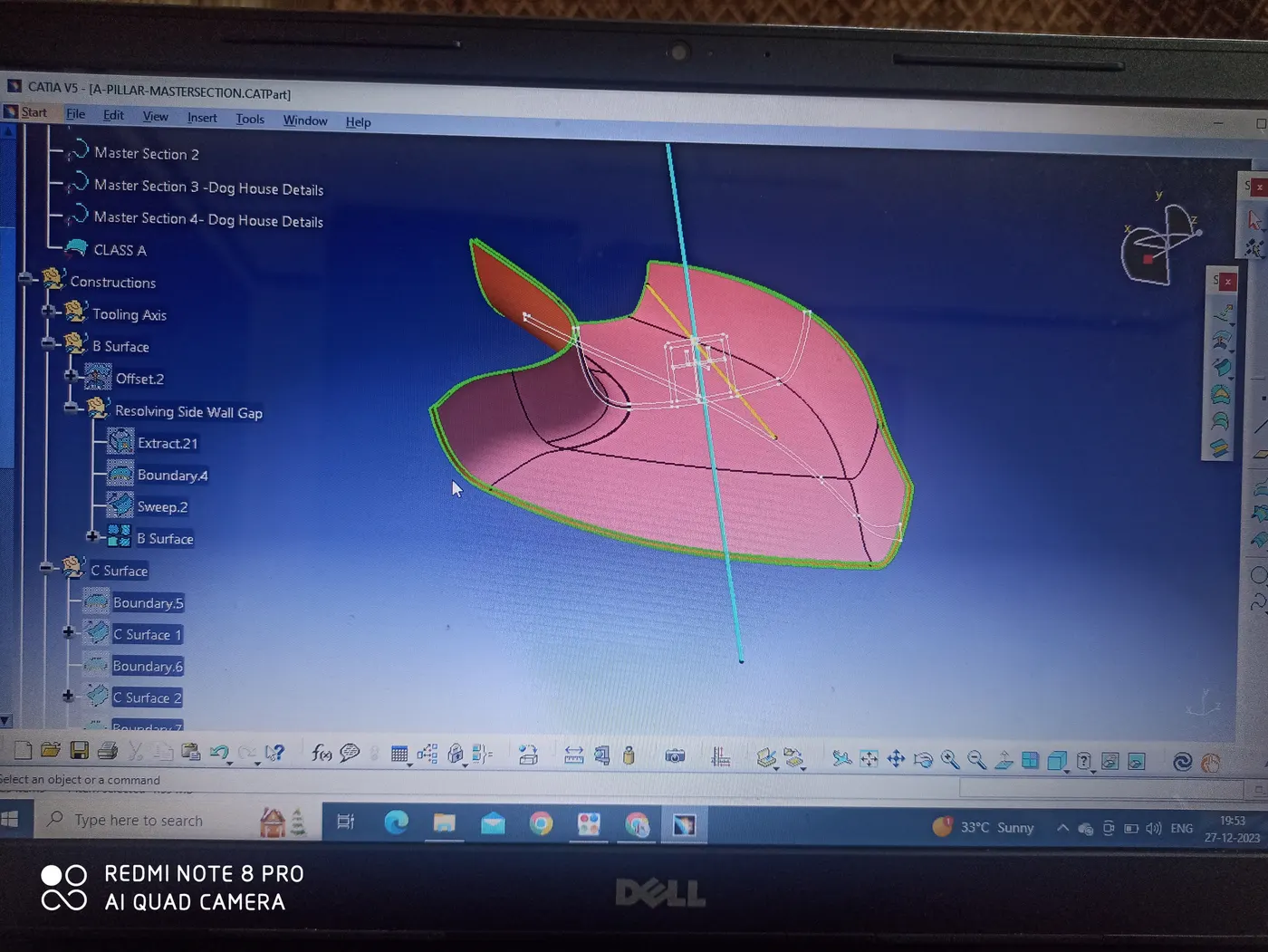
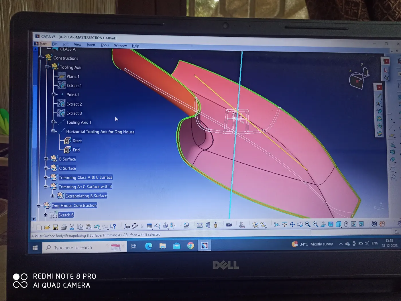
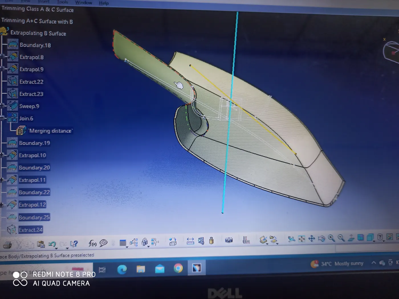
The direct offset method was used for the creation of the B surface for the Pillar Component. The Class A surface was offset upwards in the direction of the Tooling Axis by 2.5 mm ( as the component thickness was given to be 2.5mm).
-
Upon offsetting it was noted that almost the entire Class A Surface got offsetted correctly except for one missing patch. This missing patch was mended using the ‘Sweep Command with Reference Surface’. The vertical and horizontal edges of the missing patch were extracted and used as the profile & guide curve respectively. The surface column was left blank. The missing patch was thus obtained and joined to the earlier offsetted surface. This resulted in the final B Surface of the Pillar Component.
-
For more details refer to the geometrical set for B Surface in the CAD.
-
Creation of C Surface
-
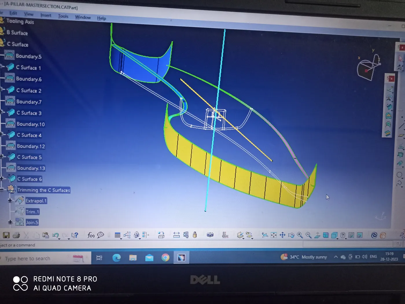
The C Surface for the Pillar component was obtained in 6 patches.
C Surface 1- At a draft angle of 3 degrees with the Main Tooling Axis
C Surface 2- Perpendicular to the Class A Surface
C Surface 3- At a draft angle of 3 degrees with the Main Tooling Axis
C Surface 4- Perpendicular to the Class A Surface
C Surface 5- Perpendicular to the Class A Surface
C Surface 6- Perpendicular to the Class A Surface
These Surfaces were trimmed and joined together to get the Final C Surface of the
Pillar component. For more details refer to the geometrical set for C Surface in the
CAD.
-
Creation of Surface Body and solid Body for Pillar component.
-
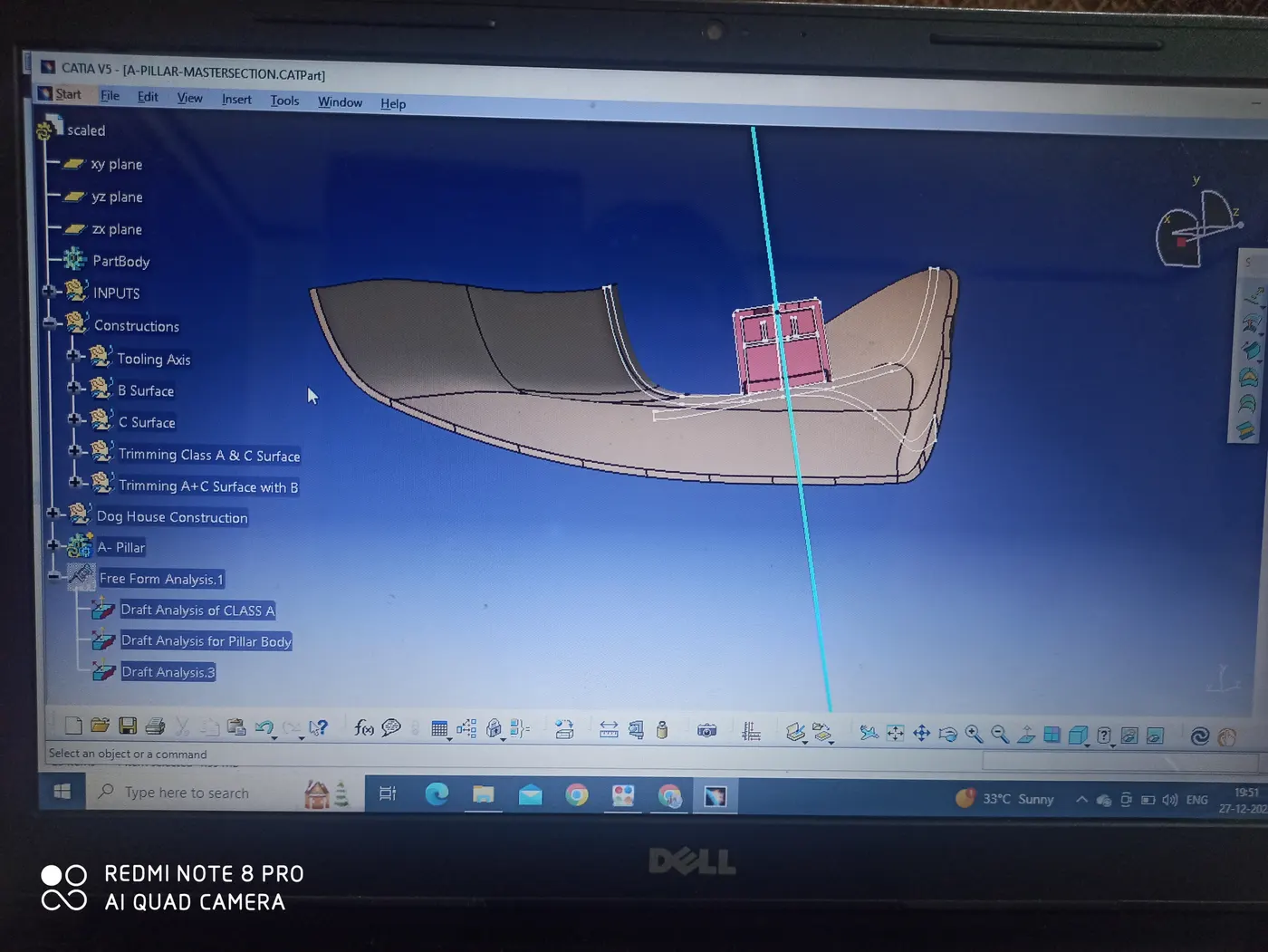
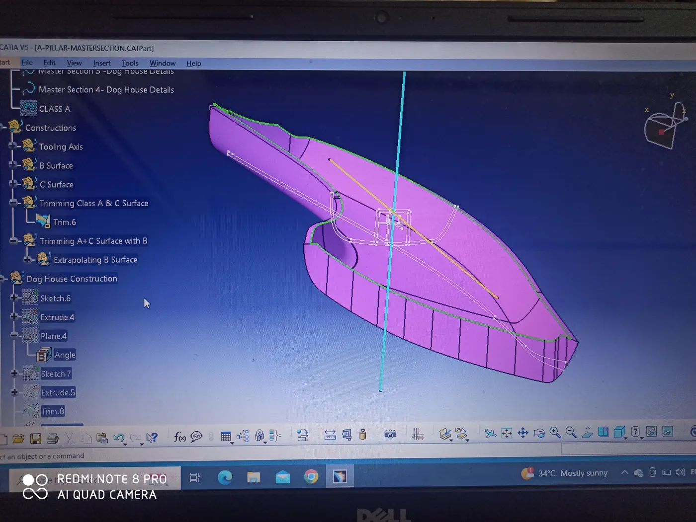
The C surface was trimmed with Class A surface. The A+C Surface was then trimmed with the B surface to get the close surface body for the Pillar component. This close surface body was then converted into the Solid body through close surface command in the part workbench.
-
A draft analysis was this solid body and it was noted that all the surfaces satisfy the minimum draft requirements successfully.
For more details refer to the geometrical set for A, C & B surface trim and Draft
analysis for Pillar Solid Body in the CAD.
-
Creation of a solid Model for the Dog House.
The draft house model was made using the details given in the Master Sections 1,2,3 & 4 and the details drawings for the Dog House. Out of the given 2 options for Dog House Profiles (Cylindrical and cuboidal), the cuboidal profile has been chosen and the model is made accordingly.
-
The placement of the Dog House in the Pillar component is done with the help of limitations shown in the master sections.
-
Mastesection 2 has been used to make the front view of the dog house and master section 1 was used to limit its length extremities. Using both master sections, the skeleton surface of Dog House was drafted.
-
This surface was thickened towards the inside direction by 2,5mm ( dimension taken from dog house master section).
-
The height of the dog house was taken extra deliberately, to trim it easily with the Pillar component.
-
For making the undercut in the dog house, its three walls were offsetted. Also, the pillar surface was offsetted by 4 mm to give the undercut height. All the surfaces were trimmed together to obtain the undercut surface skeleton. The dog house model was then split using the undercut skeleton.
-
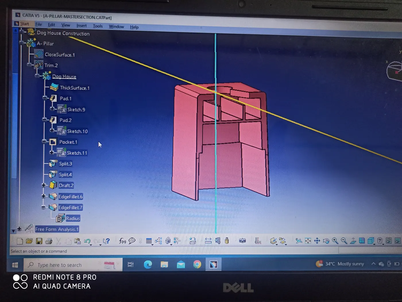
The dog house was then given the ribs on the inside surfaces. The master sections 3 & 4 were used for the required dimensions.
-
Please note the outside faces of the Dog House already have a draft of 1.5 degrees with the man Tooling Axis. As they were made using the master section profile. But for the inner faces, we have to make a separate side core axis. For this, a line is drawn at the origin point of the dog house. This was taken to be exactly perpendicular to the front face of the Dog House and termed the side core axis. This side core axis is used to draft the inside faces and the ribs made over them.
-
Each inside face ( Dog House walls & the ribs faces) is given a draft angle of 0.5 degrees with the side core Axis. Another drfat analysis of the dig house is done for inside faces taking the side core axis as the tooling direction. It was noted that they satisfy the required draft angle.
-
In the end, all sharp edges were given a minimum fillet of 0.1mm radius. That is how the solid model for Dog House was made. For more details, refer to the respective geometrical sets for Dog House & draft analysis, in the CAD.
-
Trimming the Dog House with the Pillar at the correct location
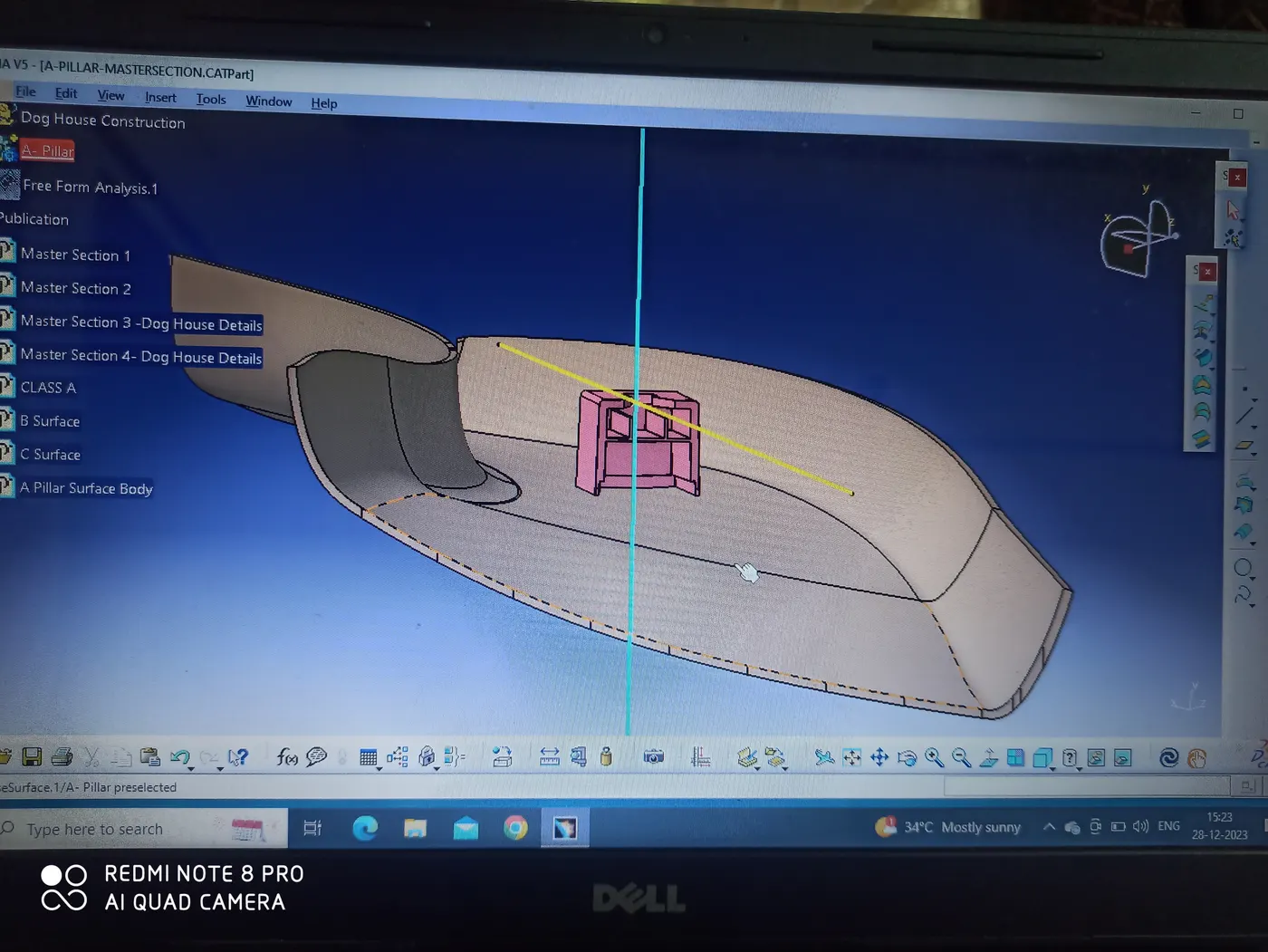
The Dog House model was then union-trimmed with the Pillar component and the challenge was complete.
Please note that the important parts of the model like the sections, Tooling Axis, side core Axis, Class A, B & C surfaces have been published and the images from the CAD have also been added for better understanding.