Week 11 - Project - A pillar Design with Master Section
OBJECTIVE
To explain the creation of Complete body using master section and also create dog house using the master section.
INTRODUCTION
Tooling axis is an axis which is the axis along which the whole part come out from the mould which is molding in core and cavity arrangement.
Tooling direction: It is the main focus for part because it defines the movement of the mould part and the chance of plastic part coming out from the core and cavity setup.
In other words, the mould is built from two separate halves (core and cavity) and tooling direction is basically defines the direction of mould pulls out. Tooling direction is also known as primary direction.
Creation of Tooling Axis
- First of all, import the Class A surface in surface work bench and check for any irregularity or discontinuity by boundary icon.
- If there are any irregularity, correct it and after that analyse the Class A surface for Tooling Direction.
- After that extract front and back side of the dog house from master section and create a point using these two extracts.
- After that extract both side of the dog house from master section and create a dummy tooling axis using the centre point and bisector line option.
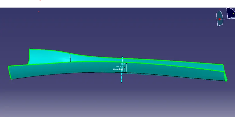
- For Main Tooling axis we use the centre point and front side extract and create it as shown below,
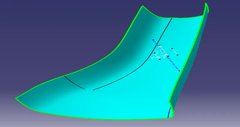
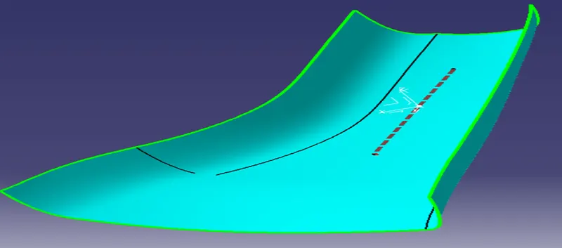
- For side tooling axis first we create a plane at centre point of the dog house master section and using the first point and direction perpendicular to plane and create the side core tooling axis.
Draft analysis:
Draft analysis command is generally enables us to detect that the part can easily remove at certain angle. This analysis of the draft angle is shows colours for different ranges of angle where the deviation from draft direction at any point corresponds to specified values.
For drafting analysis,
- First, we click on insert, after that go for analysis and then feature draft analysis icon.
- After that click on compass and pick the axis tree and put it on the Tooling Axis and lock it.
- Then click on colour scale and feed the angle range for the particular colour.
Below the picture showing the Draft analysis of the Class A surface, CLOSED BODY and DOG HOUSE.
1.Draft analysis for Class A surface the part
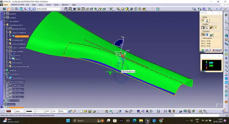
There is and defect in the class a surface which is at an angle of 2.81deg which is not acceptable.
2.Draft analysis for Closed body
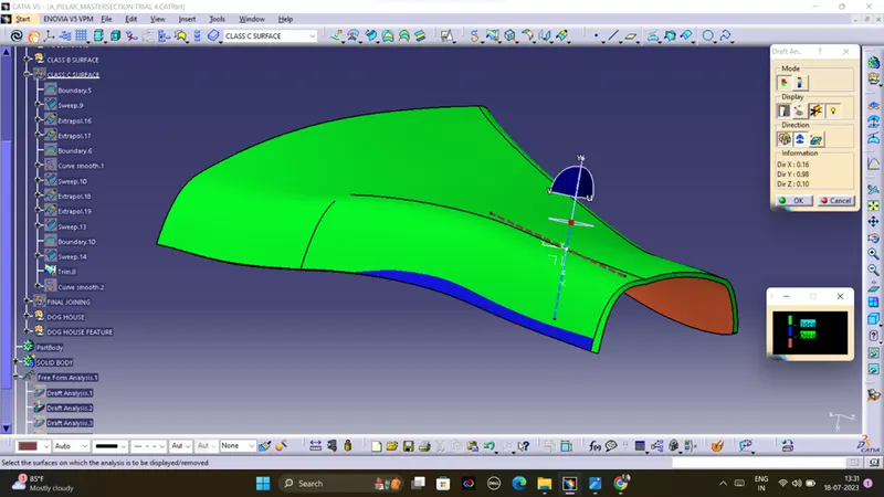
There is all clear except that class a defect. All class B and Class C surfaces are ok.
3.Draft analysis for Dog House using Main Tooling Axis
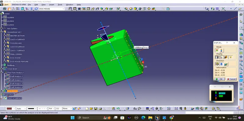
The outer surfaces of the dog house are showing an angle of 1.488deg which is acceptable according to design rule.
4.Draft analysis for Dog House using Side core Tooling Axis
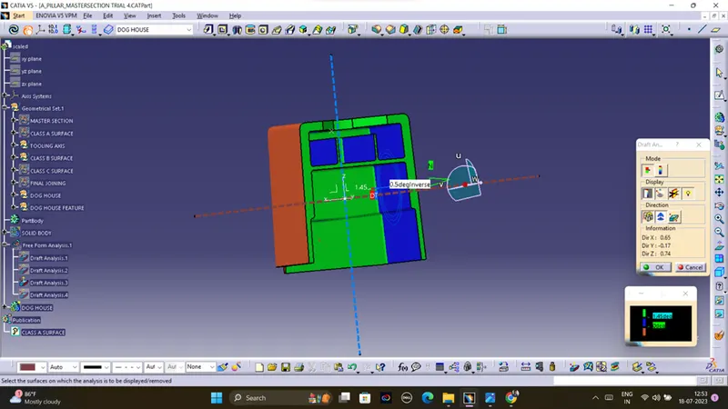
The analysis shows an angle of 0.5deg which is acceptable according to the design rules.