Week 11 - Project - A pillar Design with Master Section
A PILLAR DESIGN WITH MASTER SECTION
AIM
To develop the A Pillar Design, I used the master section as the intersecting sketch with the Class A surface. I then created the tooling axis and conducted a draft analysis for the final solid part.
CLASS A SURFACE
The visible surface is classified as a Class-A surface, which is primarily responsible for defining the component's aesthetics and appearance, as it reflects the design preferences of the styling team. This surface serves as a basis for the part design engineer to incorporate all the necessary engineering specifications into the component.
To assess the continuity of the provided surface, you can use commands like Join or Boundary. These commands will help ensure that the surface is smoothly connected and free from any imperfections or disruptions, which is crucial for both the visual quality and functional aspects of the component.
TOOLING AXIS BISECTING LINE METHOD
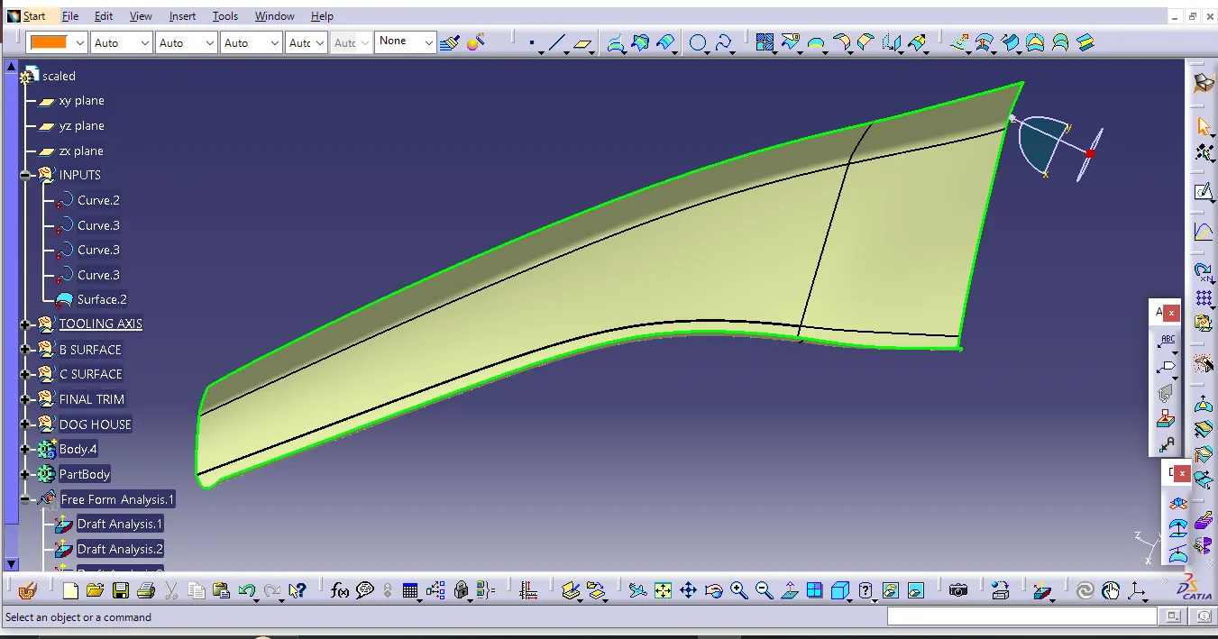
The technique of using a dummy tooling axis involves the application of the bisecting line method to ascertain the correct tooling axis. In this method, a line is employed to bisect two lines, or it highlights an error if the two lines are parallel. By intersecting the surface with the relevant plane, we can assess whether the surface is suitable for tooling. This process results in the creation of a drawing featuring two lines, which can then be bisected to generate a third line at their intersection point.
SIDE CORE AXIS
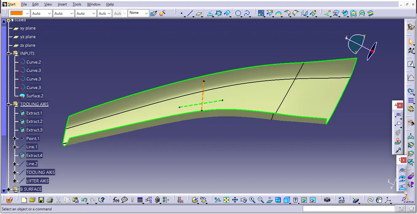
To establish the side clearance axis for the dog house, there can use the bisecting line method or create it utilizing the provided master section.
DRAFT ANALYSIS OF CLASS A
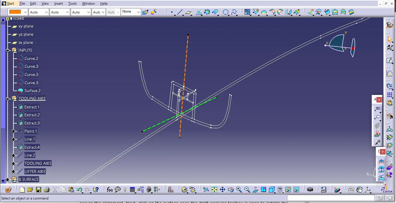
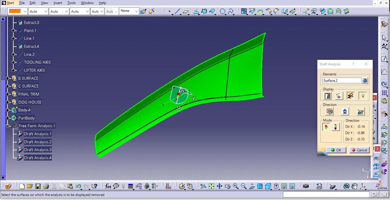
Here can utilize the Feature Draft Analysis tool available in the Analysis toolbar to conduct a draft analysis. Locate the compass and ensure it is aligned with the tooling axis. After aligning, click on the lock symbol to secure the alignment. Next, click on the surface once the draft analysis toolbox is open to initiate the analysis process.
CREATING CLASS B AND C SURFACE
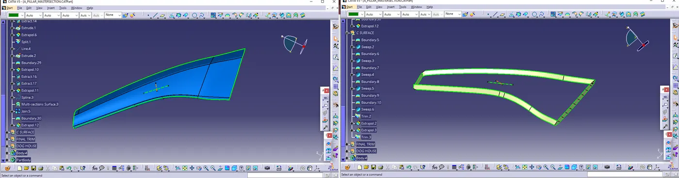
Begin by offsetting the surface by 2.5mm, being mindful that some errors may occur, resulting in the removal of certain parts. Ensure to select the option 'keep all sub-elements' when prompted. Utilize commands such as fill, sweep, boundary, extrapolate, and trim to effectively close any resulting patches. Finally, merge all the elements together to complete the process.To begin, extract the boundaries of the Class A and B surfaces. Following this, utilize the sweep option to create the C surface.
FINAL OUTPUT
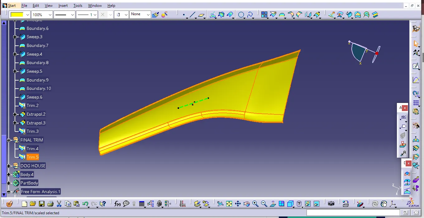
Proceed to trim the Class A, Class B, and Class C surfaces to achieve the desired output. Following this, utilize the close surface feature in the part workbench to convert the surfaces into a solid body.
DOG HOUSE
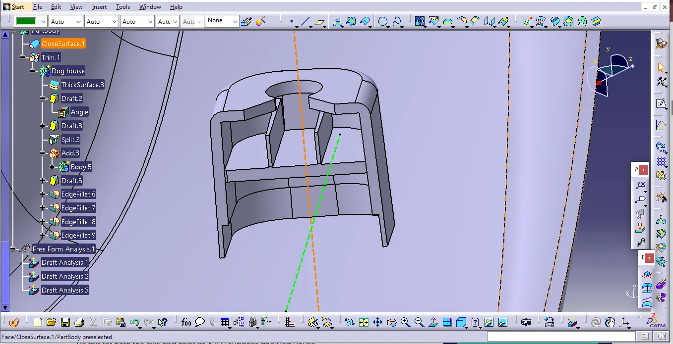
A plastic design component known as a "dog house" is utilized, primarily serving as a supporting element. To enhance its strength, snaps, locators, and screw bosses might be incorporated. Draft analysis is conducted on the dog house to reduce the risk of component breakage during ejection from the mold cavity. Additionally, various engineering features are integrated into the B-surface of the dog house.
DOG HOUSE CREATON
Dog houses serve the purpose of preventing sink marks caused by screw bosses on Class-A surfaces and addressing the length issues associated with attaching screw bosses to other components. They are particularly advantageous when the part requires screw bosses perpendicular to the tooling direction.
Guidelines for dog house dimensions are as follows:
- The C thickness should be 40% of the main wall thickness T.
- The minimum width of the dog house should be 12 mm.
- The height of B should fall within the range of 3-6 mm.
FINAL DRAFT ANALYSIS
Here can use the Feature Draft Analysis tool in the software's tools to analyze the draft. Start by locating the compass and aligning it with the tooling axis. After aligning, click on the lock symbol to secure the alignment. Next, click on the surface once the draft analysis toolbox is open to initiate the analysis process.
Perform this process for both the axis and analyze the A, B, C surfaces, and the Dog House. This will ensure a comprehensive understanding of the draft angles and surface analysis across all components.
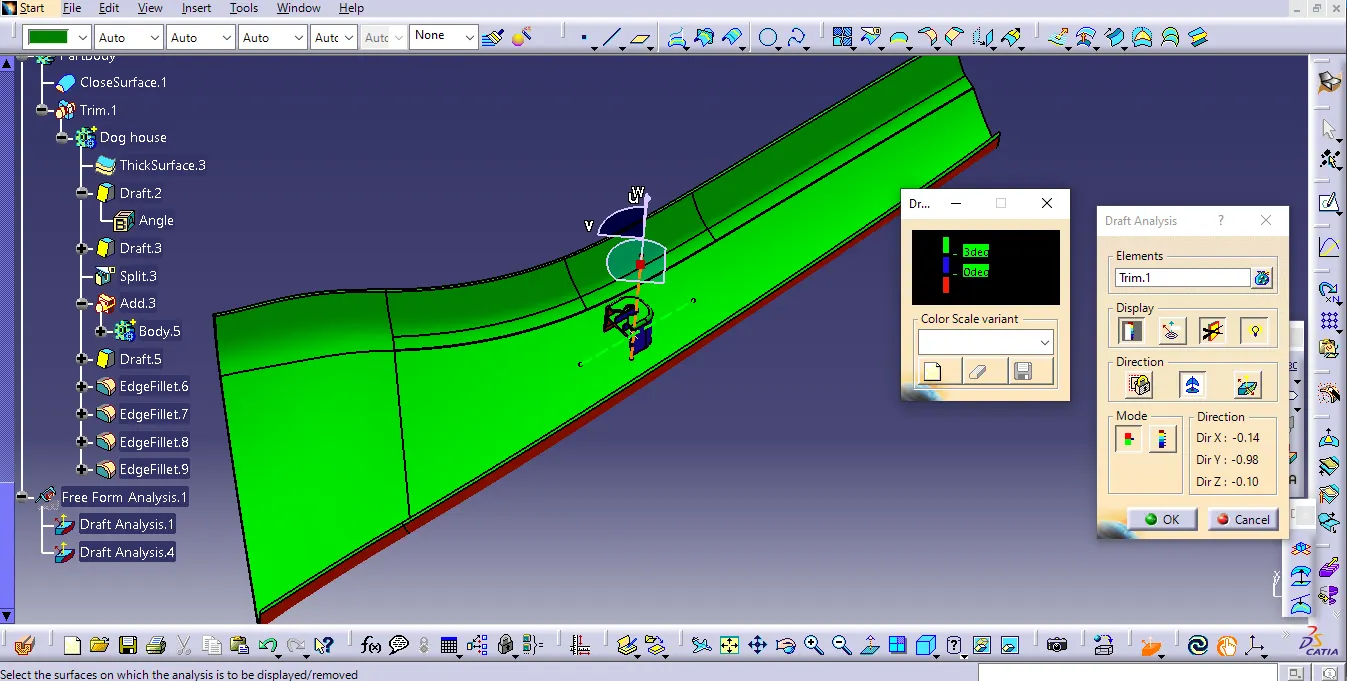
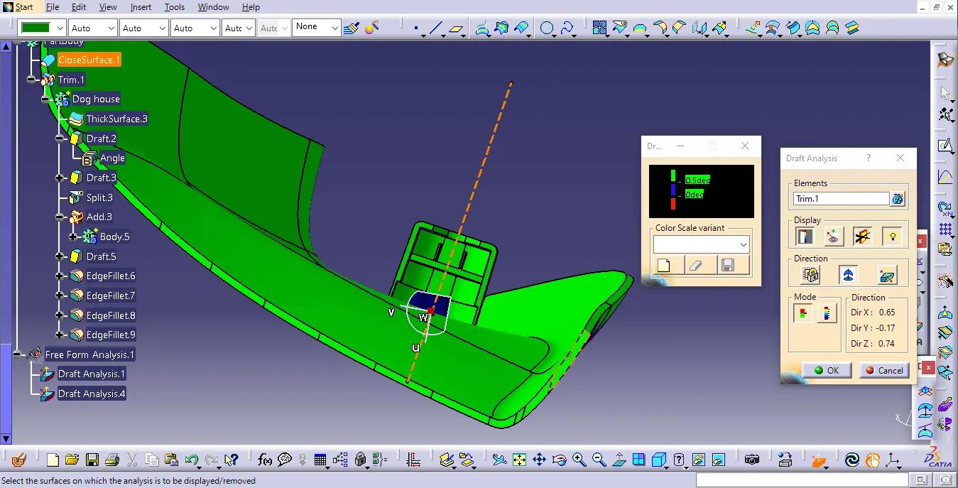
- Screenshots of the solid model with the proper color code of the draft angle in various orientations (Isometric, Front, Side, and Top View)
- Isometric view
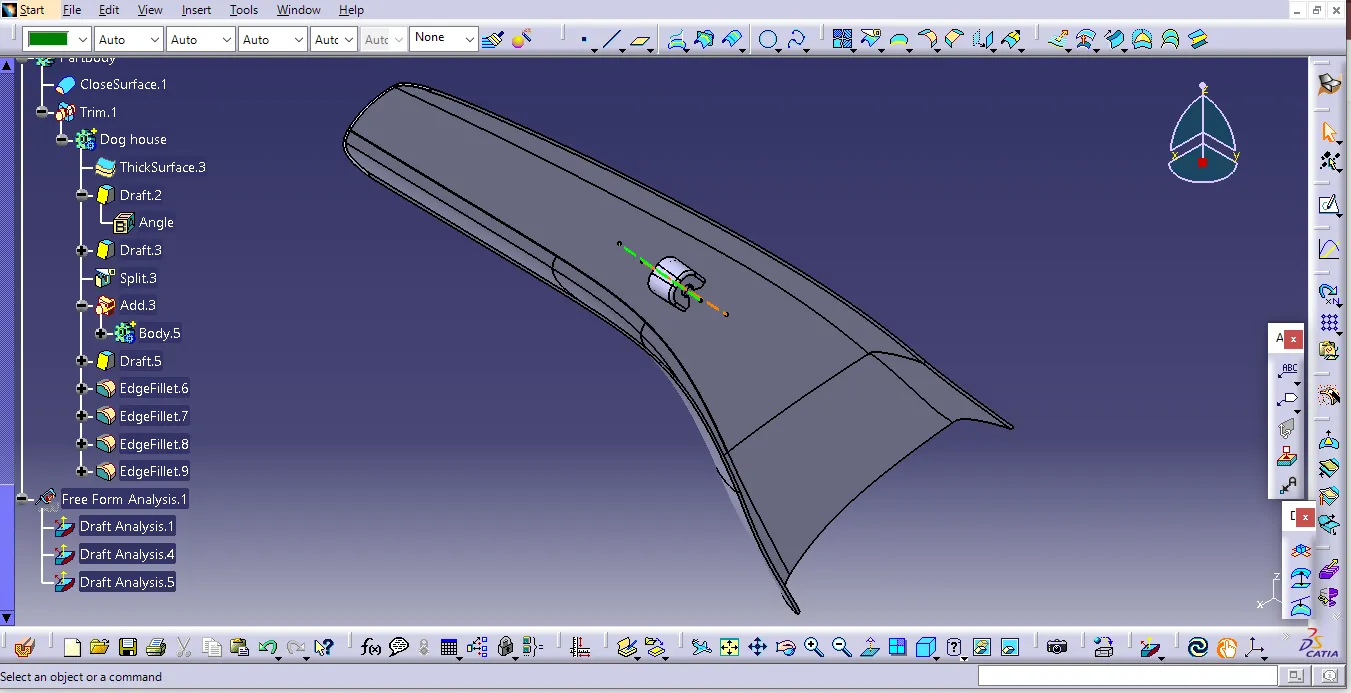
- Front view
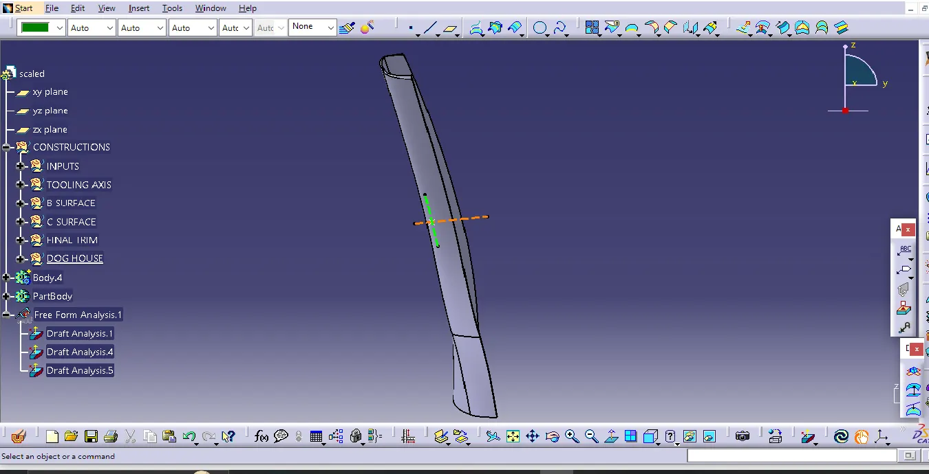
- Side view
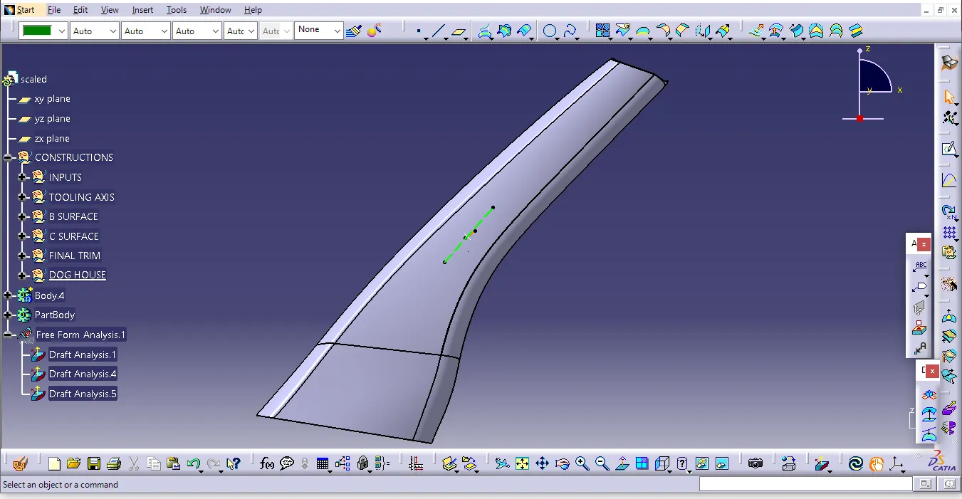
- Top View
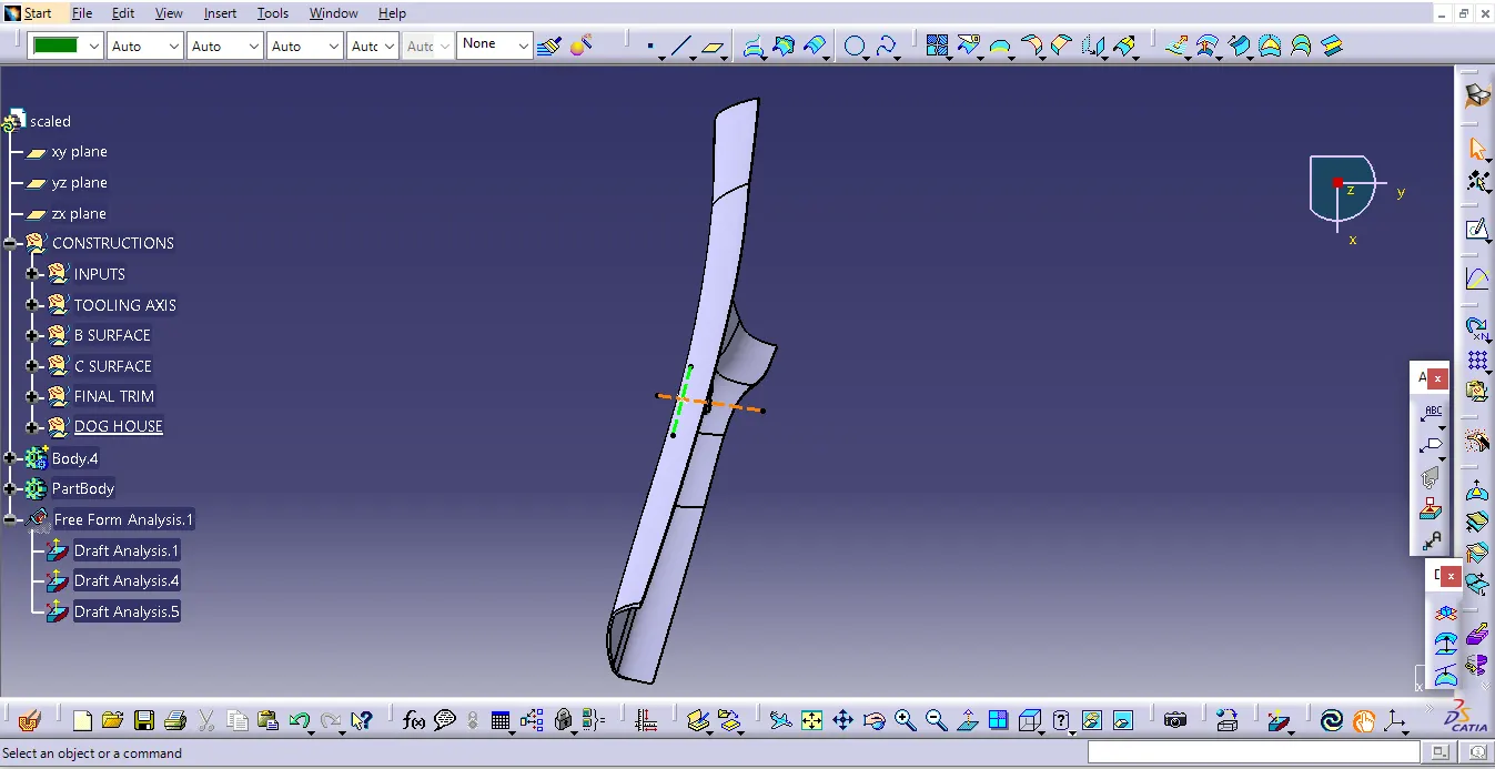
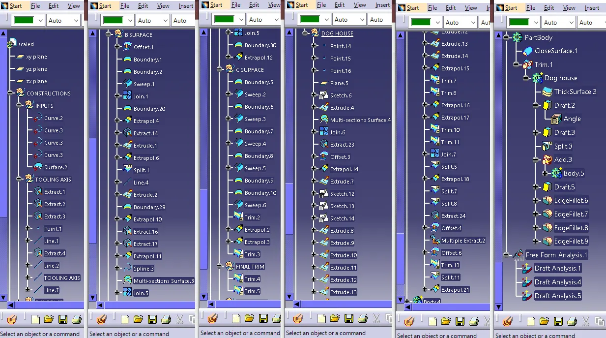
- Expanded Specification Tree (after completion of all steps):