Week 11 - Project - A pillar Design with Master Section
AIM:
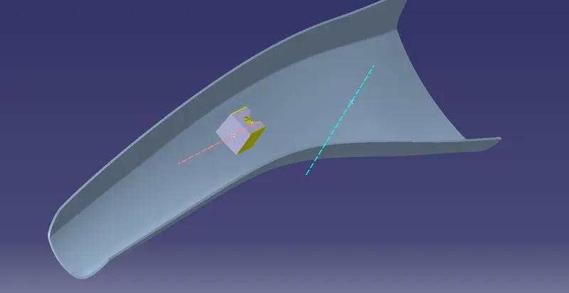
To create the A Pillar Design with the master section given as the intersection sketch with the Class A surface and create the tooling axis and perform the Draft analysis for the final solid part.
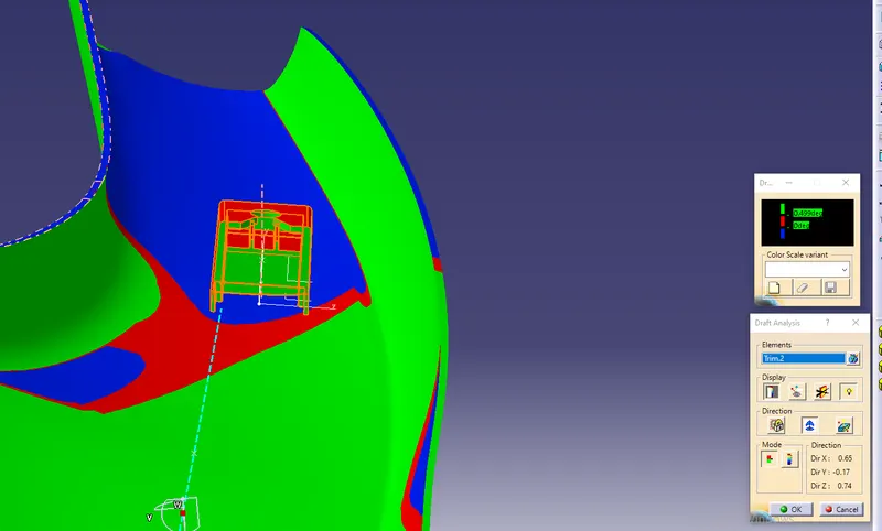
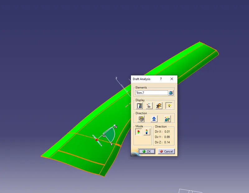
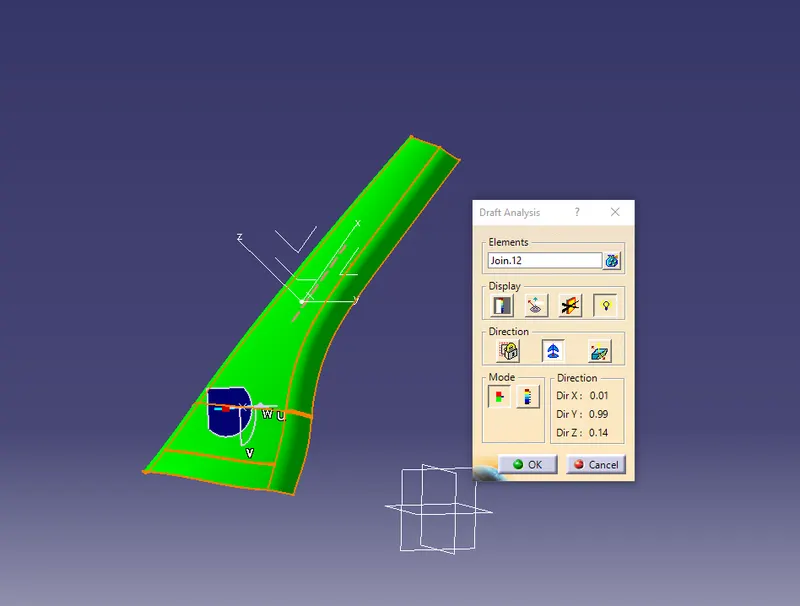
Report of draft analysis
In a draft analysis we have to position the tool direction on surface class A and the compass should be lock in the tool direction and then check the analysis under running point should check the draft angel on the surface oh the class c
If the
red represent - no draft
Green represent - positive draft on cavity side
Blue represent - negative draft on core side
Please check the report in given below attached file for draft analysis
dog house draft analysis
final trim closed surface draft analysis
class a surface draft analysis
Tooling direction
Main tool dirtection
We make a point & line in on the surface on for tooling direction
And the tooling direction depends upon the surface of draft angel given by as and then we move on the tooling direction
And the direction of compass should be an lock through the line along the surface
If the tooling direction to desired the cavity and core side of the surface
lifter tool direction
We make a point & line in on the surface on for lifter tooling direction
And the tooling direction depends upon the surface of draft angel given by as and then we move on the of lifter tooling direction
And the direction of compass should be an lock through the line along the surface
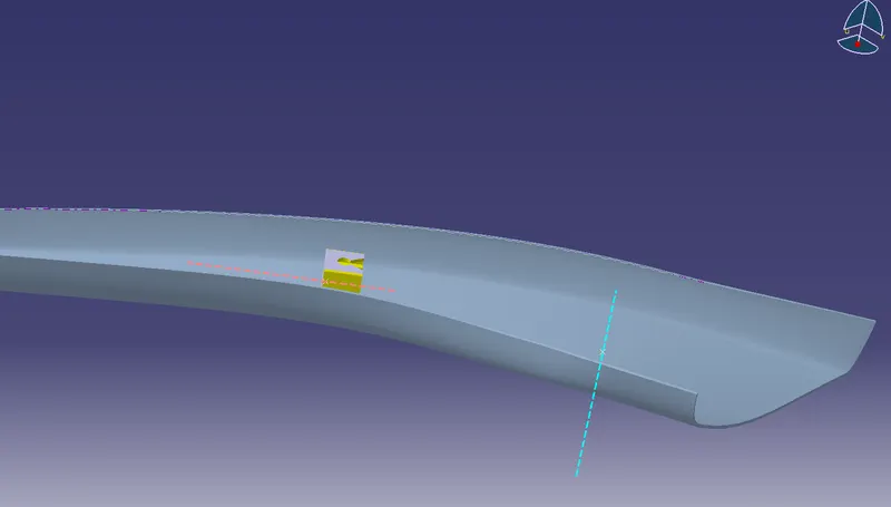
Surface A
Repair the class a surface there is a n number of surface we should be the join the all surface together in single smooth surface
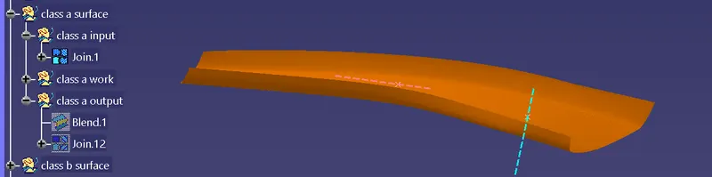
Surface b
- Create offset surface of Cin LASS-A about 2.5mm inward direction.
- Check for discontinuity and rework on the offset surface using extract, multi-extract, multi sections surfaces.
- Join the surfaces and ensure the final CLASS-B surface created has no gaps.
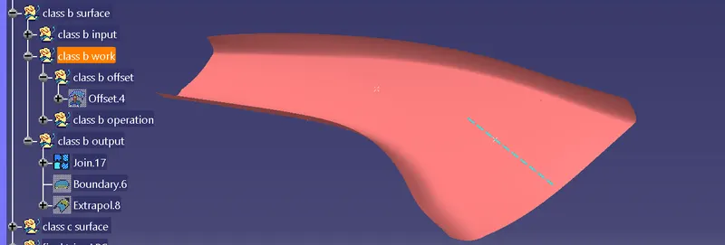
SURFACE C
The surface that joins class-A and class-B surfaarethe s is class-C surface. Class C is often specified for interior surfaces not readily visible, surfaces that will be covered by another part when assembled
- Create the sweep concerningerence to the surface and tooling axismulti-extractingting the CLASS-A boundary
- Join the sweep surfaces by using commands like extrapolate, trmulti-sectiontion surface.
- Finally join all the sweep surfaces and ensure the continuity of the CLASS-C surface.
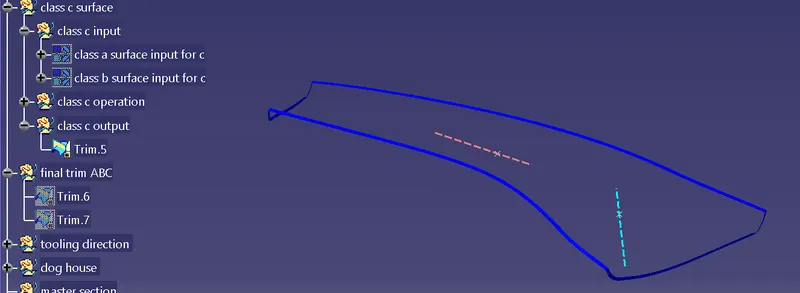
Sketch solving status’s geometry tab
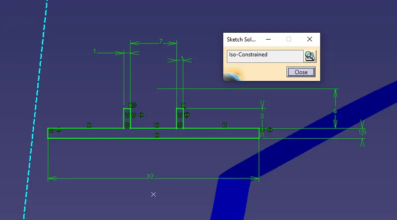
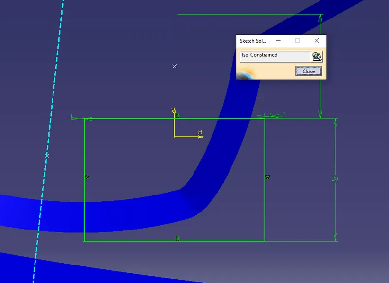
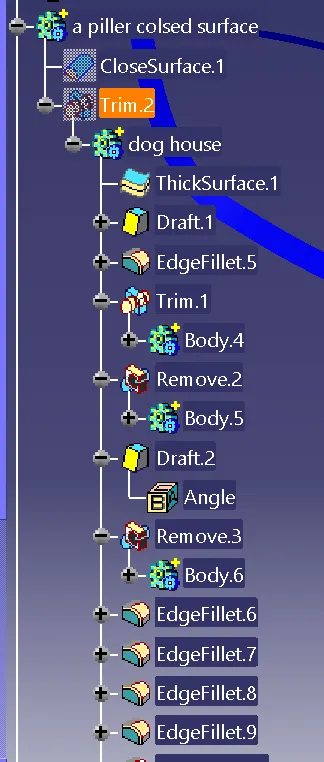
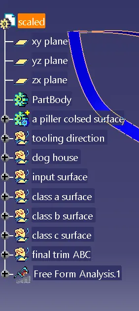
Detailed tree structure
solid part modeling & surface modeling
Picture of the 3D CAD
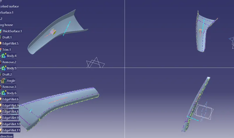
Create closed body