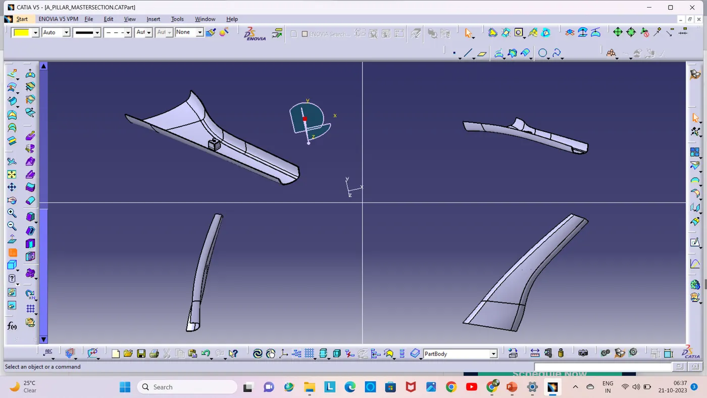
Week 11 - Project - A pillar Design with Master Section
AIM:
To create the A pillar design given as a intersection sketch with A class surface and create a tooling axis, then create a solid part, then create a dog house, and finally check the draft analysis of the final component.
Procedure:
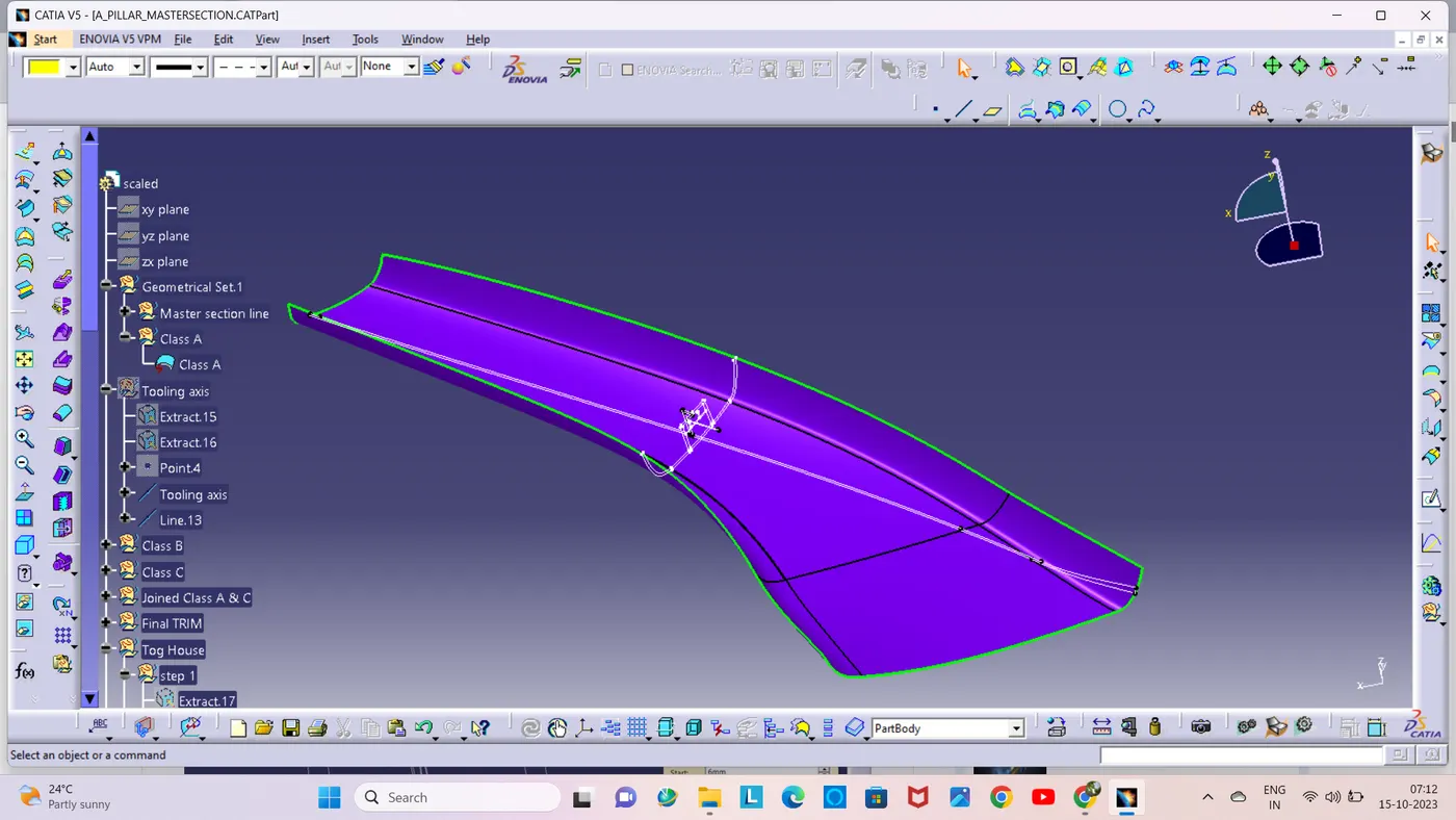
- Create the tooling axis and then check the draft analysis.
- Create class B & C surface through cross section sketch and class A surface.
- Create the solid component and check it is draft analysis.
- Create dog house considering the design rule.
Tooling axis:
The tool axis is the core of the axis or the direction of the cavity opening. This axis is important for determining component orientation in mold, core, and cavity design and for enabling component draft analysis.
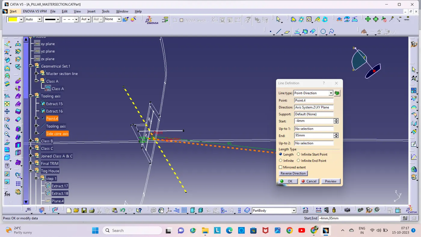
First I extracted two lines in the master section and then created a point between the two lines with the point command.
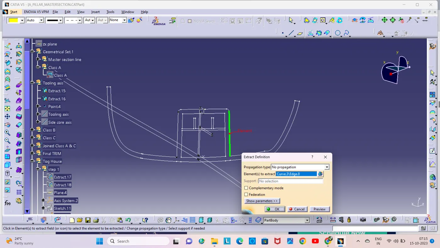
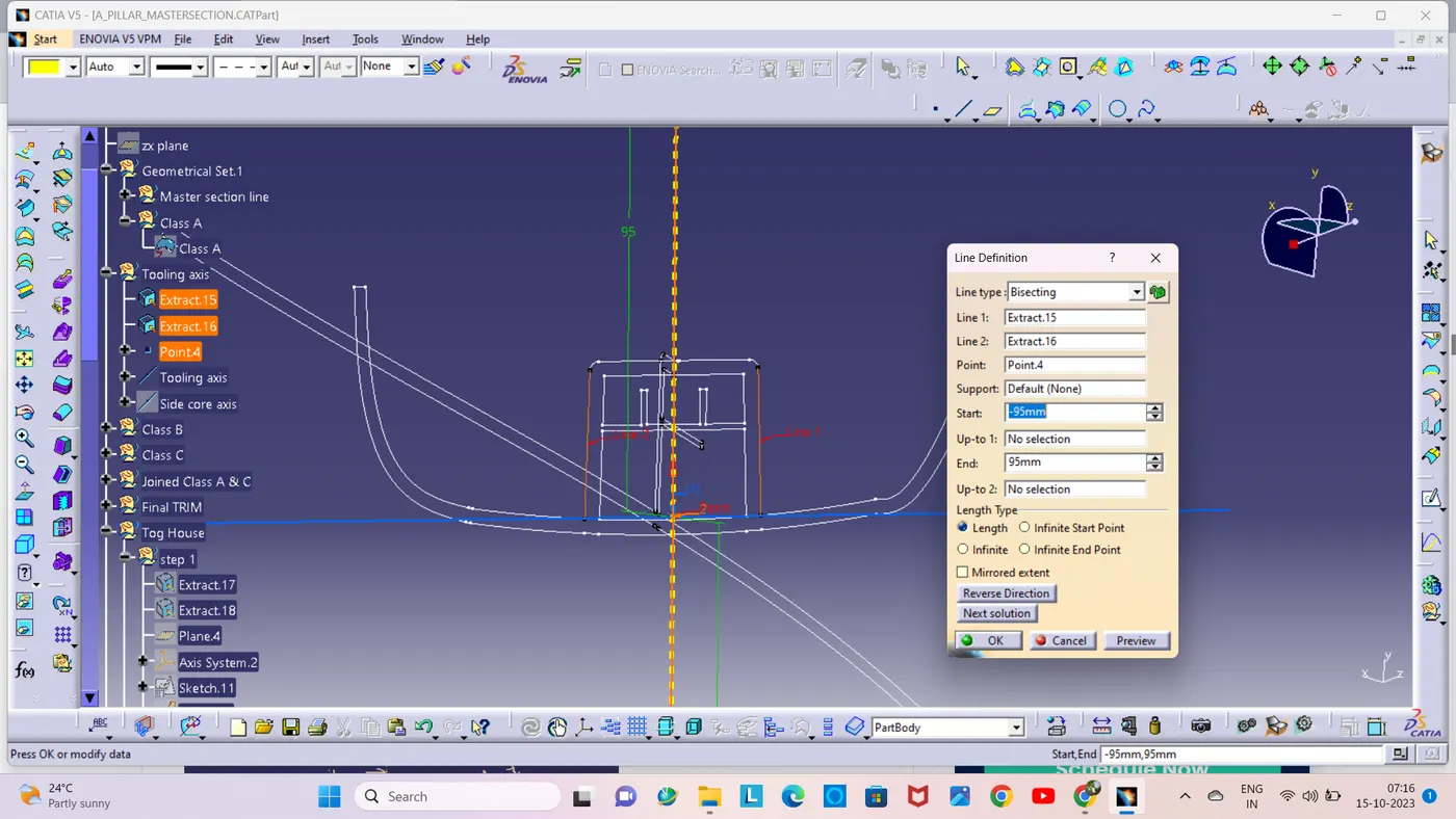
I created the tooling axis using the bisecting on line command using two lines.
Then created the side core tooling axis using the point and direction with line command.
Draft Analysis:
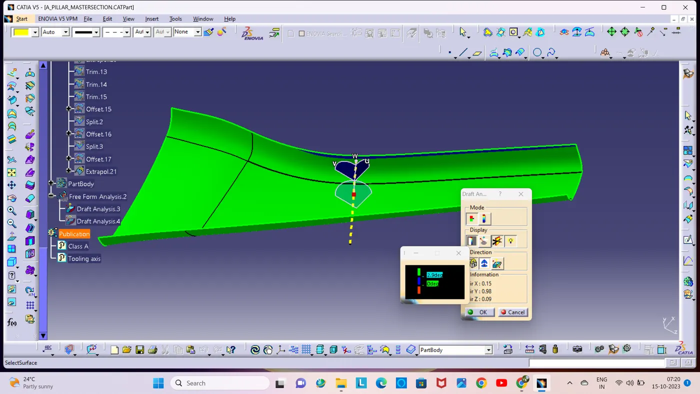
A draft analysis check is performed on a Class A surface before creating a solid part from that Class A surface to check whether a given Class A surface is correctly or not.
Class B surface:
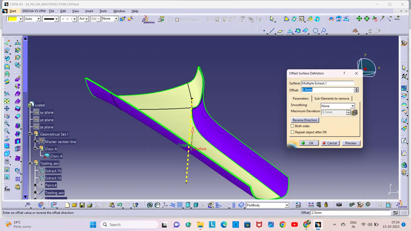
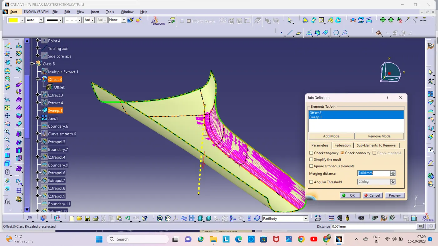
To initially create a class B surface, I measured the thickness of the primary section (2.5 mm). I offset the class A surface by 2.5mm inward direction.
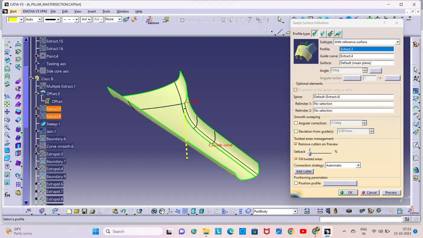
The styling fillets on the class A surface are not offset properly, some faces were missing, so I used the Sweep command to close the patch on the offset surface.
Then i joined the both surfaces using the join command.
Class C surface:
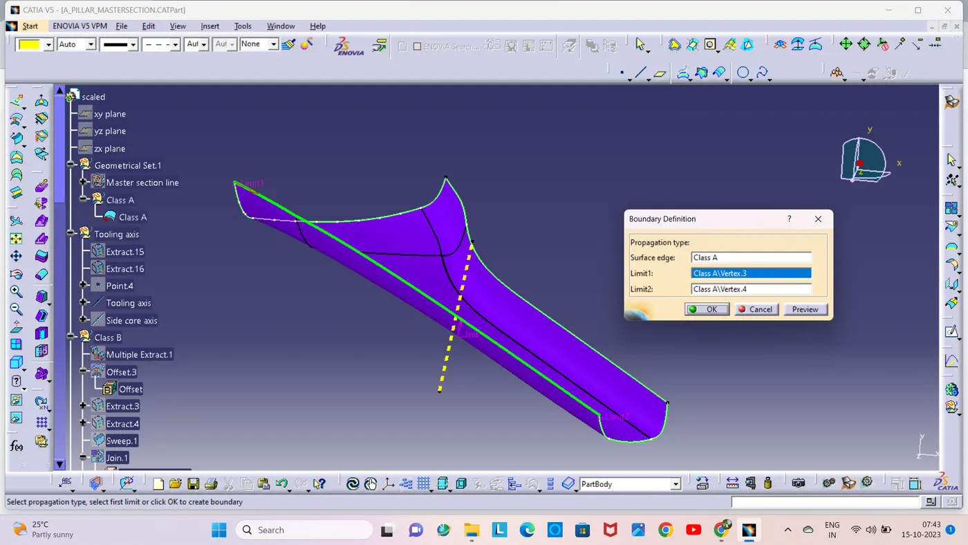
Create a Class-A outer boundary with the Boundary command, then use the Sweep command to create a Class-C surface.
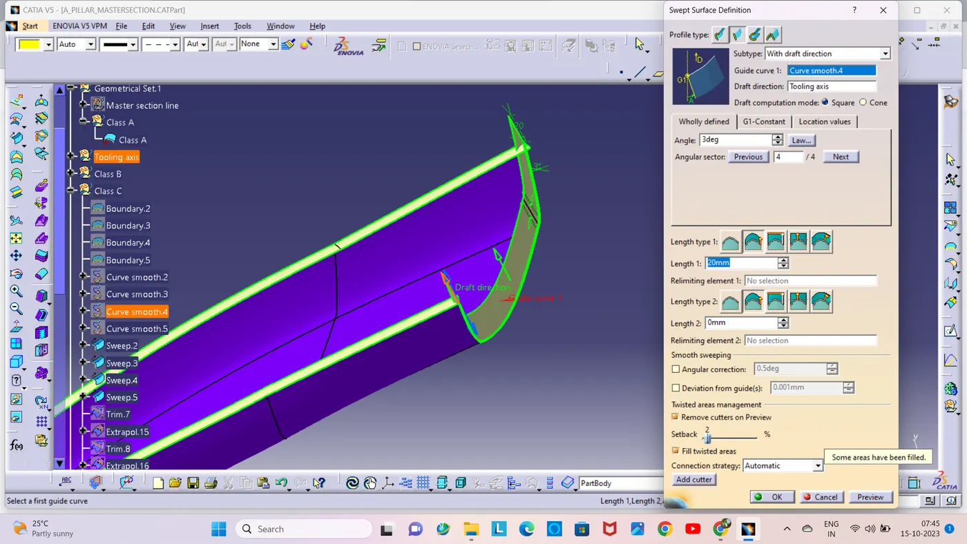
The Class-C surface is created by giving a minimum draft angle of 3mm in the sweep command.
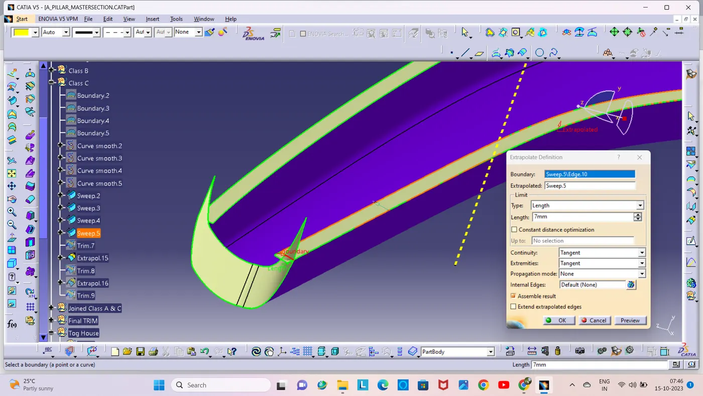
After the creation of the class C surface, the surface edges are needed to be extrapolated to intersect properly from all 4 sides.
I trim the extrapolated surface to get the joined class C surface.
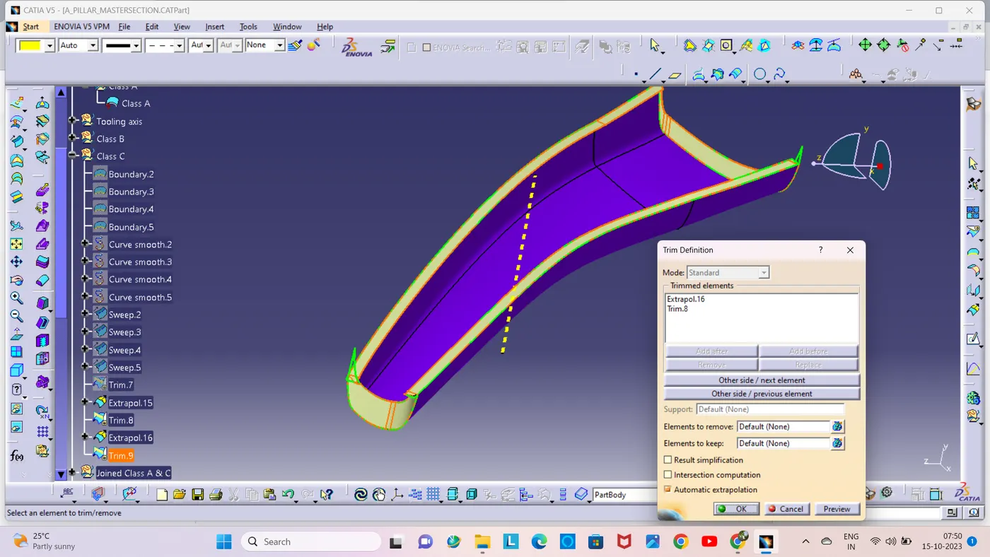
I joined the class A surface and the class C surface to get a single surface of class A+C surfaces.
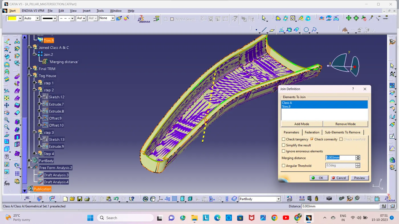
Closed surface:
Check that the Class-B surface intersects the Class-C surface correctly.
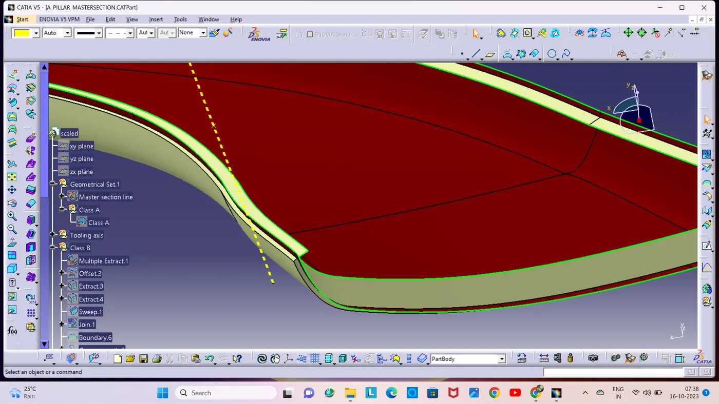
A closed surface is created using the Trim command in Class-C and Class-B surface.
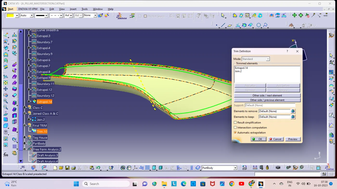
To check the trim surface created using the boundary command, if it does not get the boundary got a closed surface.
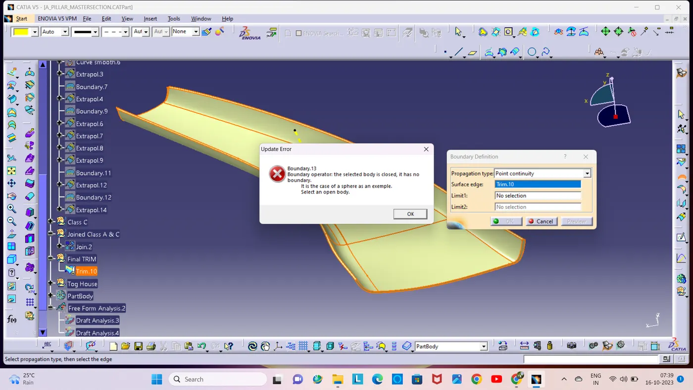
Solid part:
A solid part is created using the closed surface command on a trimmed surface.
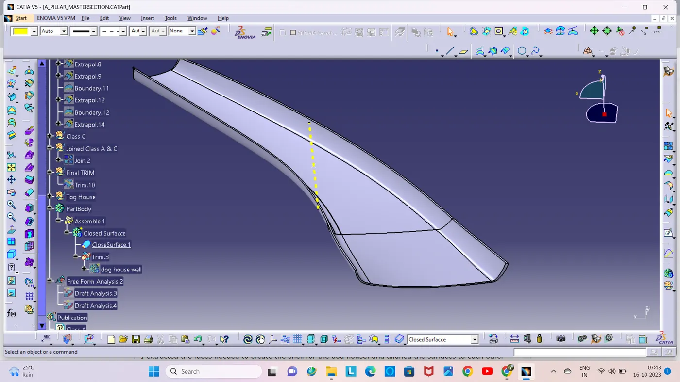
DOG HOUSE:
A dog house is an engineering feature used in plastic design. Dog houses are used as a supporting feature. Sometimes other engineering features like snaps, locators, screw bosses etc. are fitted to them to increase their strength.
Doghouses are subjected to draft analysis to prevent component breakage during ejection from the mold cavity. The dog house and other engineering components are built on the B-surface.
Dog houses are designed to avoid the sink mark created by screw bosses on Class-A surfaces and to solve length problems when providing screw bosses that need to be attached to other components.
Dog creation:
To create the dog house on the B-side, I extract the lines on the master section and create a plane to extract the lines about the master section.
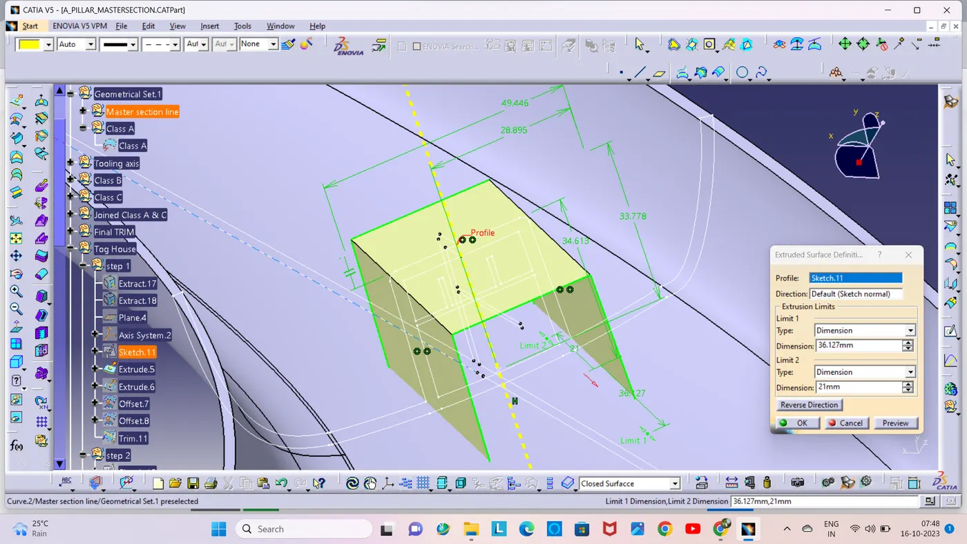
I extracted the faces needed to create the shell for the dog house, and aligned the surfaces to each other according to the dimensions of the master section.
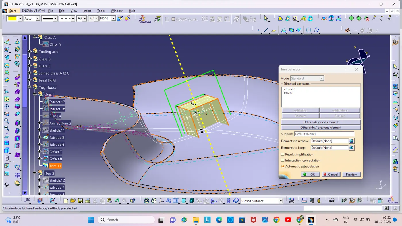
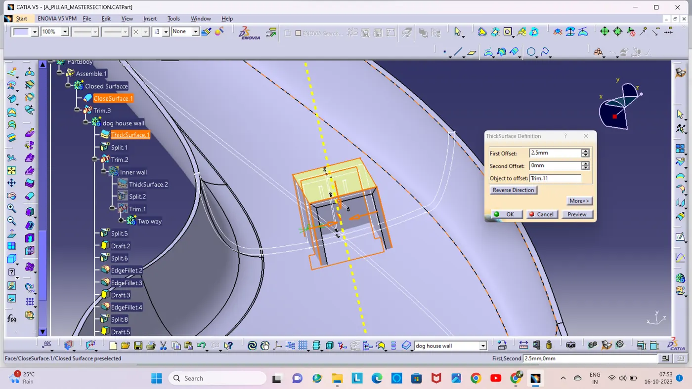
I use the thicken command to make it 2mm thicken in the shell. After thickening the surface, i gave the inside surface of the dog house a degree of draft.
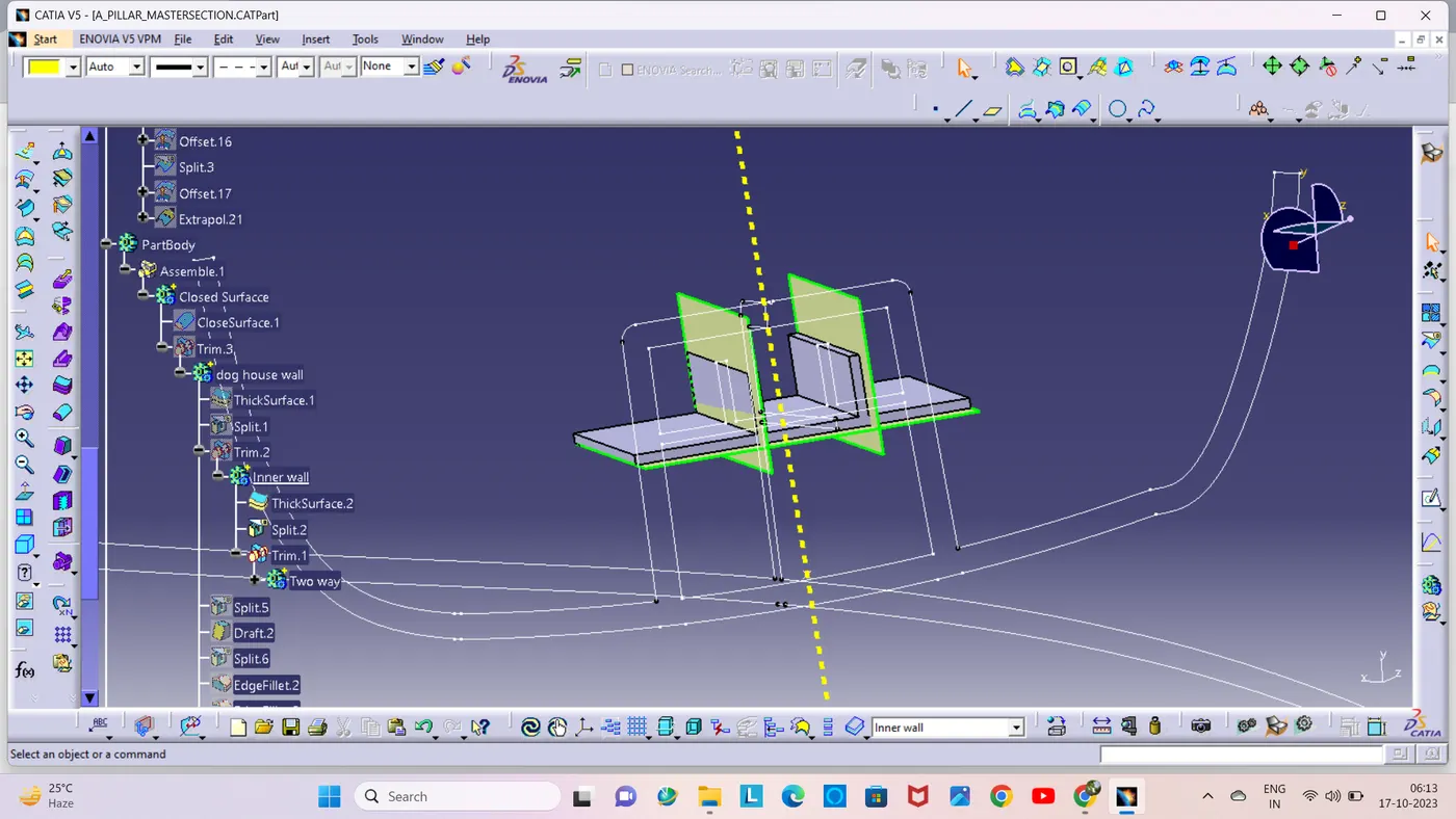
I created the base and way ribs of the two way ribs about the dimensions of the master section and gave a draft angle of 0.5 degrees to the base and ribs.
A cutout should be provided at the bottom of the dog house. To give the bottom cutout, I extracted the surface and offset it out by 1mm (the bottom cutout should be 40% of the thickness of the dog house). I extract the solid part surface and trim it by the offset of the inner surface, offset it by 5 mm in the upward direction.
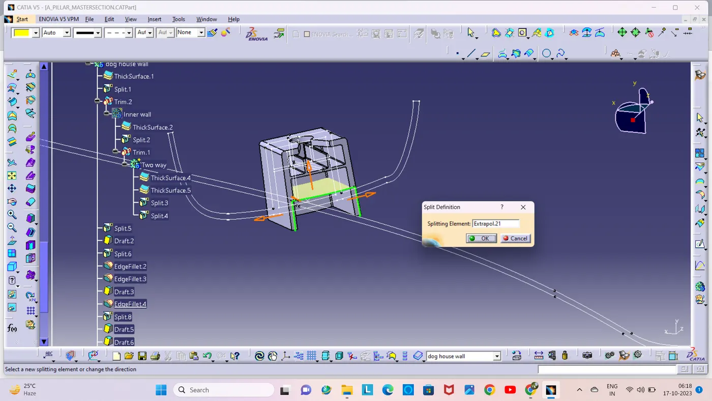
To trim with the offset of the inner surface.
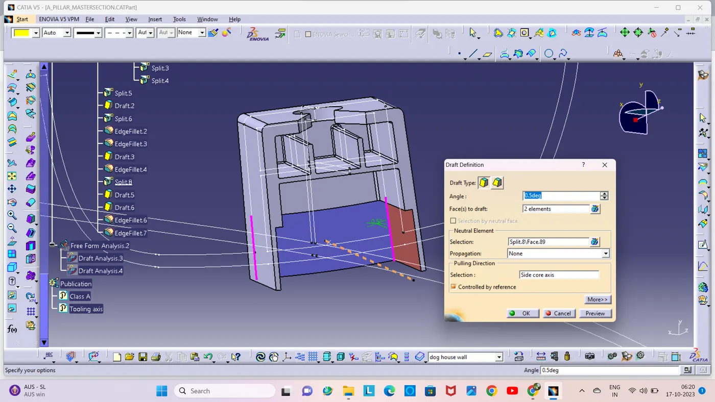
After trimming the bottom cutout surface, I split the surface from the solid shell of the dog house. I gave a 0.5deg draft angle to the bottom area concerning to the side core axis.
I created a sketch of the top surface of the dog house, then used the extrude command on that sketch, and then used the split command to remove the extrude surface inside the solid.
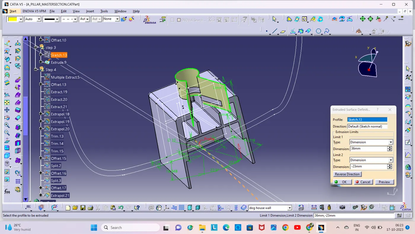
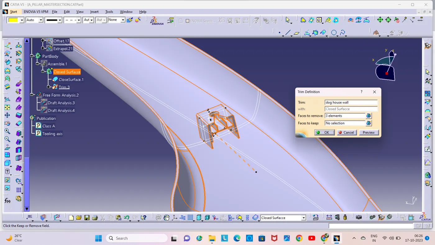
Then I gave a draft angle of 0.5 degrees. I added the dog house to the main body using the union trim command.
Draft Analysis:
Draft analysis is conducted to ensure that all the surfaces maintain the minimum draft angle.
The draft angle of the solid part of A pillar is 3deg, some surfaces are not properly cleared at 3deg draft angle.
I show minimal draft areas.
Class A surface is given a draft of 3 degrees.
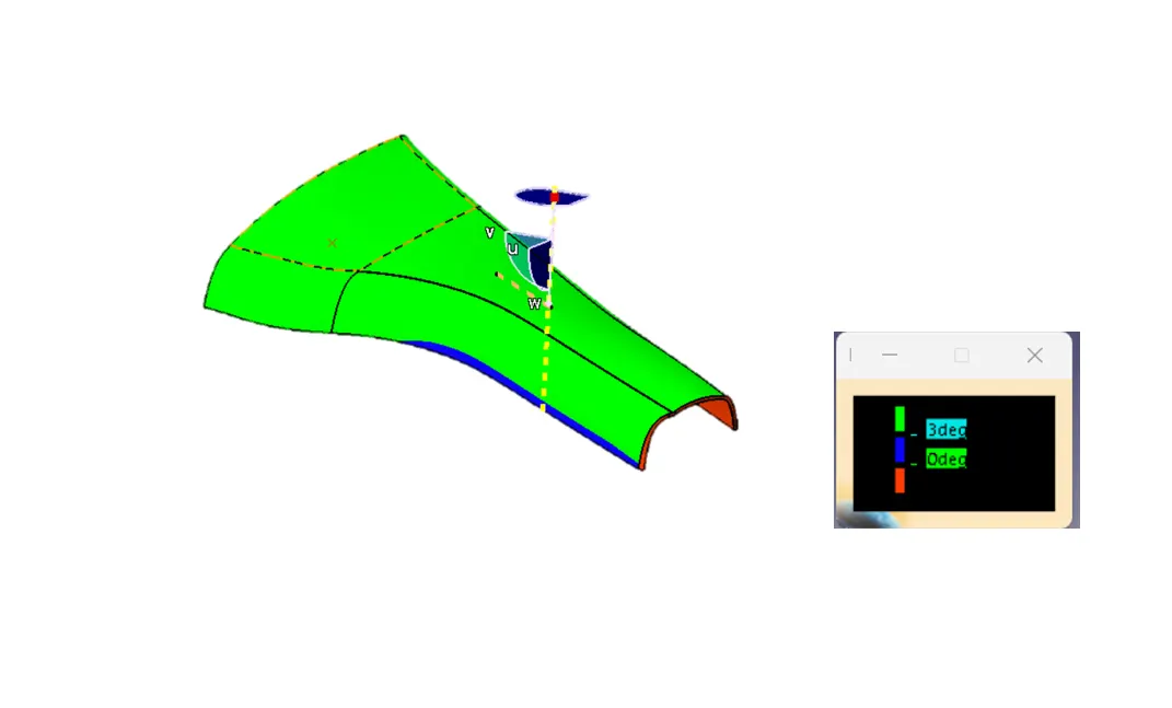
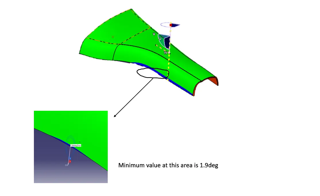
Class B surface is given a draft of 3 degrees
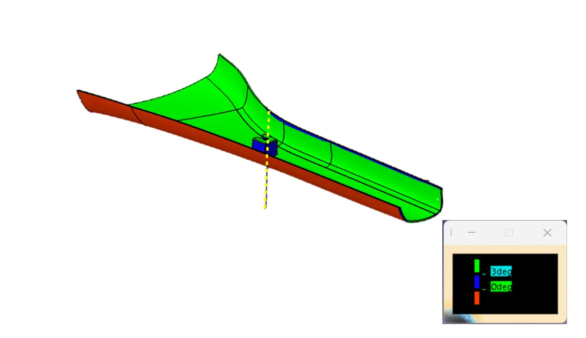
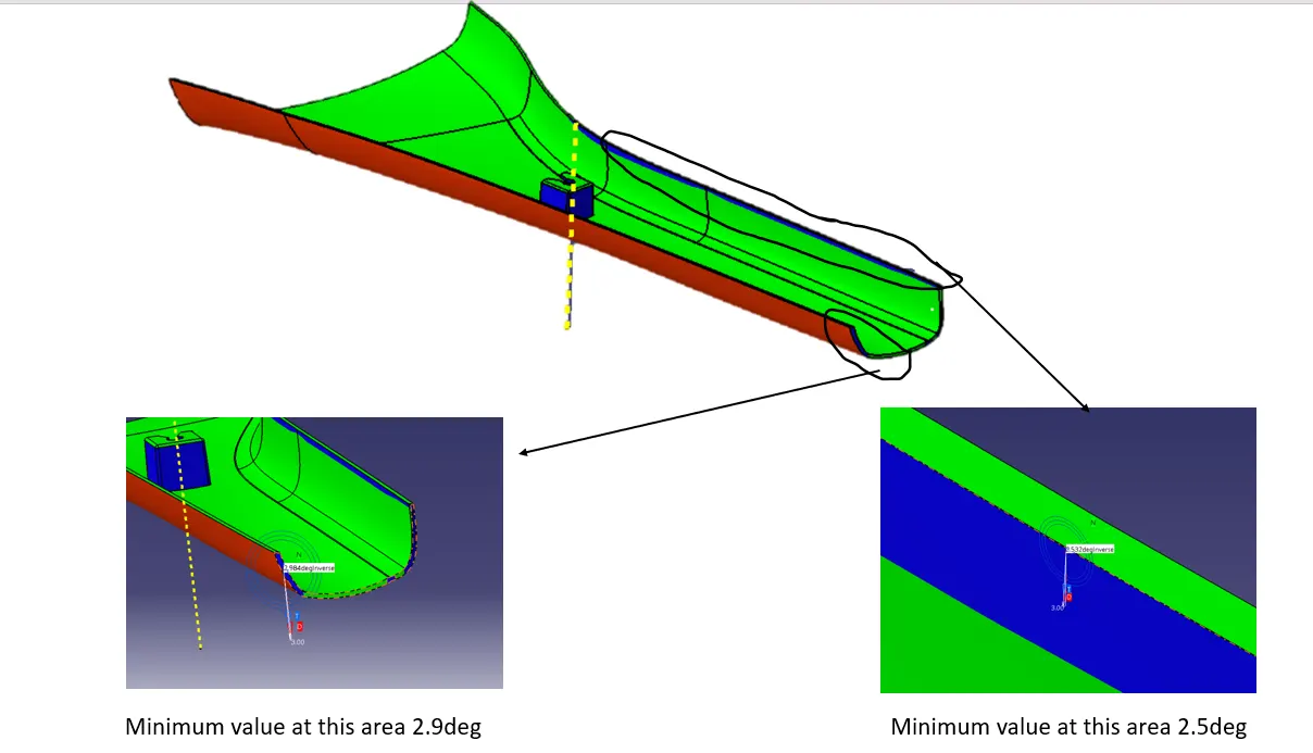
Draft analysis for outer surface of dog house:
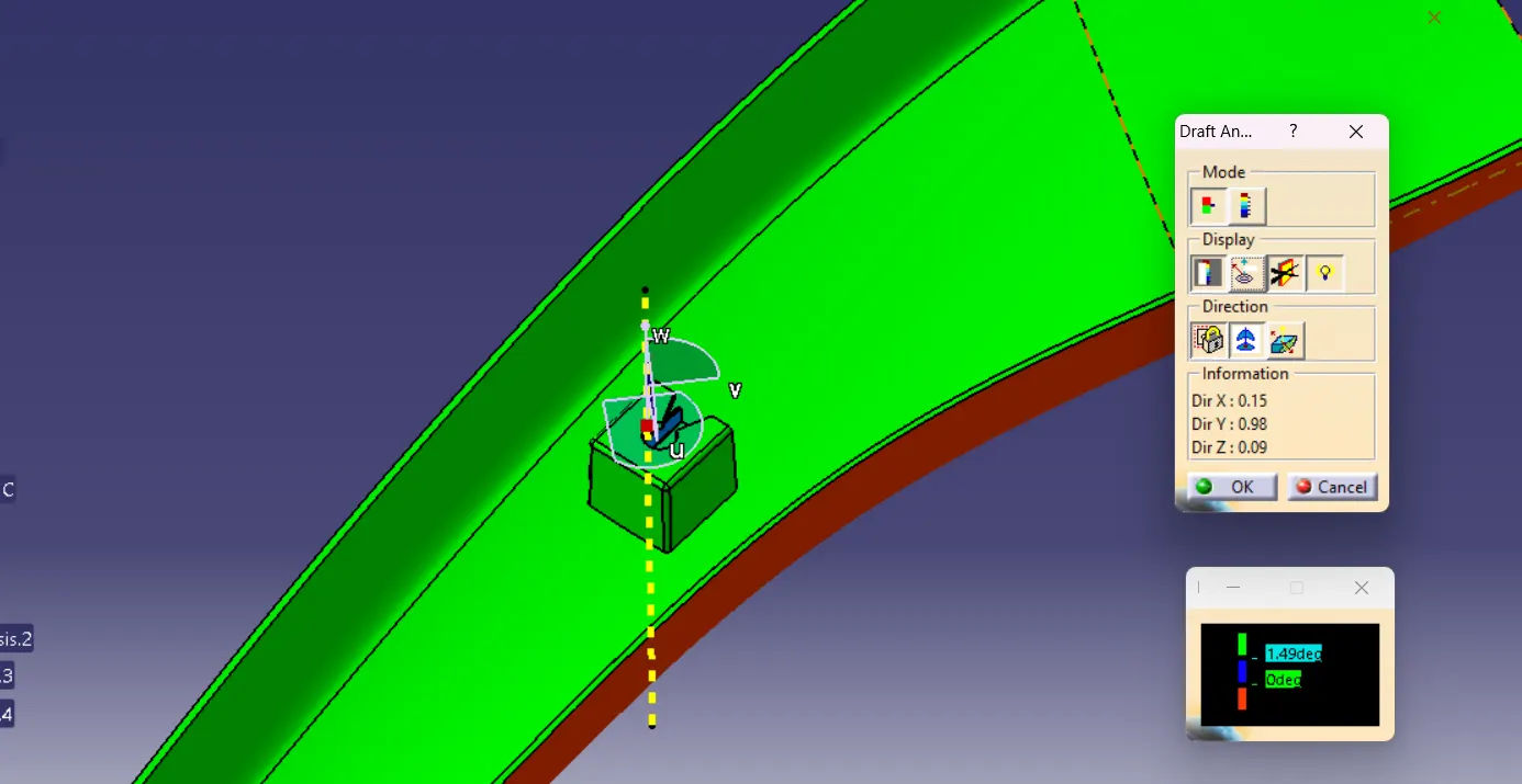
Draft analysis for inner surface of dog house:
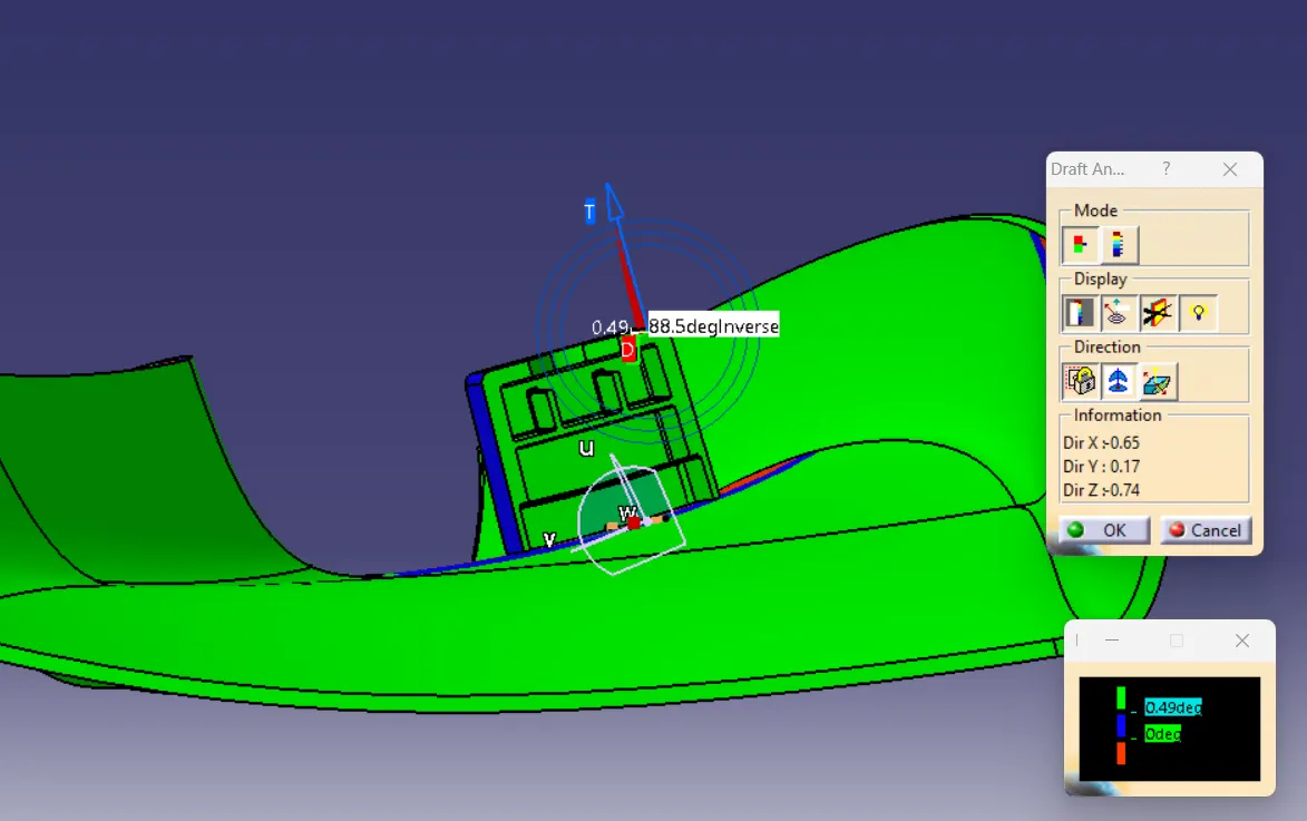
Different views: