Week 11 - Project - A pillar Design with Master Section
Objective:
The main objective of this project is to create the A Pillar Design with the master section given as the intersection sketch with the Class A surface and create the tooling axis and perform the Draft analysis for the final solid part.
A - Pillar Design
Class_A_Surface:
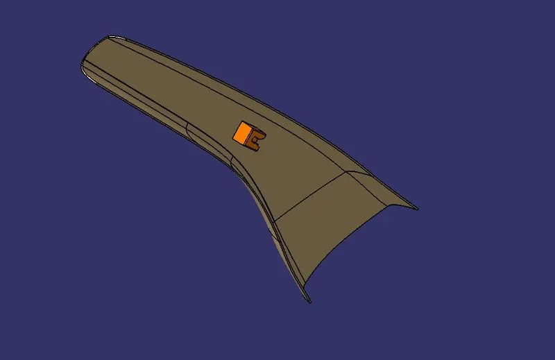
Class A surface refers to those surfaces which are VISIBLE and abide by the physical meaning, of a product. This classification is primarily used in the automotive and increasingly in consumer goods (toothbrushes, PalmPCs, mobile phones, washing machines, toilet lids, etc.).
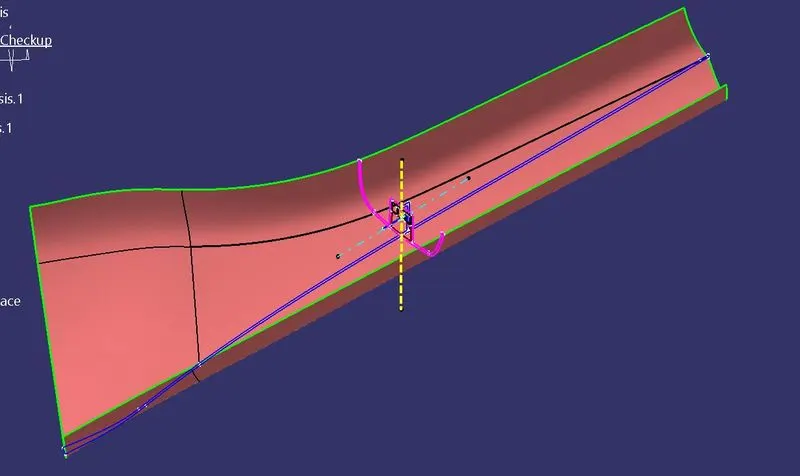
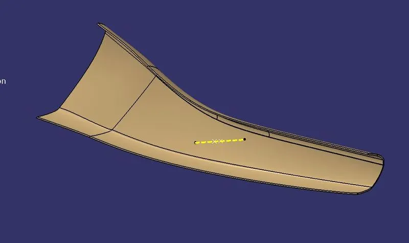
The above A_Surface is the source part for creating the B and C surface in this part component. And also the master sections are given for our reference to create this part.
Check for continuity of the given surface using Join or Boundary commands. If there is no errors in it, then we'll go with the next B_Surface creation.
Tooling_Axis:
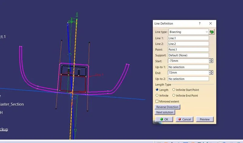
First we'll check the draft analysis for the A_Surface by using the tooling axis. For creating the tooling axis I'm using the master sections on the given part sile. Here I'm using the Bisecting method to create the tooling axis line.
Draft Analysis:
After creatig all the surfaces we can do the draft analysis for that. In plastic design, the draft analysis or angle that is considered in the OEMs is 3 degree.
A_Surface:
First we'll do the analysis for Class_A_surface. First we want to unhide class_A_Surface. Then go to Insert-> Analysis-> Feature Draft Analysis. Sometimes it'll some error for give material to this. We can make the part as material by using the material option. Then we'll do the draft analysis. For doing that we using the compass tool on the draft analysis window to place on the tooling axis and then lock it.
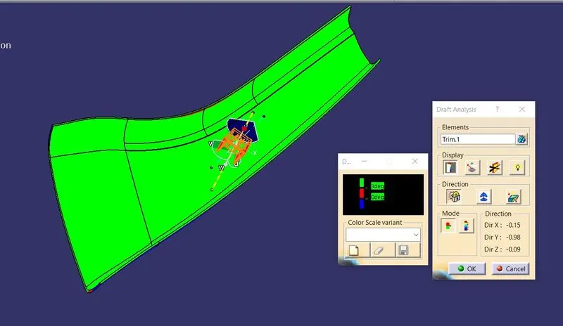
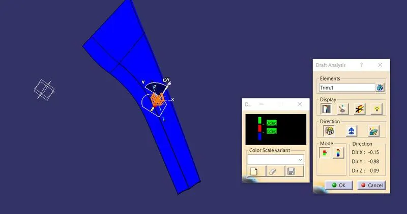
By clicking on the surface, the whole part turned into green color. If blue was visible that meant that the analysis was inversely done so just by flipping the direction, draft analysis.
The green region shows the part which is toolable or produceable by the molding machine and the draft angle is 3degree.
Blue color region states that the part can be allowed in some OEMs but still need to be improved for the other OEMs as the draft angle is more than 3 degrees.
Red color which is not there in this case states that the draft angle is less than 3 degree and cannot be produced or if produced would be faulty.
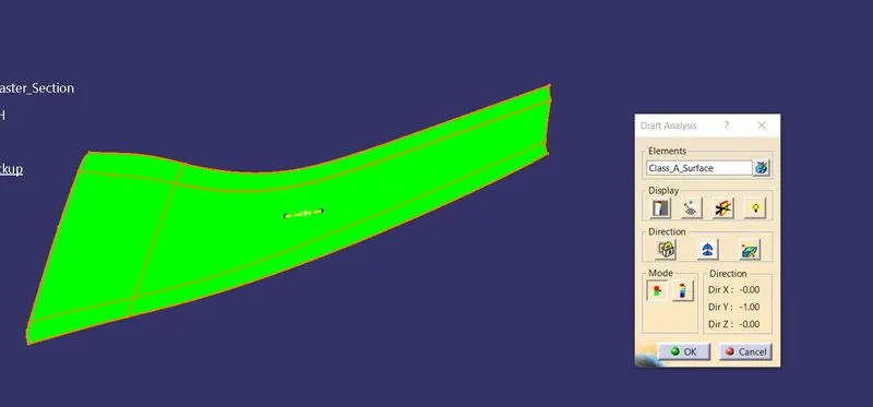
Hence our A_Surface satisfies the draft analysis, so that we can move to create the B_Surface creation.
Class_B_Surface:
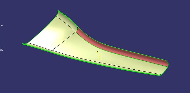
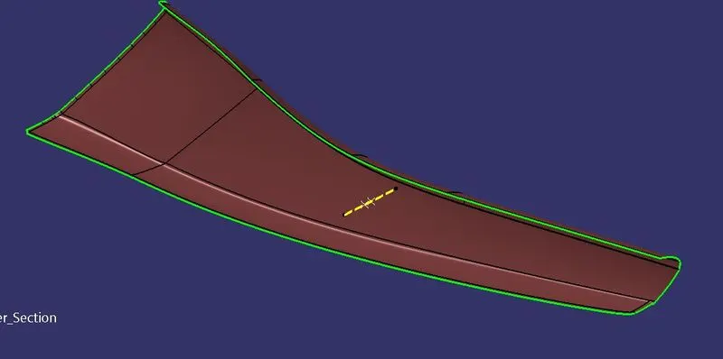
After creating the tooling axis we want to create the B_Surface offset to 2.5 mm. So we want to offset these surface in inward direction.First, offset the surface to 2.5mm, some errors may occur and some parts got removed. Click keep all sub-elements. And use fill, sweep, boundary, extrapolate, and trim commands to close the patches. Then join all together to create the Class_B_Surface.
Offset_Surface:
Final_Class_B:
Class_C_Surface:
For creating the C_Surface I'm using the boundary of the A_Surface. Using the boundary of A_Surface we'll use the sweep tool to give extended surface creation on the A_Surface.
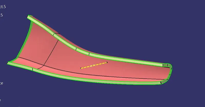
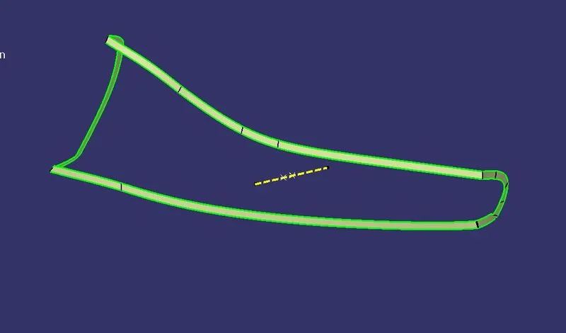
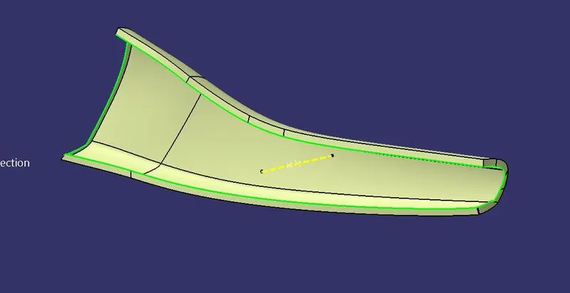
After created the C_Surface, then we can join with the A_surface, it was shown below,
Final output:
After creating B_surface and the joined A&C Surface, we can trim them to get the closed profile of the surface.
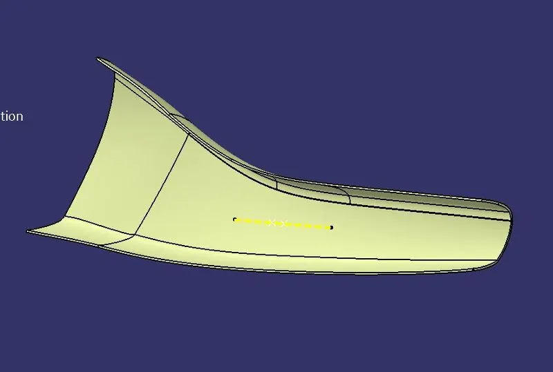
Closed Surface:
After creating final part we'll make it to solid by using the close surface tool in the part design workbench. Then finally we can get this output.
DOG HOUSE
Dog house is an engineering feature used in plastic design. Dog houses are used as support feature. Sometimes other engineering features like snaps, locators, screw bosses are mounted on them to increase their strength.
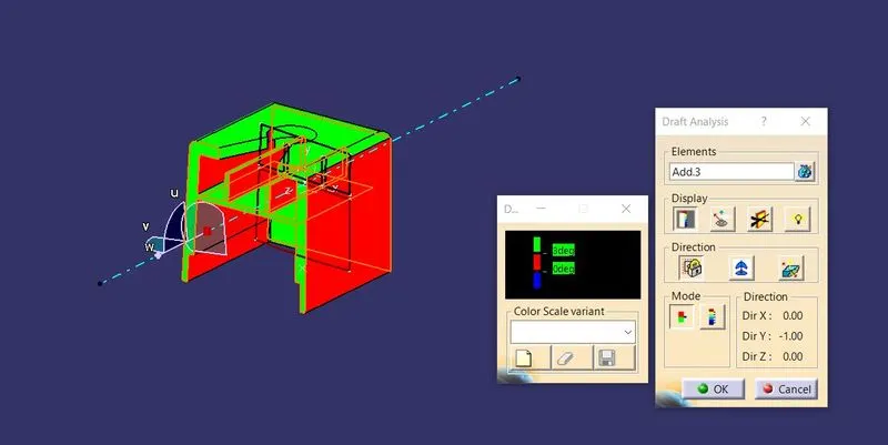
Dog houses are subjected to draft analysis to prevent breakage of the component during ejection from the mould cavity. Dog house and other engineering components are built on the B-surface
- Dog houses are designed to avoid SINK MARK created on the CLASS-A surface by screw bosses and to solve the length issues when giving screw bosses which need to be assembled to other components.
- It is also useful when perpendicular screw bosses are required on the part to the tooling direction.
The above reference drawing file is given for to creating the dog house,
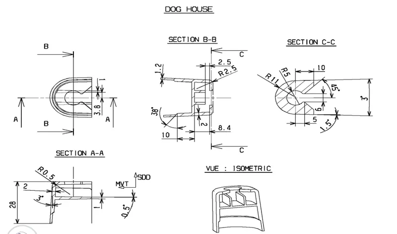
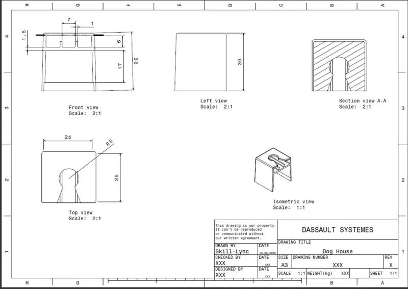
For creating this dog house wee can use the master sections to check withe the surface creation on the final part surface.
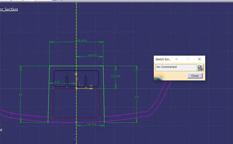
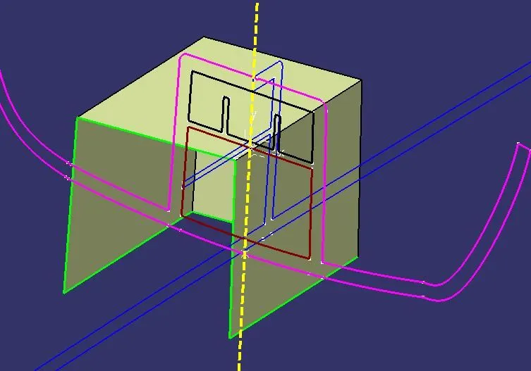
We have the reference of the master section intersect lines for creating the dog house, Specifically we want to draw the sketch on these areas to create the dog house by using the surface workbench.
First, I created one axis on that area of the intersected mastersections, it was shown below,
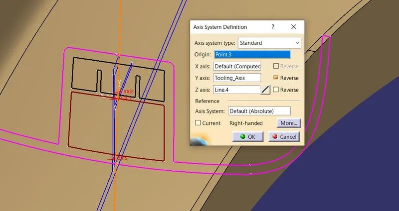
The normal walls of the dog house is created in the area,
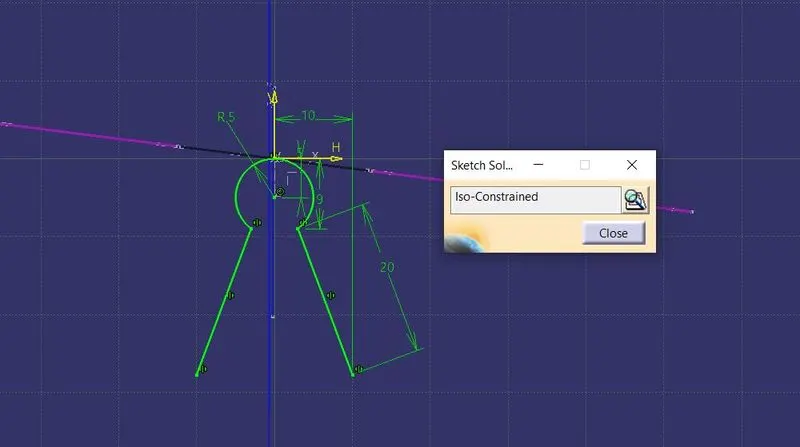
Top_Circle_Cutout:
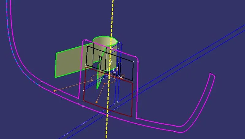
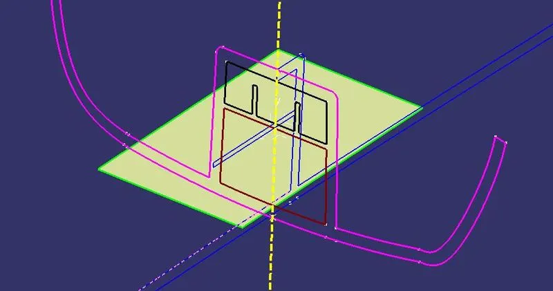
Rib Base:
In this base I'm just using the mastersections lines whichwill be extract seperately and made the extrude and also made the thicken command to get the final rib base on the dog house.
Ribs:
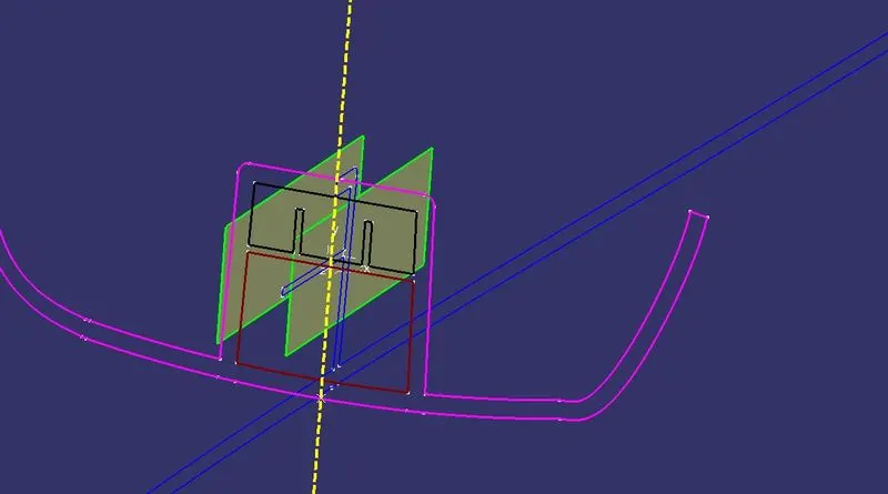
For creating the ribs also I'm using the same method which was used on the above rib base, it was shown below,
The Bottom C_Side_Dog_House:
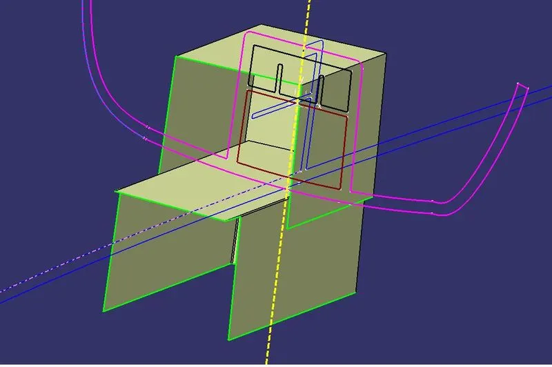
I'm using the wall surface and using the surface options to offset it get the final output surface for cutting the Bottom surface of the Dog house.
Final Dog House:
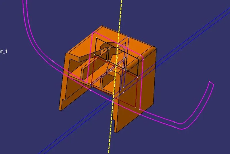
After creating all the surfaces we can thicken it by using the thicken command in the part workbench. And then we can use the boolean operations to add the seperated parts to the one part.
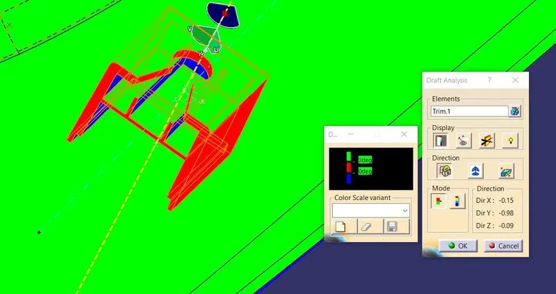
Draft Analysis for Dog House:
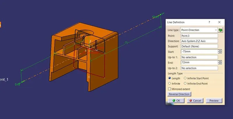
For analyse the dog house drafting, we are going to make another one side core axis for this Dog house. I'm using the line to creating the axis in the required direction, it was shown below.
Side Core Axis:
Dog_House-Draft Analysis:
Final Output of the Component:
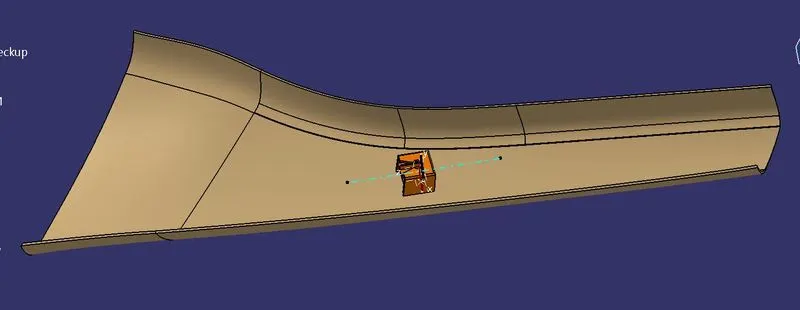
Then we can use the boolean opeations to add this dog house with the Final part component.
Checking the Mastersections with our intersecting lines:
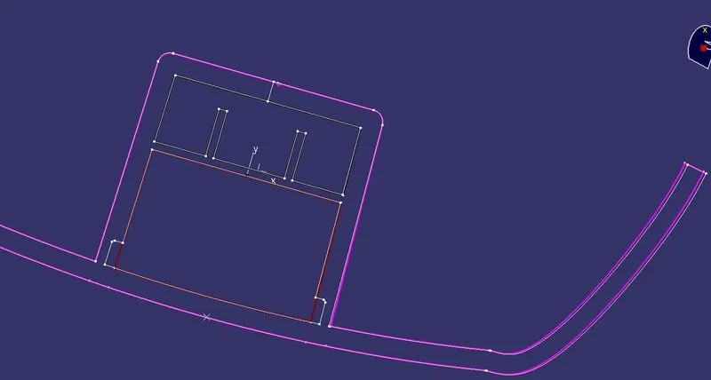
Here I'm creating the intersecting lines with the surface with the Axis planes to get the final output, then we can check it with the Master sections.
The side View:
Front intersecting View:
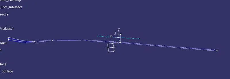
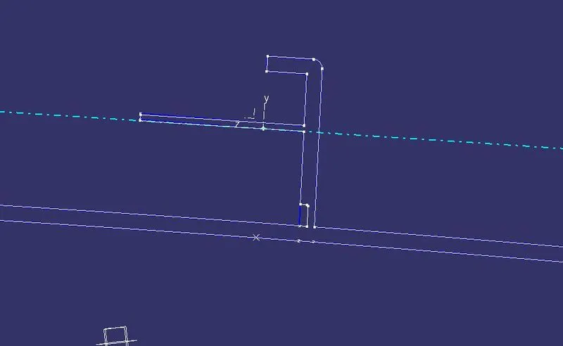
Finally, our output surface matches with the Master section lines, So we can use this part as an output.
Draft Analysis For Final Output:
3D View Orientations:
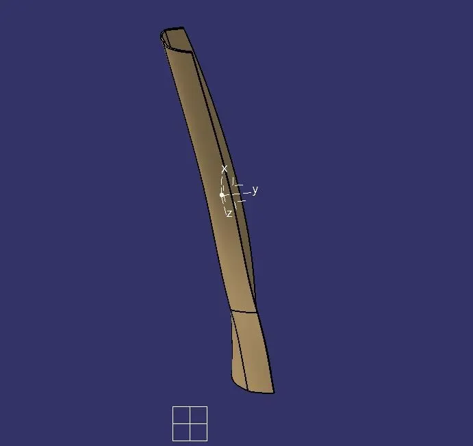
Front View:
Top View:
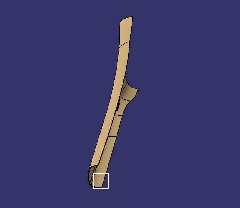
Side View:
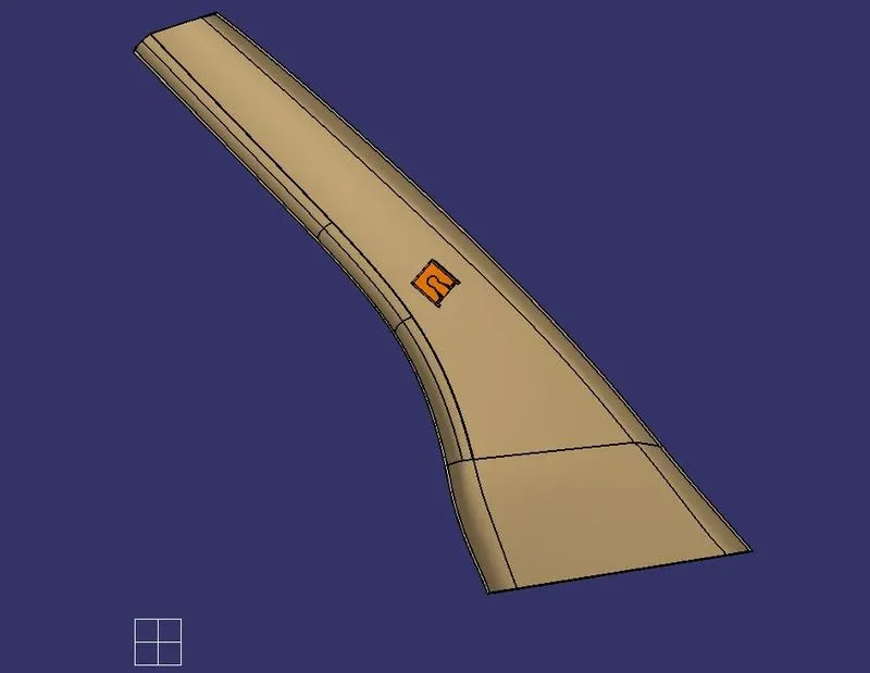
Isometric View:
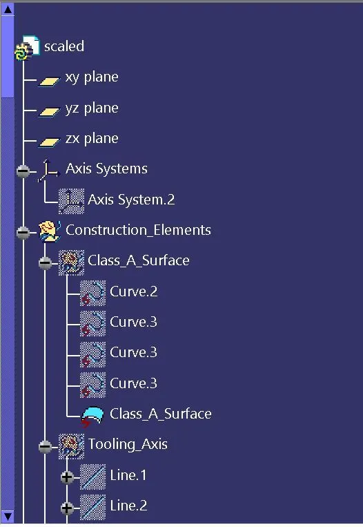
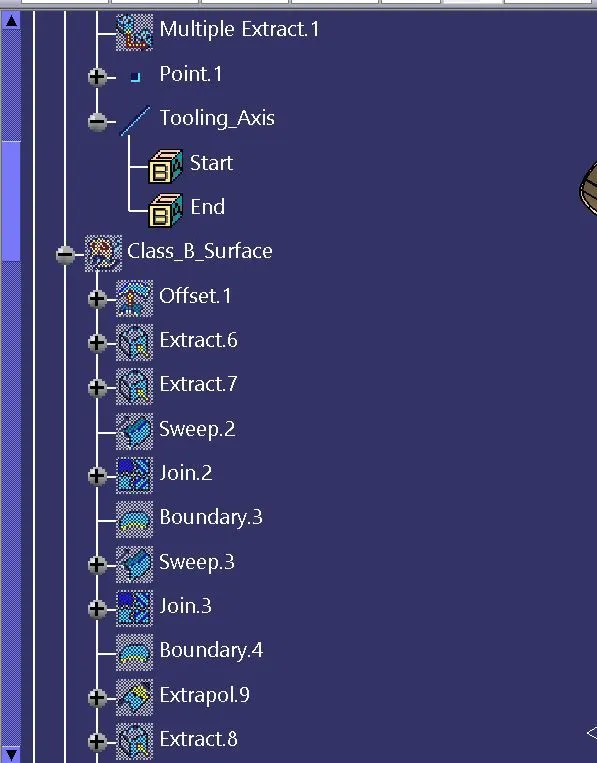
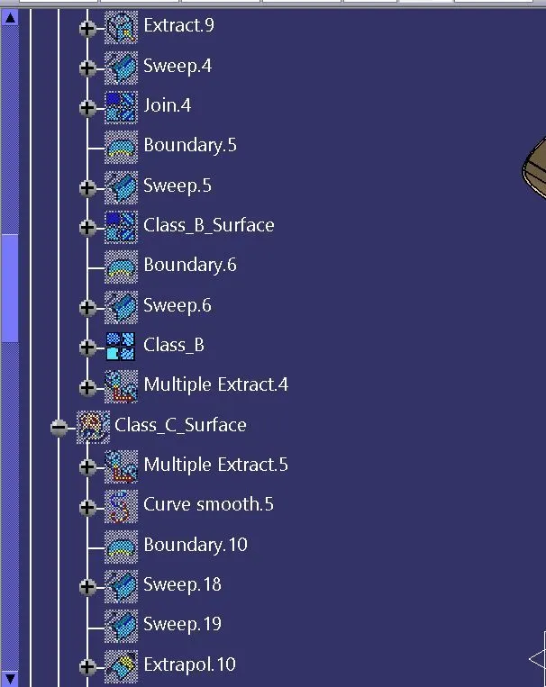
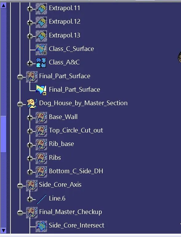
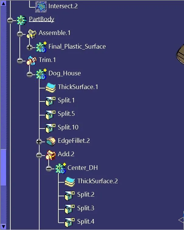
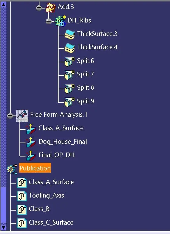
Tree Structure: