Week 11 - Project - A pillar Design with Master Section
A PILLAR DESIGN WITH MASTER SECTION
OBJECTIVE: To create the A-Pillar Plastic component from the given Class A Surface using the Master Section and also creating the Dog house.
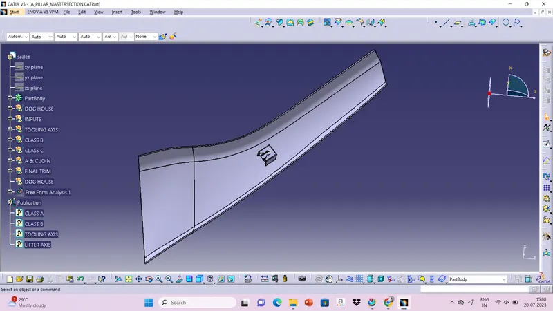
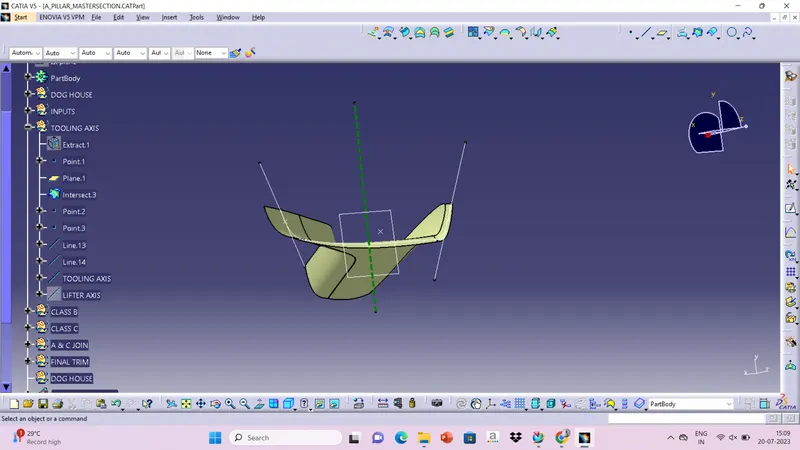
CREATING TOOLING AXIS
- Tooling axis is created using the bisecting method.
- Extracted the base flat surface of class A and created a reference point.
- Intersected the class A along the xy plane created and drawn 2 lines along the sloped faces.
- Then created a bisecting line for the 2 lines through the reference point and created the tooling axis.
- Published the tooling axis.
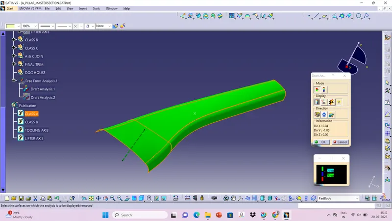
DRAFT ANALYSIS ON CLASS A SURFACE
- Changed the view mode to Material mode.
- Insert>Analysis>Feature draft analysis
- Activated the compass and then by dragging the red point, placed the compass along the tooling axis and locked it.
- Clicked on the part and analysed the draft angle of component.
- Considered the min. draft angle as 3 degree.
- The green colour area shows that the component satisfies the given draft angle.
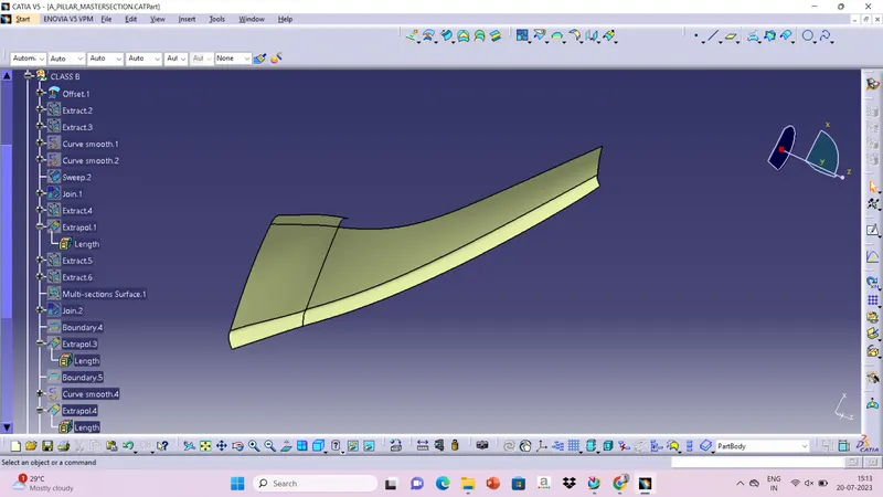
CREATING CLASS B SURFACE
- To create class B surface, the whole class A surface is offseted by 2.5 mm.
- One patch was missing.
- So i used the sweep command to fix the missing patch.
- Then i used the Join command to create a complete class B surface.
- All the edges were extrapolated to trim it with the A&C join.
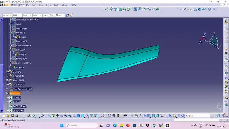
CREATION OF CLASS C SURFACE
- Using boundary command created separate boundaries on the edges of the class A surface and used the SWEEP command to create class C.
- 3 degree draft were given to the edges which were perpendicular to the tooling axis.
- And sweep command using the reference surface were given to the other edges.
- Then extrapolated the edges and trimed them together to form a complete class C surface.
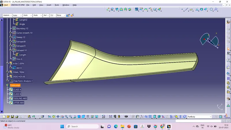
- Then joined the class A and class C surafces together.
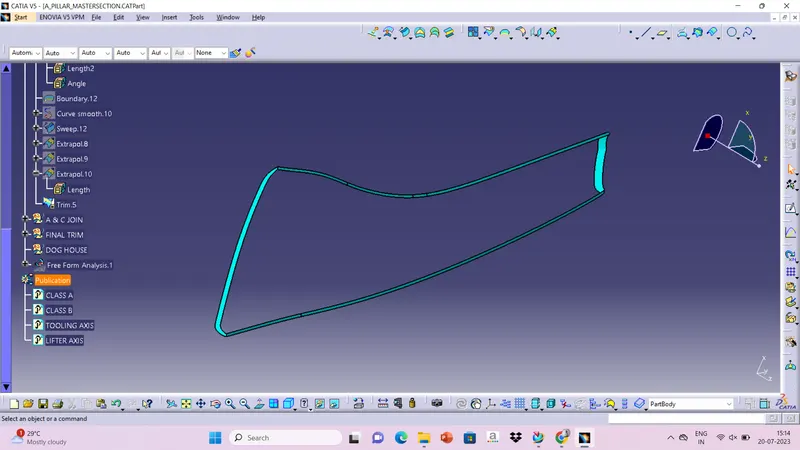
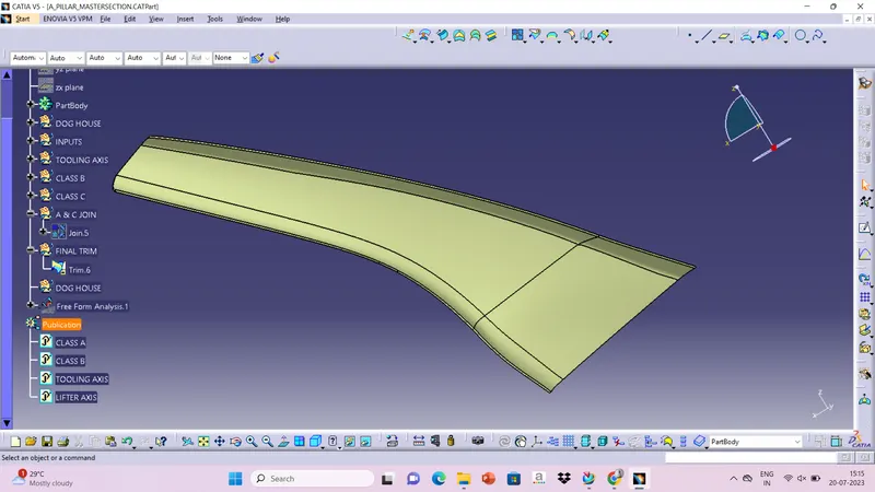
- After that this class A+C join were trimmed with the class B surface to get a closed component.
- Used the boundary command to check whether the component has any open boundaries or not.
- Then in the part design workbench used the CLOSE SURFACE command to create a solid out of the component.
CREATING DOG HOUSE
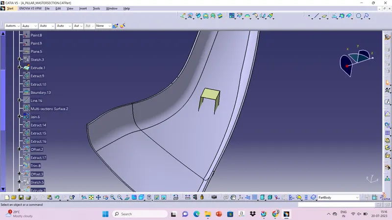
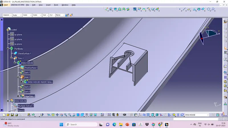
- Using the Master section as a reference created the dog house sketch.
- Extruded the sketch to create dog house walls and using multi section command closed the rear side of dog house.
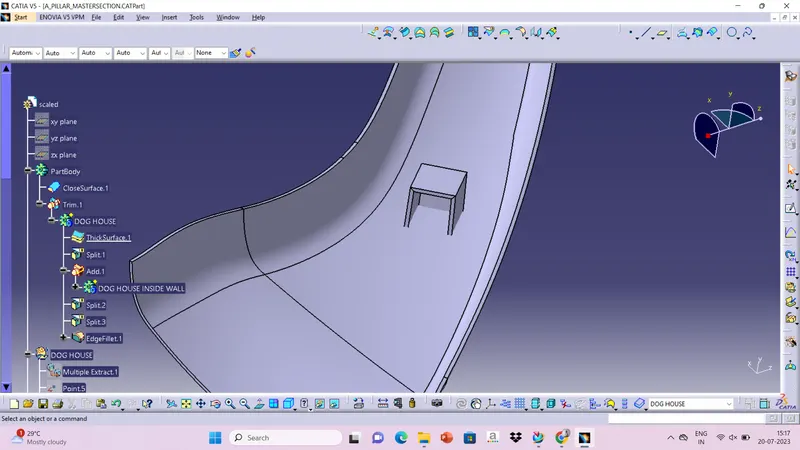
- Under the part workbench using Thicken commad thickened the walls.
- Draft with an angle of 3 degree is given with respect to the Main Tooling Axis.
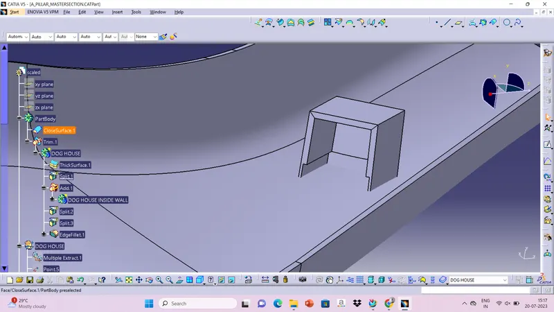
- A base is extracted from class A and offseted it and with other offseted surfaces and trim command created a base shape to be cut from the dog house.
- Using the split command in part workbench the material is removed.
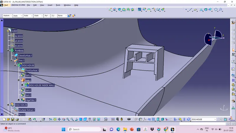
- Using the Master Section sketch for the inner walls of the doghouse is created.
- Then extruded and thickened it and then using boolean operation assembled it to the doghouse body.
- Draft is also given to the inner walls of the dog house based on a side core tooling axis created.
- Then necessary fillets were given.
- Then union trimed the dog house with the main solid component.
DRAFT ANALYSIS ON FINAL SOLID COMPONENT
- Draft analysis was performed on the final component in the same method which i used for the draft analysis of class A surface.
- And also draft analysis was performed on the Dog house body based on side core tooling axis.