Week 11 - Project - A pillar Design with Master Section
AIM :-
To create a pillar Design and engineering feature of doghouse with the help of Master Section, that is provided with the Cat file in the Classs A surface.
Points to ensure:
- In Tree StructureEnsure using the surface command.
- Use closed body command to create the solids
- Rename the geometrical set properly.
Output Required in a ppt :-
- Picture of the sketches with Sketch solving status’s geometry tab
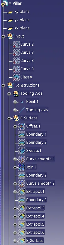
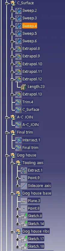
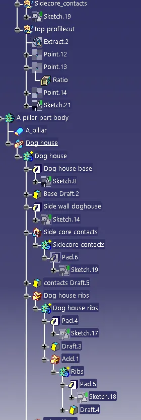
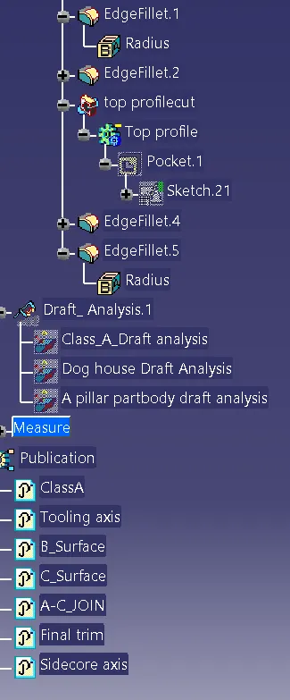
- Picture of the Detailed tree structure.
- Picture of the 3D CAD
- Create closed body
- Create a tooling axis and follow design rules.
- Follow the Master section to create a flange
- Follow the master section for thickness and to create the Closed volume.
- Follow the master section to create Attachment features
- The thickness of the Plastic to be 2.5 mm.
Objective :
- Create the required Tooling axis by using master section
- Design the Class-B and Class-C surfaces and close all three surfaces.
- Design the Dog house and its internal parts as given Drafts and mater section sketch.
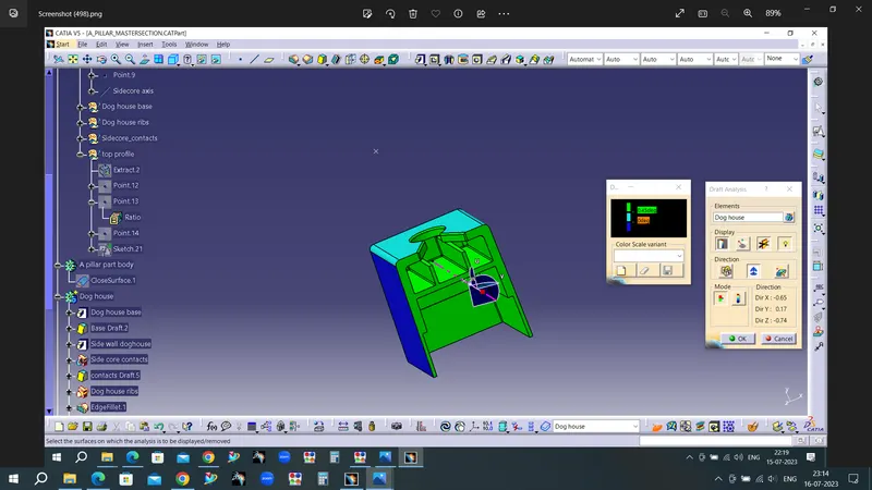
- Draft analysis for the final solid part and side core Draft analysis.
ROLE OF THE A-PILLAR:
A-Pillar is located on either side of your car’s front window (or windshield).
They also hold the hinges of front doors. A-pillars are normally made of steel alloys.
Besides being a supporting member, A-pillars are very crucial as far as safety is concerned. A-pillars usually carry a significant amount of load during a frontal collision or a rollover crash. So the larger the width or cross-section, the greater would be the strength but A-pillars always block the driver’s vision (create blind spots) to some extent that can be realized while driving. So, having that said, using thicker A-pillars can make the situation even worst. It might further lower the driver’s vision and raise a question about the vehicle’s and passenger’s safety.
Hence, the design of A-pillars must be optimized giving equal importance to both strength and the driver’s vision.
Firstly, we have to create the required Tooling-Axis for the given Class A Surface while meeting the requirements of the necessary Draft Angle & then perform the Draft-Analysis Operation on the Class A Surface itself.
After that, we have to create the required Class B & Class C Surfaces using which we have to make the Final Plastic Component and perform Draft Analysis on it.
MAIN REPORT:
Types of Surfaces and their importance for an Automotive Plastic Designer:
- Class A Surface:
Class A is an aesthetic surface with the highest quality finish. Most Class A Surfaces for an Automotive Component are made using 'Autodesk-Alias' based on the final Concept-Sketch.
All Class A surfaces should have 'Curvature-Continuity', meaning the continuity between the surfaces should share the same boundary. It is taken as a reference by the Automotive Plastic Designer to create 'Class B' and 'Class C' Surfaces.
- Class B Surface:
The Class B Surface resides below the Class A Surface at a certain thickness. It is created using Engineering Principles that consist of all the necessary features such as Ribs, Bosses, Snaps, etc. This surface isn't visible to the observer from the outside.
- Class C Surface:
The Class C Surface is the surface created between the Class A and Class B surfaces to join them with each other.
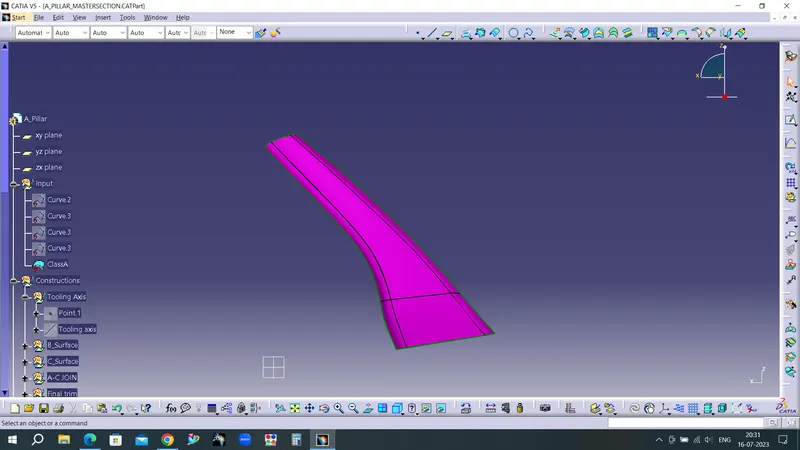
Now, we will begin by checking the State of Connectivity for the Class A Surface and ensure that there are no gaps between the surfaces as all the surfaces should be joined well together with each other and shouldn't consist of any discontinuities between them.
Our Class A Surface:
Procedure for creating the tooling axis
Tooling axis represents the opening and closing of the mold core and cavity during the manufacturing of the components. A plastic product designer should consider the best tooling direction to cutdown the cost of the component very less.
Method opted for creating tooling axis for the door handle
- Check the best tooling direction for the given surface.
- We can find out the best tooling direction by cross checking all the three axes.
- Here we can find out that the best tooling direction for the pumper class-A surface is along Y-axis direction.
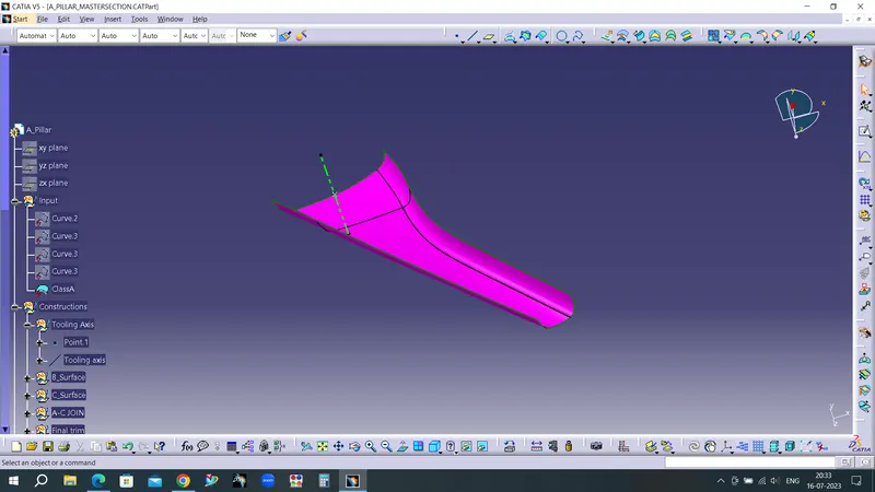
Creating tooling axis
We should create a Dummy tooling axis first by creating point and line.
Select the curve in existing class A surface and create a dummy tooling axis for reference.Highlighted green colour is tooling axis.
Draft analysis for the given CLASS-A surface
The Draft Analysis is a command enables you to detect if the part you drafted will be easily removed. This type of analysis is performed based on colour ranges identifying zones on the analysed element where the deviation from the draft direction at any point, corresponds to specified values.
Draft analysis is done after determining the tooling axis, draft analysis is used to check whether the minimum draft (3 degrees) is maintained or not.
- Procedure for performing the draft analysis are as follows
- Change the view mode of the component to be in customized parameter mode and then select the shading mode as materials.
- Then open the featured draft analysis tool from the insert menu.
- Then click on use the compass to define the current drafting direction without activation the compass and then activate the compass in the dialogue box drag and align the compass on the Tooling axis.
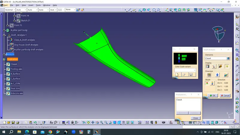
- Then lock the draft direction and perform draft analysis by clicking on the component
- The green colour shows the positive daft tooling direction and the given surface passes the draft analysis.
- Click on the analysis under the running point to check the draft analysis on the individual faces. It shows how much draft on specific points when we move the cursor point.
SURFACE-B CREATION
Class-B surface means thickness of a part it is not visible and is inside part. In other words, Class-B surface is a surface below a certain thickness from the class-A surface. This is the surface that contains engineering aspects of a model.
- Offset the class-A surface to 2.5mm inward direction.
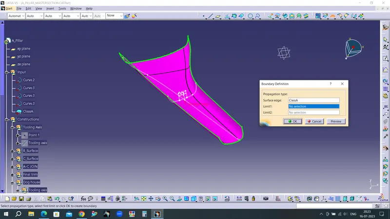
- After offset ,There will be some open patches in the fillet area ,Found an open patches as shown in below images.
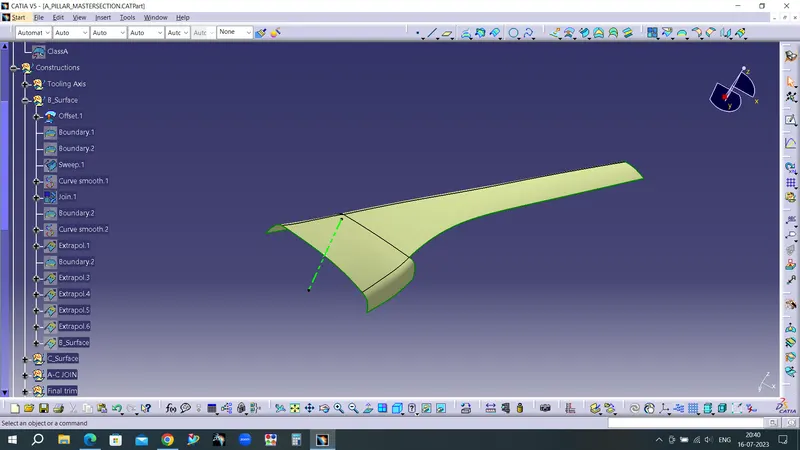
Class B Patch area
Procedure for rework on the patches and discontinuity of the offset surfaces using the features like Boundary, Sweep,extrapolate,Trim .
- I created boundary of the edges of the patches, to give as a sweep command's profile and guide curves to close the patch.
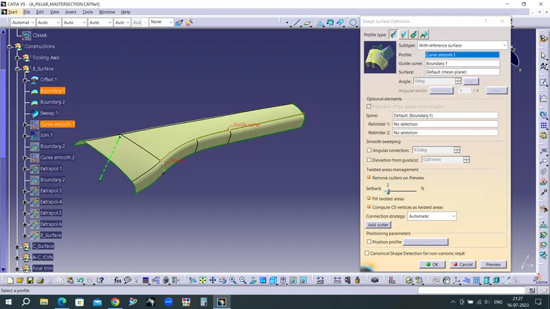
- After sweep , join the offsetted and sweep surfaces
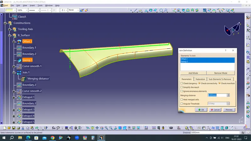
- Extrapolate the edges to extend and created the B Surface
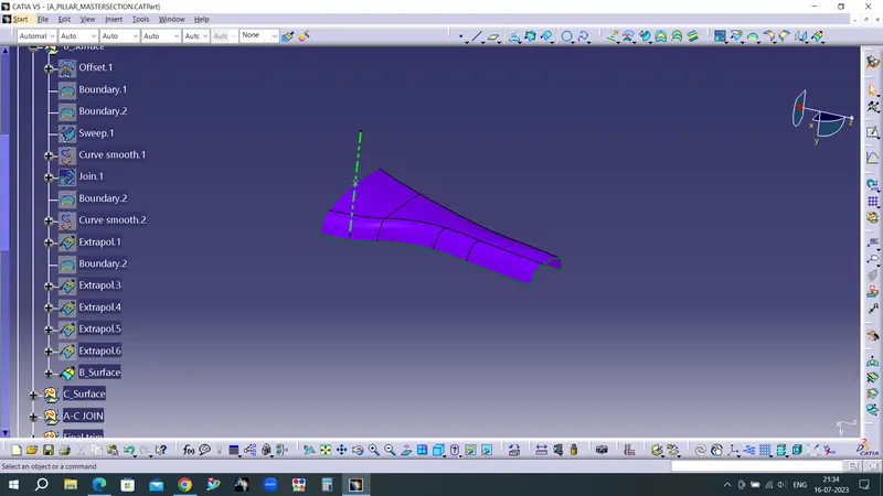
B Surface
Creation of C Surface
- Surface that joins class-A and class-B surfaces is class-C surface. Class C is often specified for interior surfaces not readily visible, surfaces that will be covered by another part when assembled.
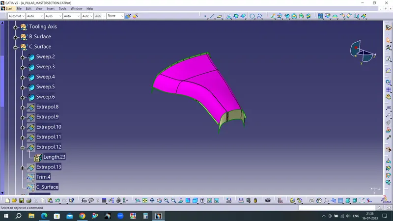
- Since it is a class-A surface with sharp corners, we cannot simply create the class-A boundary curve and sweep it at one shot.
- Hence, we need to create smaller boundary and then create sweep,Multi section surface.
- If the surface is perpendicular to the tooling axis we have to provide 3 degree draft with reference to the tooling direction.
Final C Surface
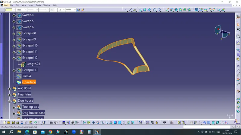
Creating the final surface
- First step is to join the CLASS-A surface with CLASS-C surface.
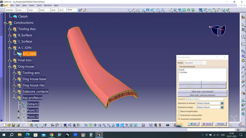
Final A-C JOIN
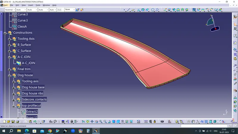
Final A-C&B trim
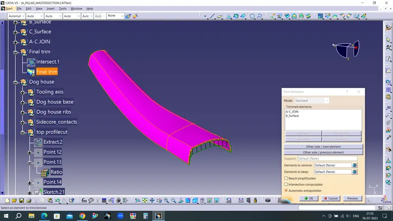
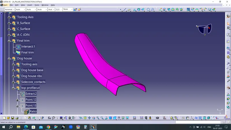
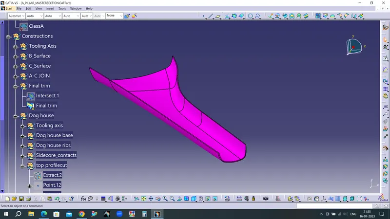
Draft analysis of A pillar part body
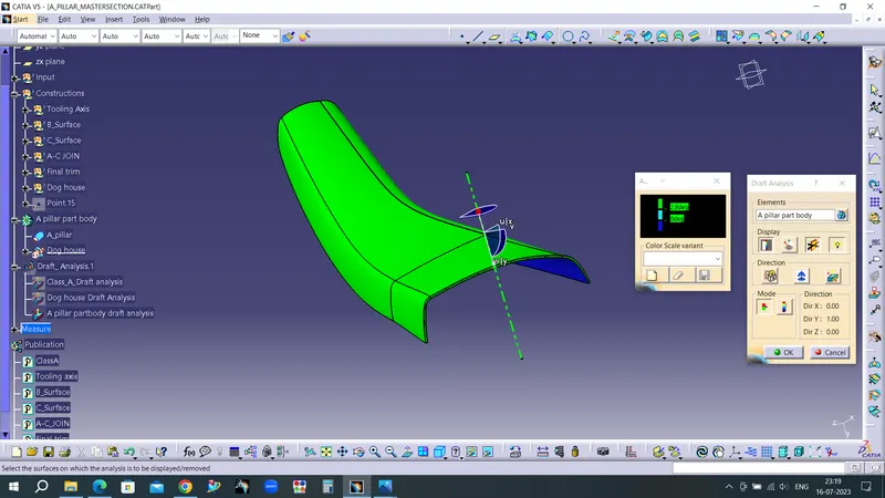
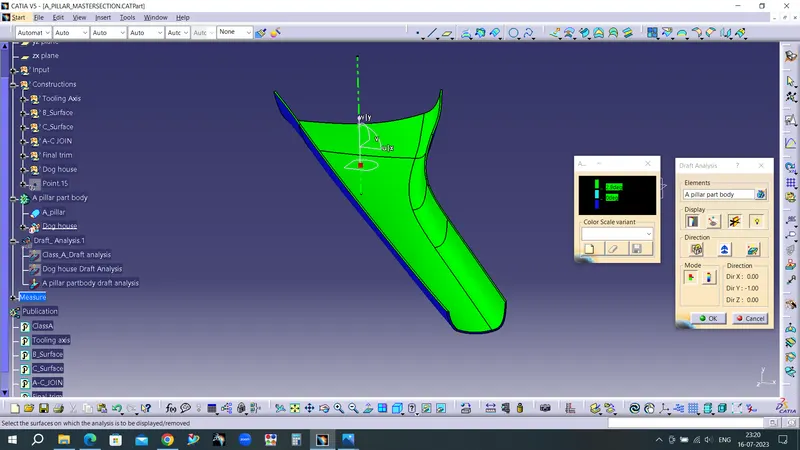
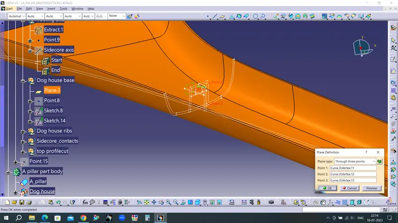
PROCEDURE TO CREATE THE ENGINEERING FEATURE- DOGHOUSE USING THE MASTER SECTION:-
- To create the dog house on the B-side, I extracted the lines on the master section and I create a plane to extract the lines concerning the master section.
Tooling Axis
Created Sidecore tooling axis by creating point with normal to the plane .
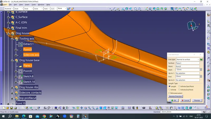
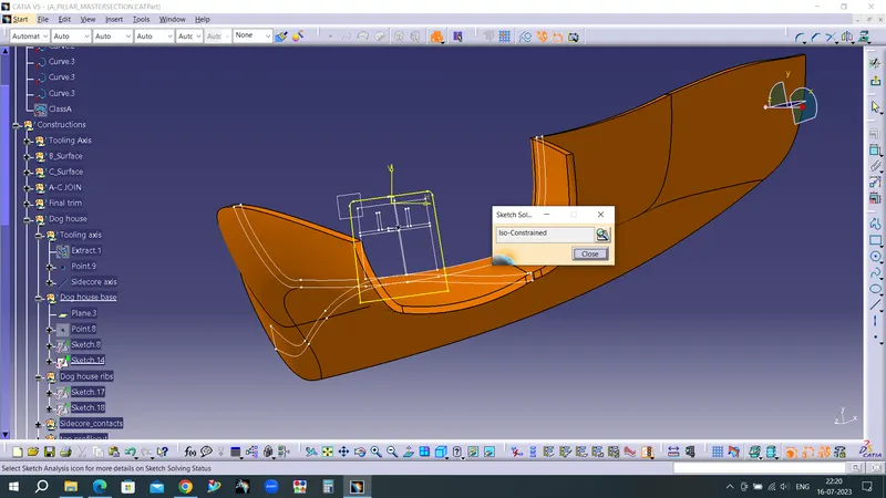
Dog house Sketch workbench
Sketch of outer base
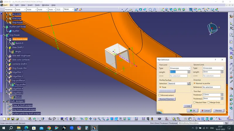
Part workbench of dog house base
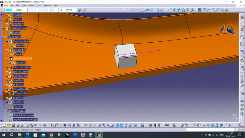
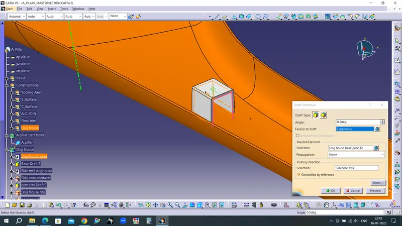
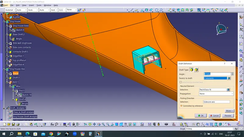
Applying draft to the inside walls
Sketch of ribs
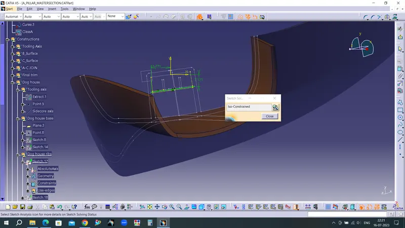
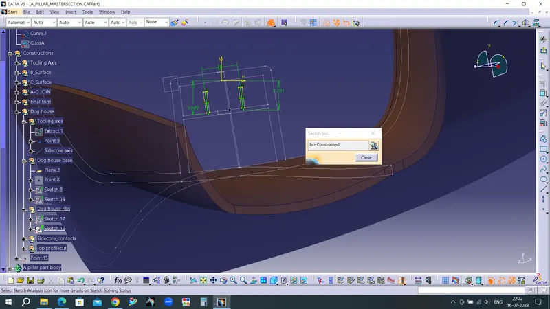
Part workbench of ribs
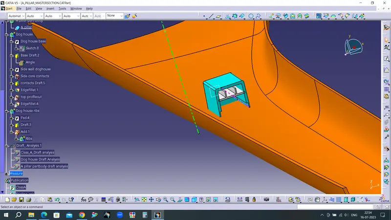
Appling drafts to ribs
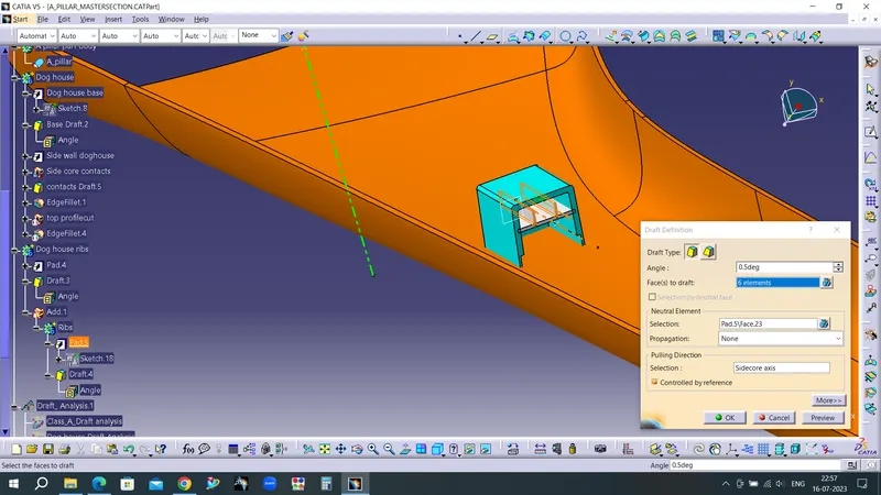
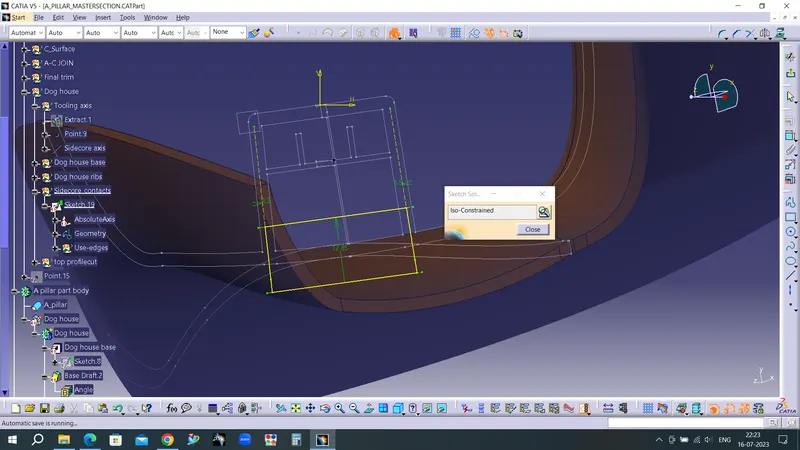
Side core contacts sketch
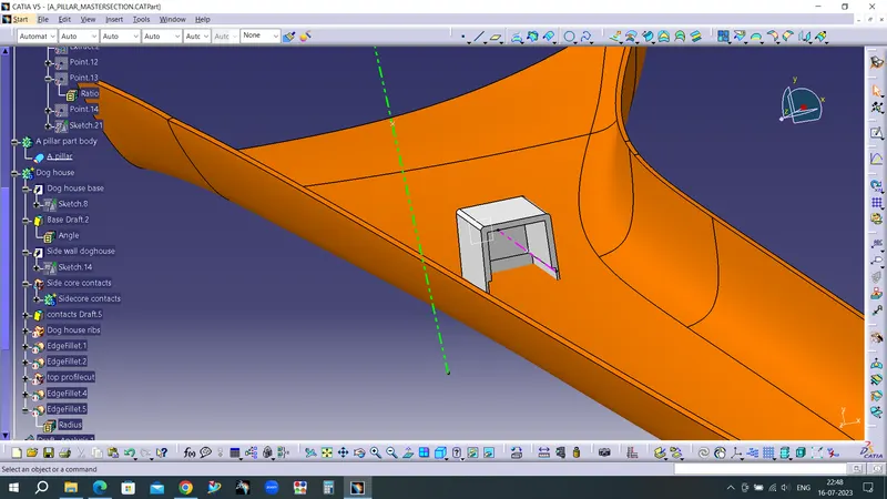
Part workbench of sidecore contacts
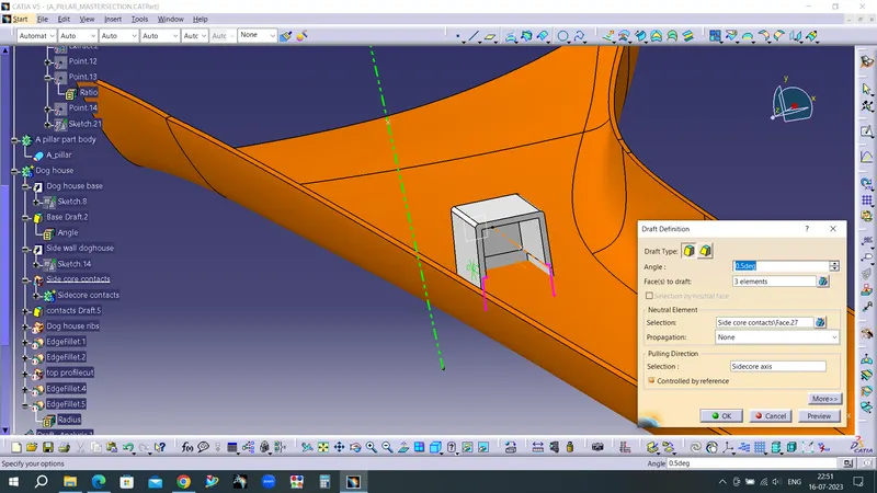
Appling drafts to sidecore contacts
Dog house top profile sketch
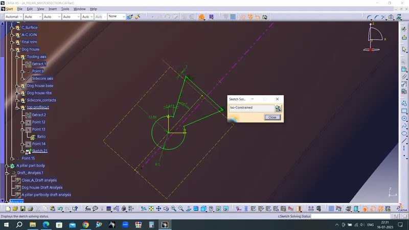
Part workbench of top profile
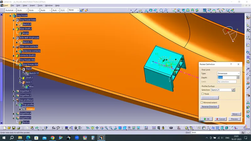
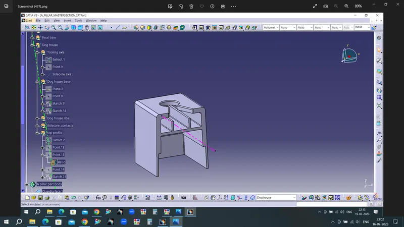
Final trim of doghouse with fillets
Draft analysis of Dog house
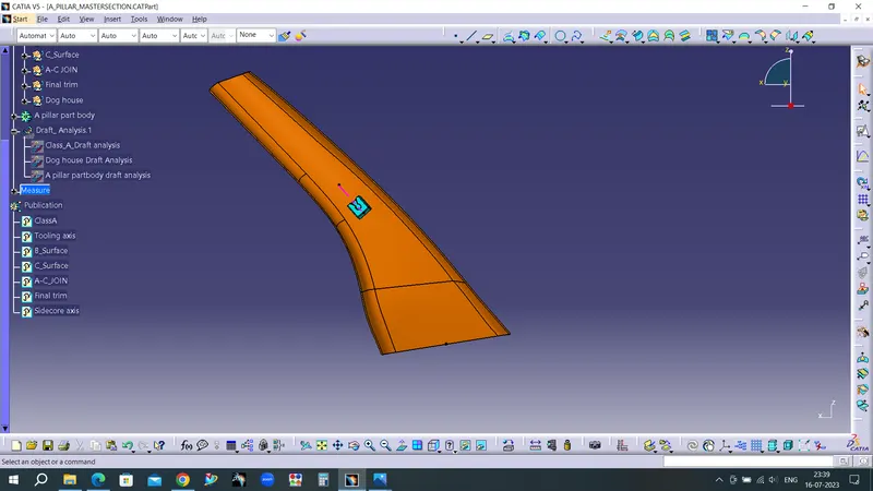
Adding dog house to A pillar part body
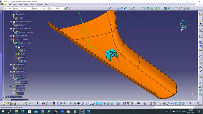
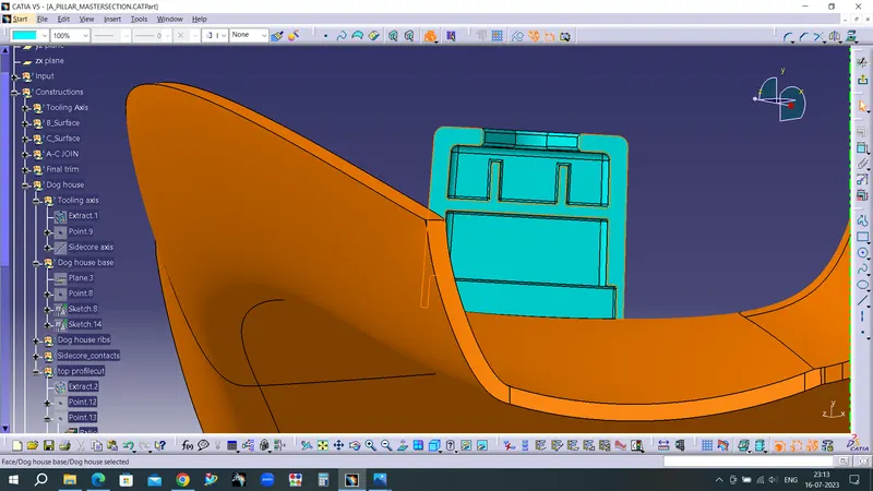
Final body
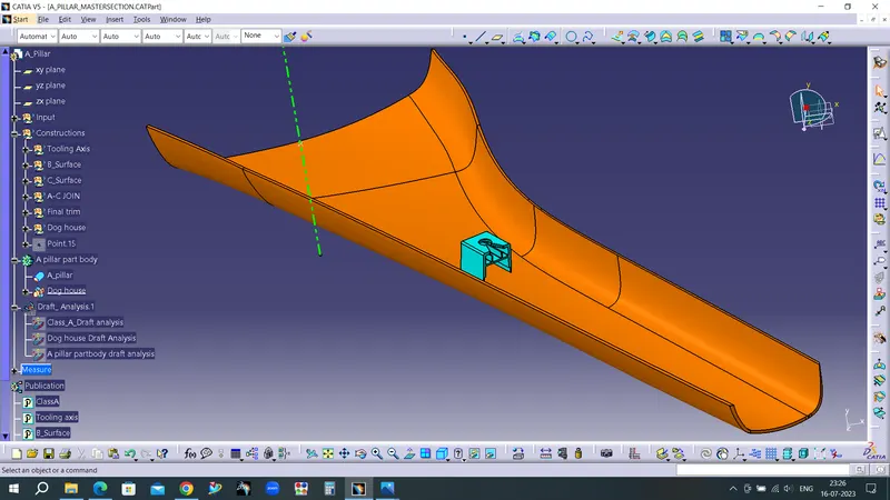
Tree structure
Front view
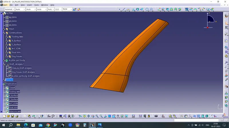
Side view