Week 11 - Project - A pillar Design with Master Section
AIM :
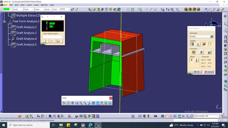
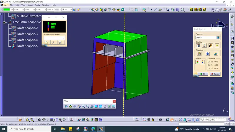
To create the A Pillar Design with the master section given as the intersection sketch with the Class A surface and create the tooling axis and perform the Draft analysis for the final solid part.
OVERVIEW :
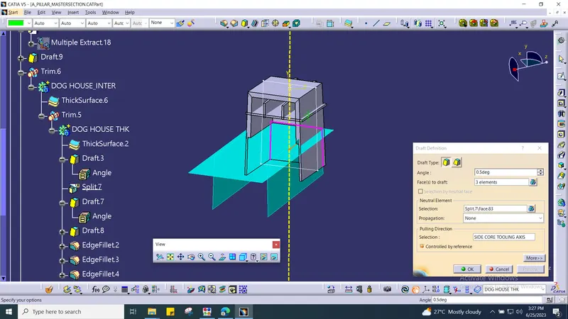
First create a geometrical set with proper sutitable name it as a Surface A. Then we need to do offset into 2.5mm and named it as a ( Surface b ). After that we will get some patch surface in fillet portion due to that fillet in "A" surface. Once we cleared all patches then join them together and name it as "B" surface improved. And then now do the sweep operating in A surface And then trim it and named it as C surface, then join together with A & C surface for final trim. Before going to do final trim make sure wheather the boundary having closed boundary or not then do the final trim with B surface & Joined surface A & C.Before doing close surface ensure that you have zero boundary surface After that do then closed surface. Then create a main tooling axis using two line bisecting method with point. And also create a side core axis using dog house rear surface.Then finally perform the draft analysis with the draft valve for 3 deg in closed surface and 0.5 deg for dog house side core.
MAIN TOOLING AXIS :
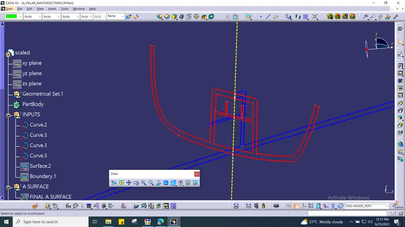
First to Create a tooling axis by given master section. Extract two parallel in master section with that we can Bisecting these lines to create a main tooling axis. By doing pre draft analysis in A surface with main tooling axis we can identify weather our tooling axis is correct ot not.
PRE DRAFT ANALYSIS :
Below image we can understand our tooling axis was correct and we are getting desire analysis output report.
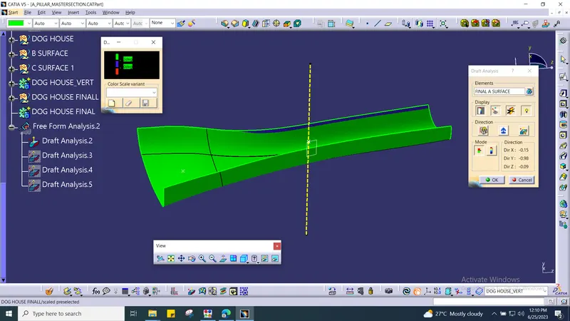
And small portion we are getting 0 degree draft so that it wont be a issue we can proceed further.
CLASS A SURFACE :
Below image given A surface. And we check any patches are there or not using boundary tool option. So Iam getting no pathches and clear boundary so I am proceeding further..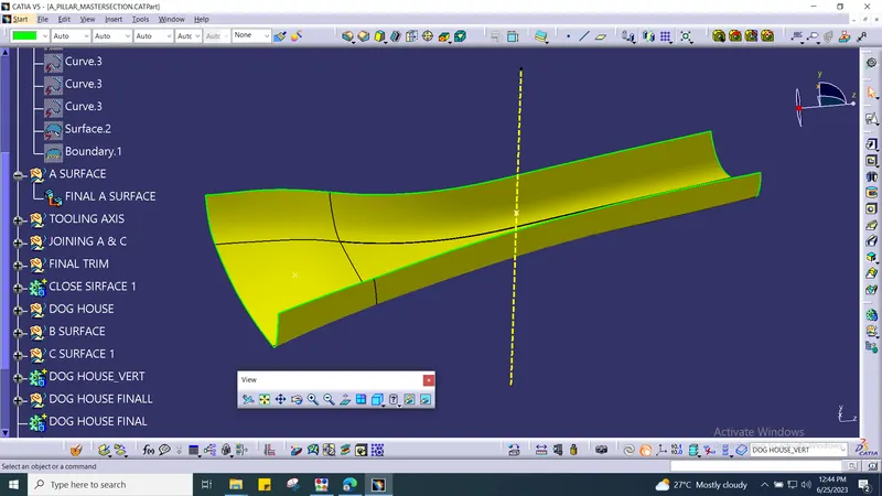
CLASS B SURFACE :
Offset the A surface 2.5mm and named it as a B surface. In B surface we can observe one patches. Inorder to fix this patches we need to sweep with references surface.
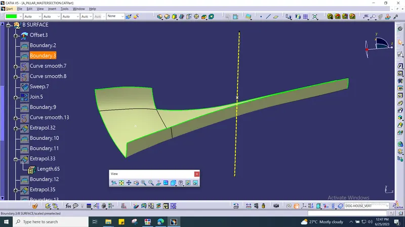
Below image after sweep operation then join it together and named it as improved B surface.
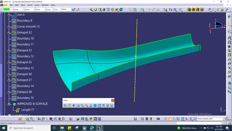
C SURFACE:
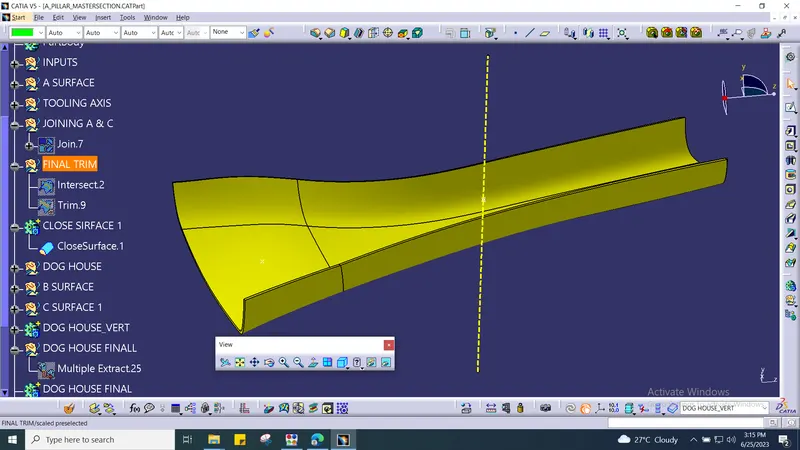
After creating A and B surface then we need to create C surface using A surface. First extract A surface then create a boundary in edges. Then these edges need to smooth curve then do the sweep. Finally join all the C surface.
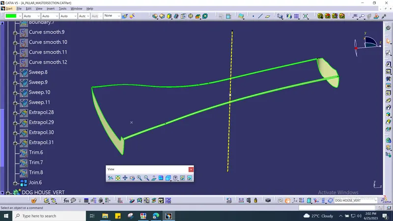
JOINING A & C SURFACE :
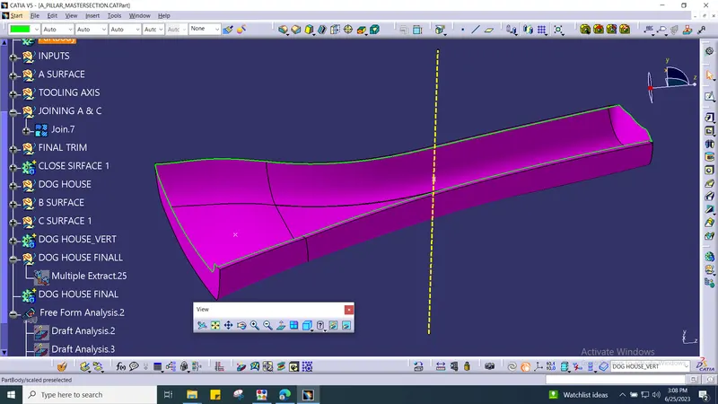
FINAL TRIM :
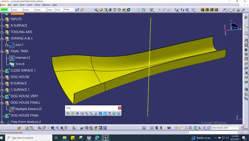
CLOSE SURFACE :
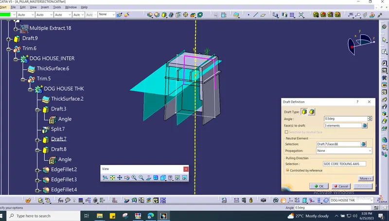
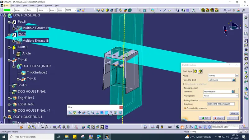
DOG HOUSE :
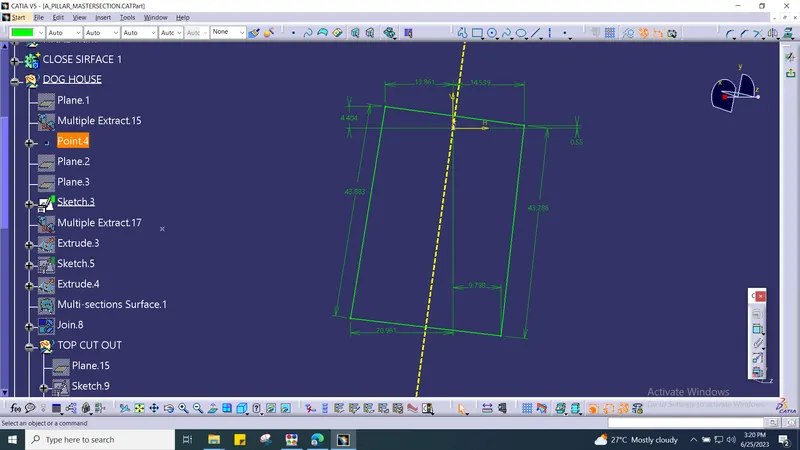
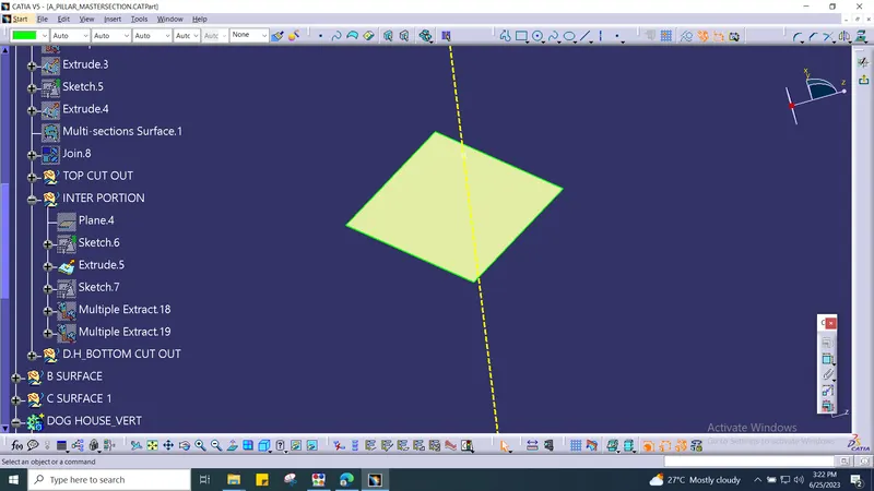
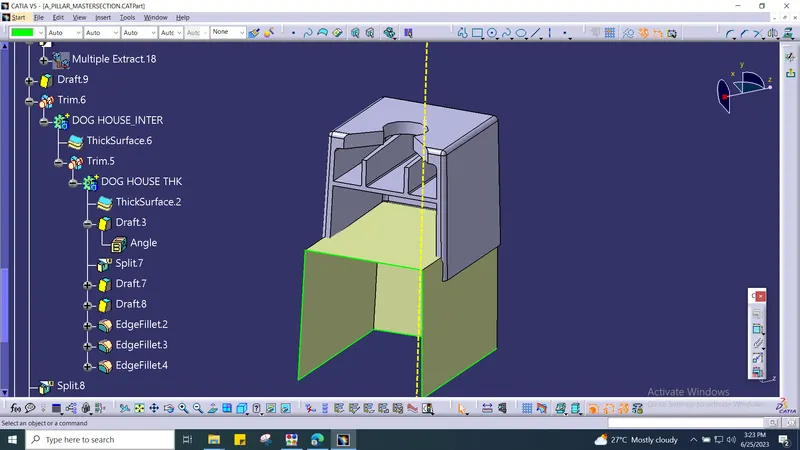
Dog house is an engineering feature used in plastic design. Dog houses are used as support feature. Sometimes other engineering features like snaps, locators, screw bosses are mounted on them to increase their strength.
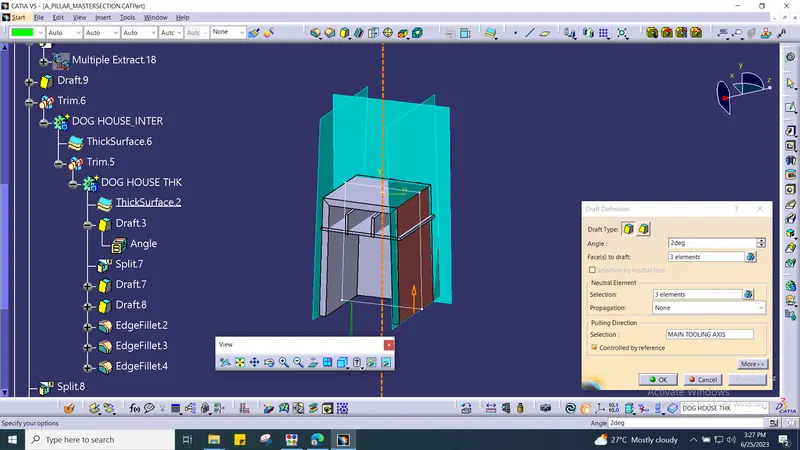
Dog houses are subjected to draft analysis to prevent breakage of the component during ejection from the mould cavity. Dog house and other engineering components are built on the B-surface
- Dog houses are designed to avoid SINK MARK created on the CLASS-A surface by screw bosses and to solve the length issues when giving screw bosses which need to be assembled to other components.
- It is also useful when perpendicular screw bosses are required on the part to the tooling direction.
- Make a rectangle to enclose the screw boss in it but make sure it is open from one side.
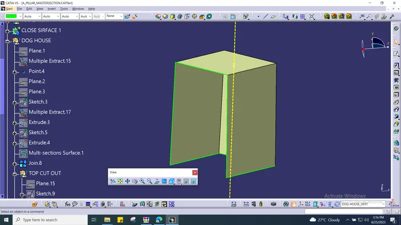
- Sweep it with tooling axis as the pulling direction inwards.
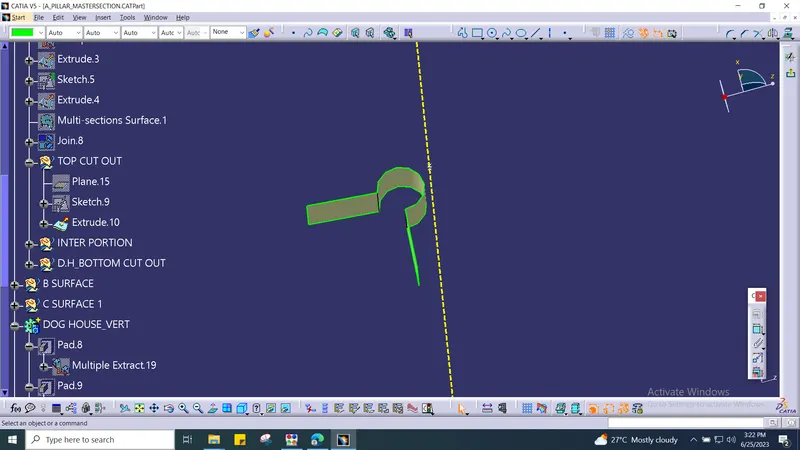
- Close the top face by using multi section surface.
- Thicken it by 2.5 mm to the outward direction.
FINAL DRAFT ANALYSIS :
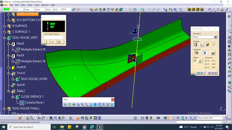
SIDE CORE DRAFT ANALYSIS:
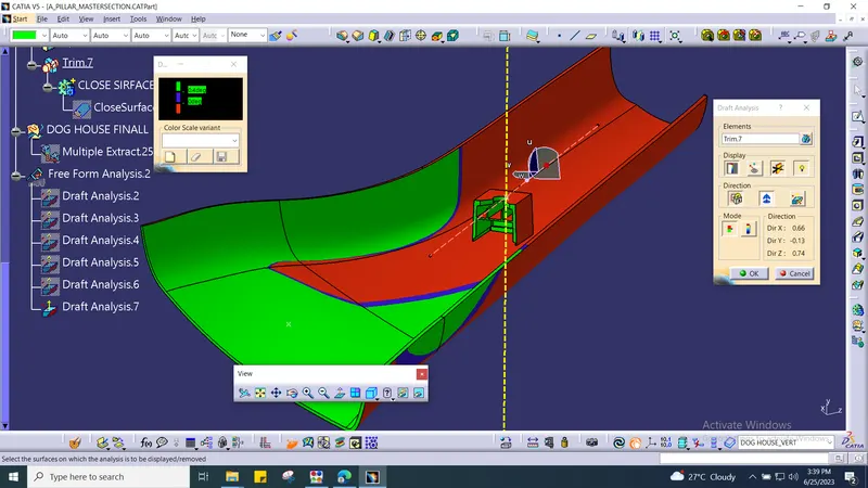
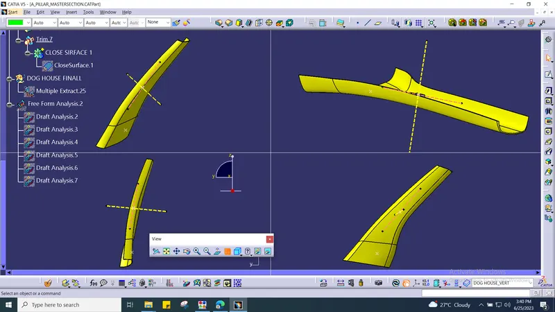
DIFFERENT VIEW :
CONCLUSION :
As per given instruction we have done the surface modelling, tooling axis, Side core tooling axis, Dog house & draft analysis.