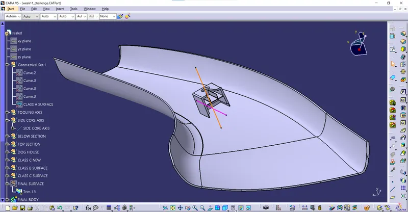
Week 11 - Project - A pillar Design with Master Section
AIM:
To create the A Pillar Design with the master section given as the intersection sketch with the Class A surface and create the tooling axis and perform the Draft analysis for the final solid part.
Class A
Visible surface is a Class-A surface. It provides the style team's look for the component, which the part design engineer uses to develop the component with all of the engineering requirements.
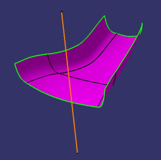
Tooling axis-Bisecting line Method
Tooling axis is the direction in which a core or cavity of mold opens. This Axis is very important to determine the orientation of the component in mold, core and cavity design as well as to run the draft analysis of the component.
To create the tooling axis i have created 2 main lines using bisecting method and then final tooling axis by bisecting the two lines generated.
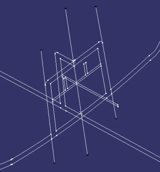
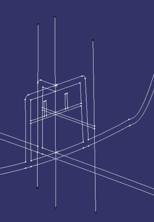
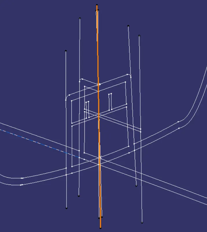
First figure shows creation of main line 1 which is formed by bisecting 2 lines present in its left and right.
Similarly second figure shows creation of main line 2 which is formed by bisecting 2 line present forward and behind.
Third Figure shows the creation of tooling axis (As shown in orange color) by bisecting main lines 1 and 2.
Draft Analysis of class A
Use the Featured Draft Analysis tool in the tools to now analyse the draft. After locating the compass and aligning it with the tooling axis, click on the lock symbol after aligning, and then click again on the surface after opening the draft analysis tool box.
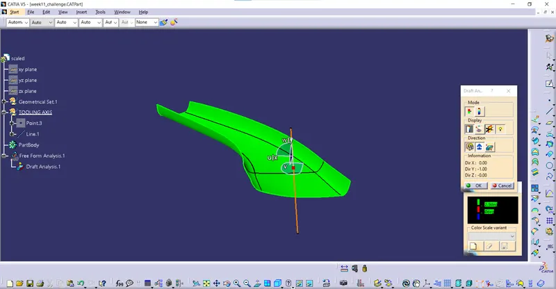
Creating Class B Surface:
First, offset the surface to 2.5mm, some errors may occur and some parts got removed. Click keep all sub-elements. And use fill, sweep, boundary, extrapolate, and trim commands to close the patches. Then join all together
Creating Class C Surface:
At first extract the boundaries of the Class A surface and B surface, and use the sweep option to create the c surface
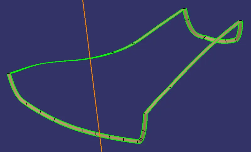
Final output
Now trim the Class A , Class B and Class C surfaces to get the desired output. And make it as a solid body using close surface feature in part workbench.
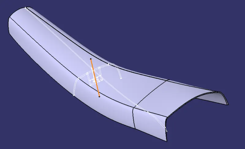
Draft Analysys on Solid Body
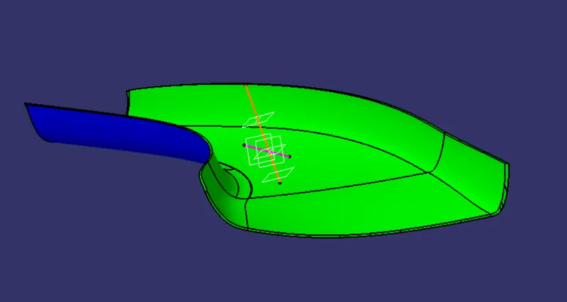
DOG HOUSE
A plastic design element called a "dog house" is employed. Dog house are a supporting element. In order to strengthen their robustness, snaps, locators, and screw bosses may occasionally be put on them.
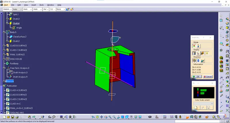
Draft analysis is applied to dog house to minimise component breakage during ejection from the mould chamber. On the B-surface, a dog house and other engineering elements are constructed.
DOG HOUSE Creation
Dog houses are made to prevent the SINK MARK that screw bosses leave on CLASS-A surfaces and to address the length problems that arise when attaching screw bosses to other components.
It is especially helpful when the part needs screw bosses that are perpendicular to the direction of tooling.
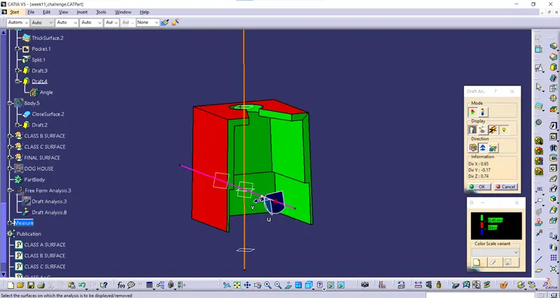
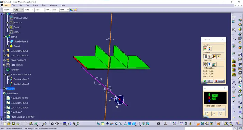
Below figure show draft analysys on dog house with respect to main tooling axis and side core axis and draft analysys of ric using side core axis.
Draft analysys using main tooling axis
Draft analysys using side core axis
Draft Analysys of Dog House Rib using side core axis
Final Draft analysis
Use the Featured Draft Analysis tool in the tools to now analyse the draft. After locating the compass and aligning it with the tooling axis, click on the lock symbol after aligning, and then click again on the surface after opening the draft analysis tool box.
Do this for both the axis and analyze A B C surfaces and Dog House.
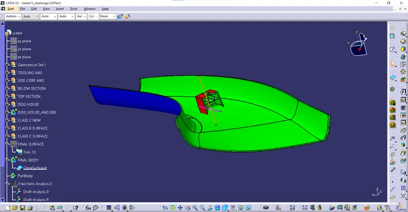
Final Solid Body