Week 11 - Project - A pillar Design with Master Section
AIM:
To create the A Pillar Design with the Master Section given as the intersection sketch with the Class A Surface and create the Tooling Axis and perform the Draft Analysis for the final solid part.
CLASS A SURFACE:
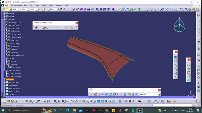
- A Surface is which the part design engineer uses to develop the component with all of the engineering requirements.
- Check for continuity of the given surface using Join or Boundary commands.
TOOLING AXIS:
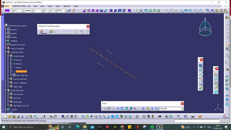
- Tooling Axis is the direction in which a core or cavity of mold opens. This axis is very important to determine the orientation of the component in mold, core and cavity design as well as to run the Draft Analysis of the component.
- In this case, we use bisecting method to find the Tooling Axis.
- Two lines from the Master Section was taken as reference and a center point is created between the two lines.
- The Tooling Axis is then created by Bisecting the two reference lines.
SIDE CORE AXIS:
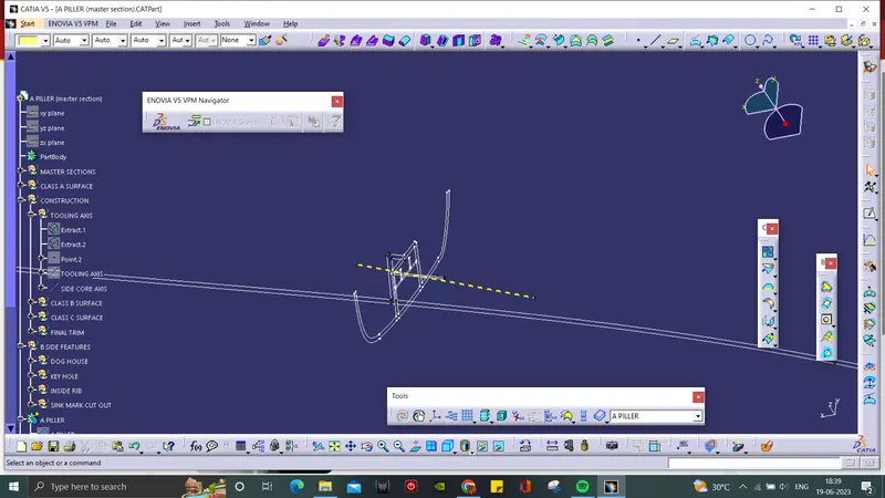
- Same procedure is followed for Side Core Axis which is the axis for the Dog House.
- And the axis is created from the center point extracted from Master Section.
CLASS B SURFACE:
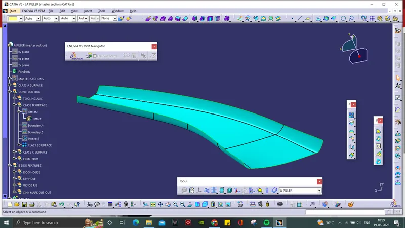
- Since the component thickness is 2.5mm, the A surface is Offsetted by 2.5mm.
- Some discontinuities will happen which is then repaired by using Muti-section, Fill and Trim commands.
- In this case, Sweep command is used and then Joined together to form Class B Surface.
CLASS C SURFACE:
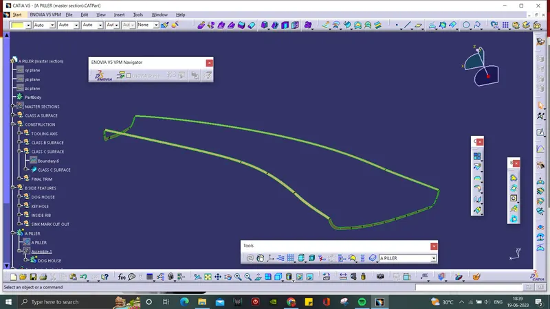
- A boundary was created along A surface.
- The boundary as guide curve Sweep is used to form Class C Surface with A surface as reference surface.
FINAL TRIM:
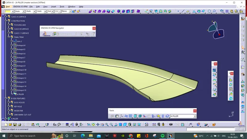
- At the final trim part, the A surface and C surface are joined together.
- B surface is Extraplated and then Trimmed with A and C surface to form the A-Piller surface.
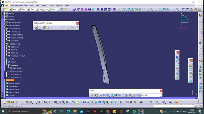
- Then at part design, the hollow part is converted into a solid A-Piller by using closed surface command.
DOG HOUSE DESIGN:
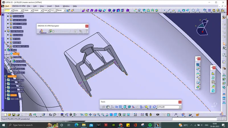
- Dog House are B side feature that used to support other B side features.
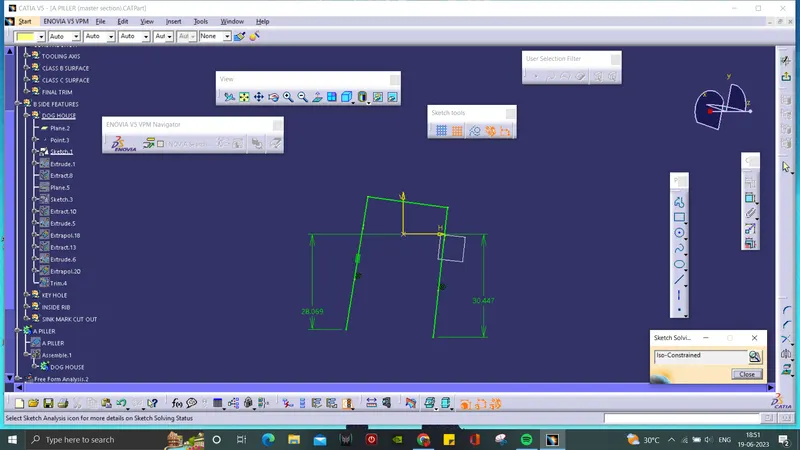
- The sketch is drawn by reference of the Master Section.
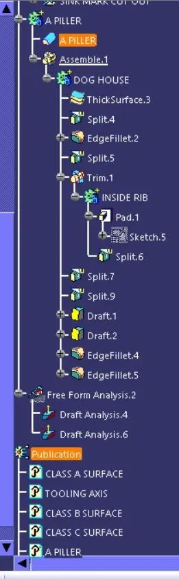
- The Dog House surface is created by using Trim and Split commands.
- Then thicksurface is used to make it solid.
- It is then drafted and filletted through the axis created for doghouse.
- Finally, the Dog House is assembled with the A-Piller.
KEY HOLE ON DOG HOUSE:
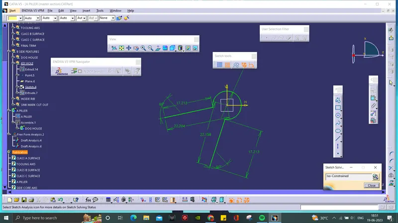
- A Key Hole sketch is drawn on the top of the Dog House.
- The sketch is then Extruded and Split to form Key Hole on the Dog House.
RIB INSIDE DOG HOUSE:
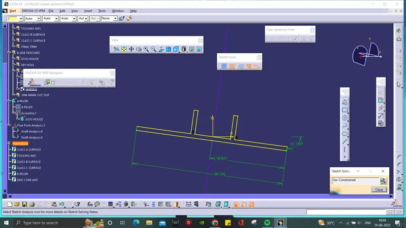
- According to the Master Section, a rib like structure should be created inside the Dog House.
- The sketch is taken from the reference of Master Section and then it is Padded to make it solid.
- Then the solid part is Trimmed with the Dog House.
DRAFT ANALYSIS:
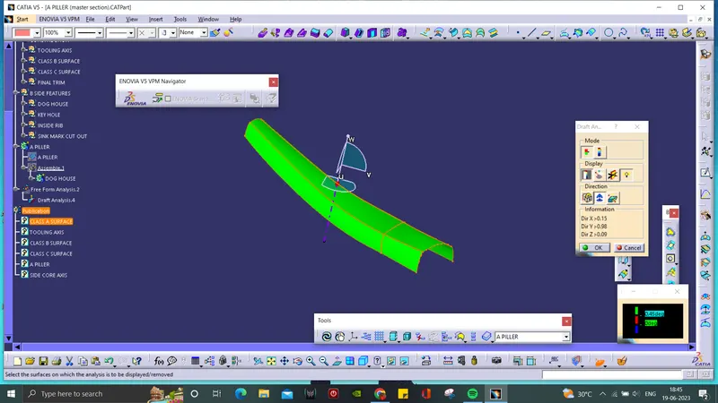
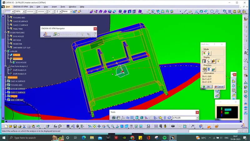
- In Draft Analysis tool bar, use the compass and drag it to set along the Tooling Axis of the surface.
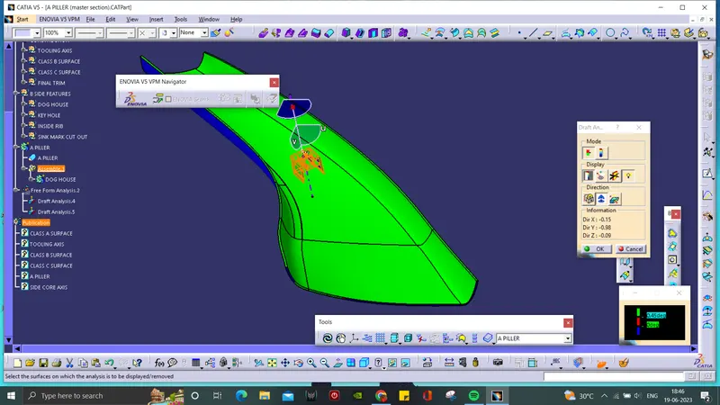
- By clicking the surface, it will turn into green colour. if it is blue, the analysis was inversely done which is corrected just by flipping the direction.
- Draft Analysis on the solid part is in green and red regions.
- Individual Draft Analysis is done for both solid and surface.
DOG HOUSE DRAFT ANALYSIS:
- Dog House Draft Analysis is done through the Side Core Axis.
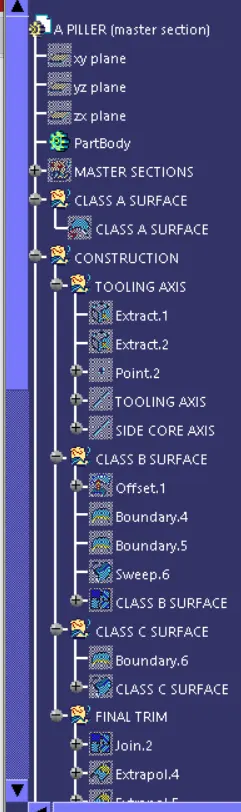
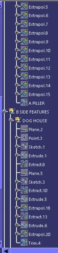
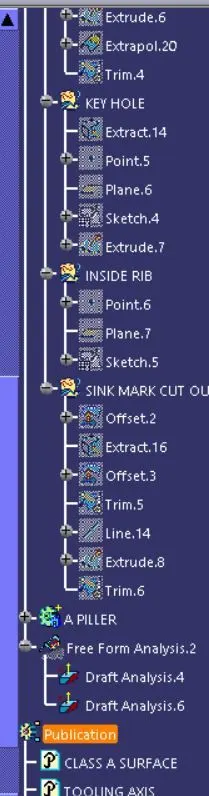
TREE STRUCTURE:
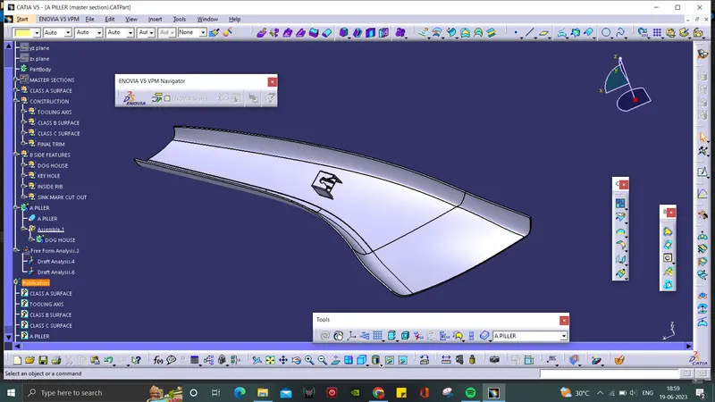
ISOMETRIC VIEW:
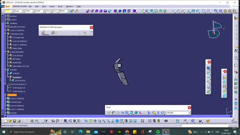
FRONT VIEW:
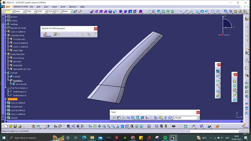
TOP VIEW:
SIDE VIEW:
CONCLUSION:
The B surface, C surface, Solid part and Dog House for the A-Pillar is created and the Draft Analysis are done.