Week 11 - Project - A pillar Design with Master Section
AIM: To create A PILLAR plastic design with Master Section.
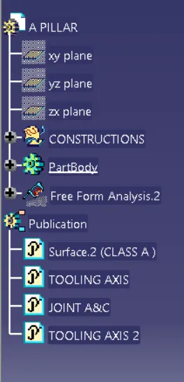
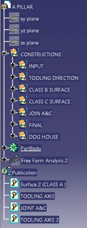
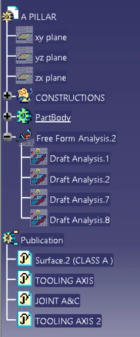
Objective: In this project we are going to design A PILLAR with master section considering all the design rules using different tool in CATIA V5 software. The approach includes creation of Class B surface keeping 2.5 mm thickness in mind for the complete component. The design also included Class C creation from the given parent surface. Ensure proper tree structure and all the sketch should be ISO constrained.
- To chack continuity of class A surface
- Create the Toolling Axis
- To perform draft analysis of the plastic component.
- Creation of Class B and Class C surface using input Class A surface
- Make a Close Body
- Creating a solid part from Close Body
- To create Dog House considering the design guidelines.
- To perform the Draft analysis on the final plastic component.
Constraints:
- No change in Class A are allowed.
- Part thickness can't deviate by more than +- 30%
- All design rules should be strictly followed.
- All surfaces should be closed before converting to solid
- All faces should meet the allowed draft requirements.
INTRODUCTION:
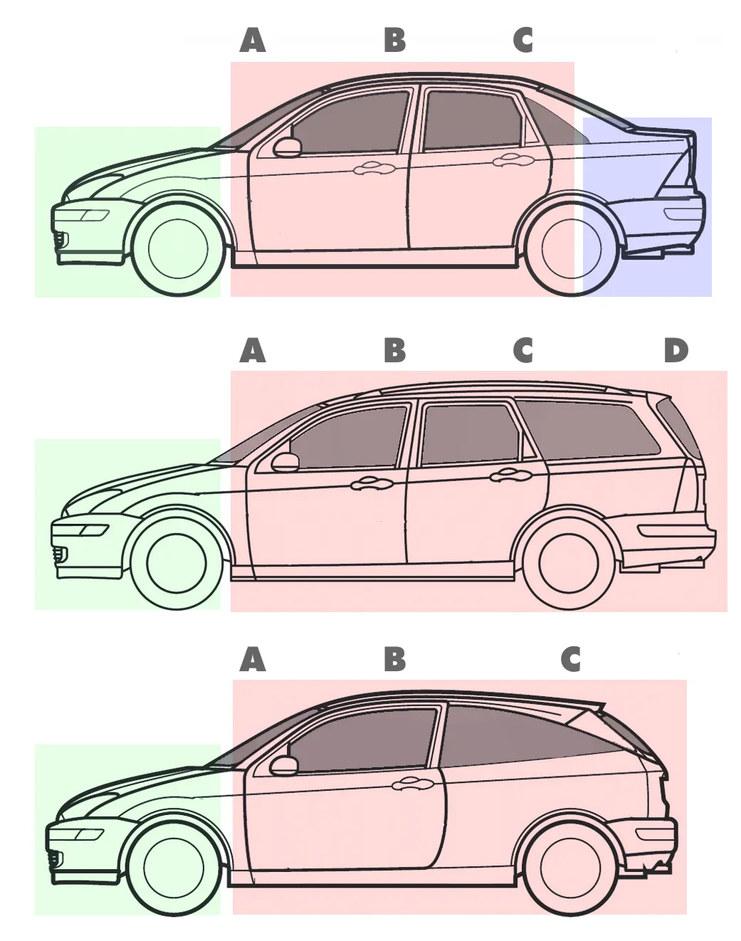
The number of pillars will vary according to the type of car. Most sedans and hatchbacks will have three (A, B & C) pillars whereas larger cars like SUVs will have all the four (A, B, C & D) pillars. Hardtop structures (often referred to as pillarless hardtops) will have only two (A & C) pillars.
PILLARS are lettered front to back. A-Pillars straddle the windshield, B-Pillars are in the middle of the passenger compartment (just behind the front doors) and C-Pillars are those at the rear of the passenger compartment.
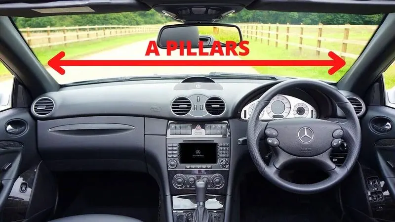
A-PILLAR:
-
A-pillars are located on either side of your car’s front window or windshield.
- They also hold the hinges of your front doors.
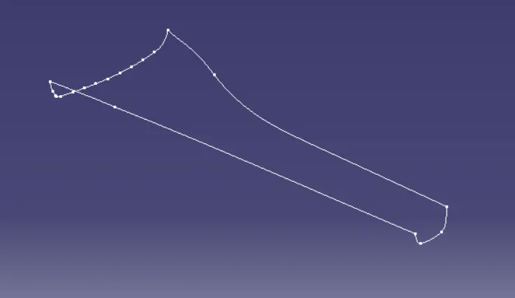
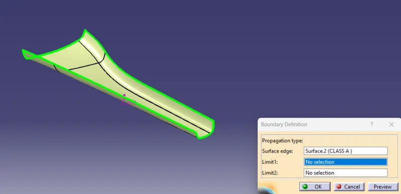
INPUT CLASS A SURFACE:
Checking the continuity of the A surface. As we can see there is no black dots that means there are no gaps in boundry of class A surface.
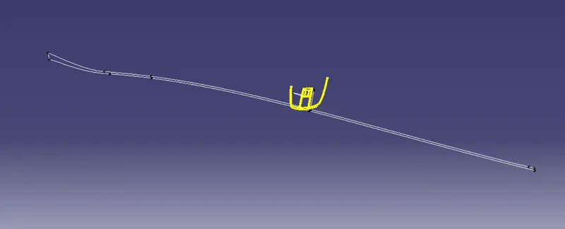
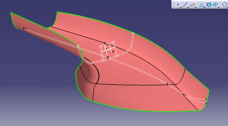
MASTER SECTION
TOOLING AXIS:
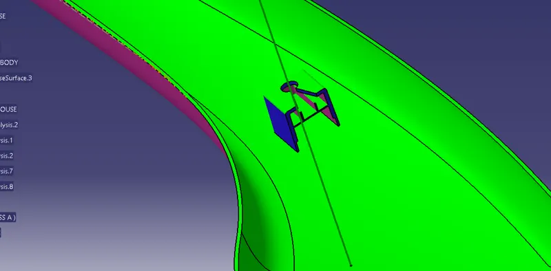
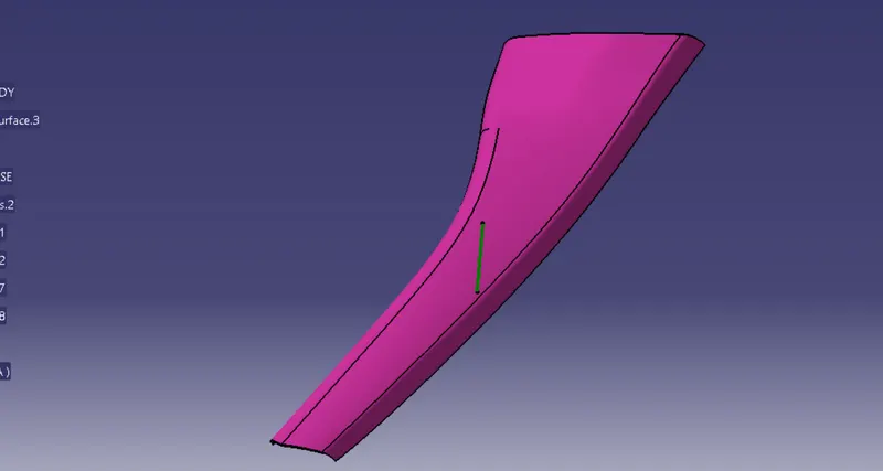
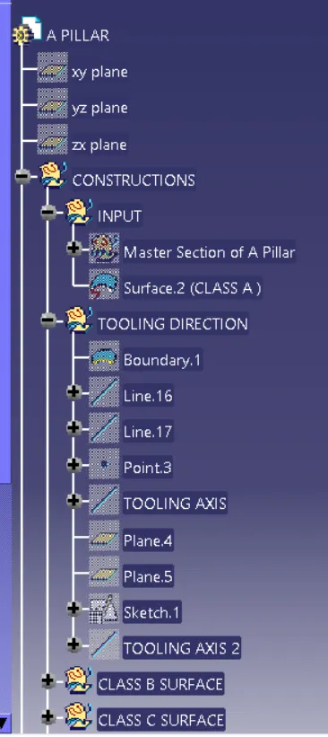
First we have to observe and study the class A surface to create the "Tooling Axis" for the component, and for the above given A PILLAR. Here i use a master section to create a tooling axisby the use of doghouse boundry line. Initially, I draw a line along with doghouse master section side line and then create point between two lines.After that i draw a besecting line through using two lines and a point. Once the bisecting line get, rest of the line make construction line. Now analyse tooling axis by analysing draft and class A surface making an angle direction inbetween 0-3 degree by draft analysis.
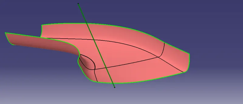
DRAFT ANALYSIS:
To perform draft analysis, click on Insert>Analysis>Feature Draft Analysis
Once the draft analysis toolbar is opened, go to the display block and select the 'Analysis under the running point' command to check the angle for different sides (walls and inclined plane angles) on the class A surface. The color scale on the bottom visualizes, whether the draft angle meets the requirements or not (3 deg) by indicating the colors Green, Blue and Red. Once the draft angle analysis was done, we need to align and fix the compass to the tooling axis of the class A surface.
To align and fix the compass to the tooling axis, go to the direction block in the draft analysis toolbar and click on the 'Use the compass to define the new current draft direction option (or just click on the compass symbol). Now bring the compass to the surface and align it to the tooling axis of the class A surface and click on the lock symbol beside the compass in the direction block. Once we click on 'ok' on the draft analysis toolbar, we can finish the draft analysis process.
NOTE: First check shading is in material mode (Go to the customise view parameter)
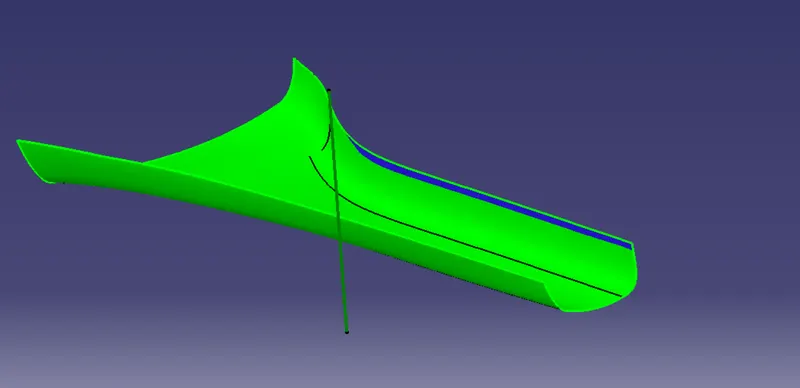
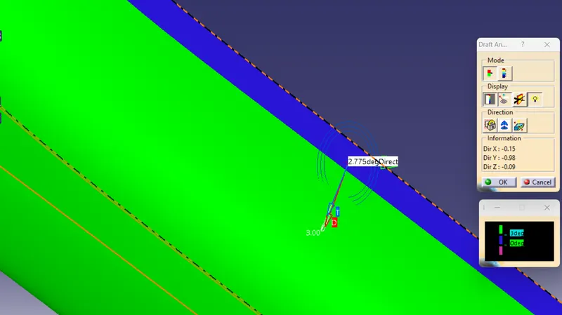
We can clearly see in the above figure draft angle is set to be 3 degree and all the surfaces are in green and blue color ( Blue color draft angle shows 2.775 degree). 2.7 degree draft considerable in blue color. Also we can see that there is no red color shows it means we can consider tooling axis is now main tooling axis.
CLASS B SURFACE:
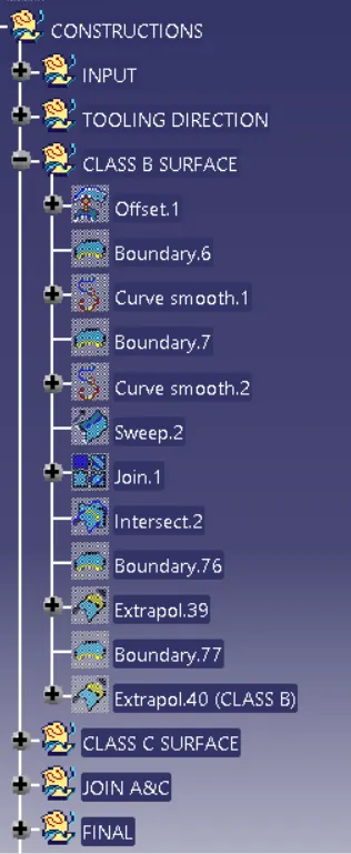
To create the class-B surfeace, I will go through the direct offset method becouse here the given A PILLAR surface are very difficult to find out where to start class-B surface so to do that we have to directly offset it upto desired thickness (2.5mm) and then we will go through, like some part are missing in offset surface. So that surface we have to fill by using extraction, untrimmed, extrapolation, trimming, joinning, sweep tool in surface design workbench etc.
Here it showing warning that some element or patches are missing so we have to click "OK".
Offset value = 2.5mm
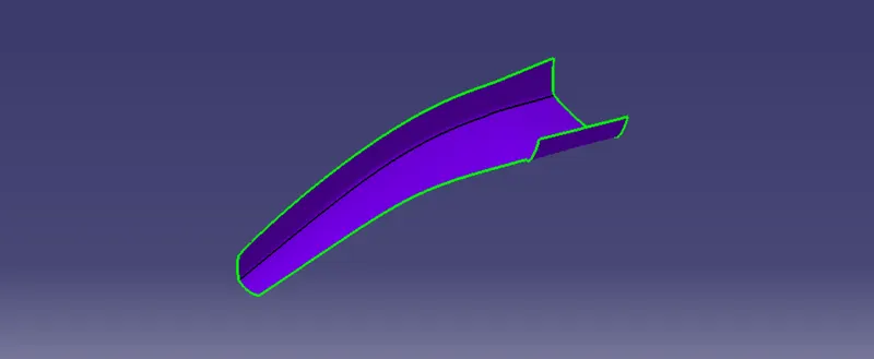
For missing patch we create a boundry along with edge of offset surface and then sweep it with reference surface.
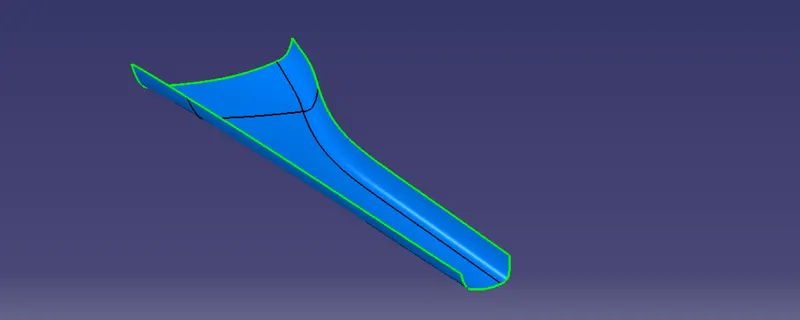
CLASS C SURFACE
It is the combination of Class A, Class B and Class C surfaces. To create a class C surface, I used the sweep command by considering the outer boundary of the class A surface. In the sweep command, go to the 'line' command in the 'profile' block and the subtype is 'with reference surface'. Now select the outer boundary and reference surface, give 90 deg in the angle and select the direction to sweep, in this condition the class B surface is under the class A surface so select the inside arrow to sweep. Now I joined all the sweeped surfaces by using the 'join' command and then I trimmed the Class A, Class B and Class C surfaces to make a closed surface, to make a Solid body.
Boundary creation and Sweep command:
Here we use one by one sweep and boundry command becouse there is sharp edge in the class A.
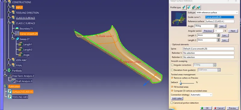
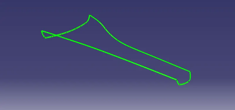
Join class C with class A surface also check boundry of joined surface ensure that no gap in class A & C joined surface.
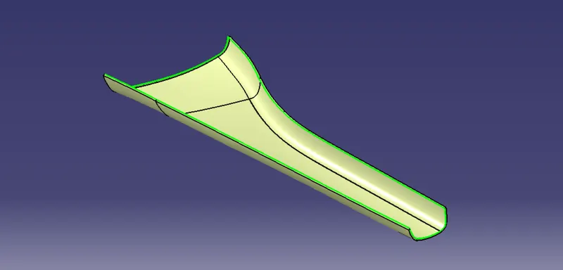
Check the intersection of class B surface with joined class A&C surface insecting or not. If not, then extrapolate where isn't inntersecting and then again check intersection by the use of intersection tool in shape design workbench.
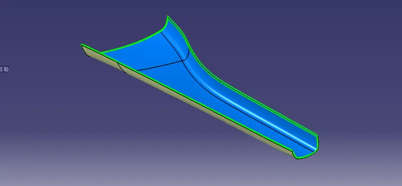
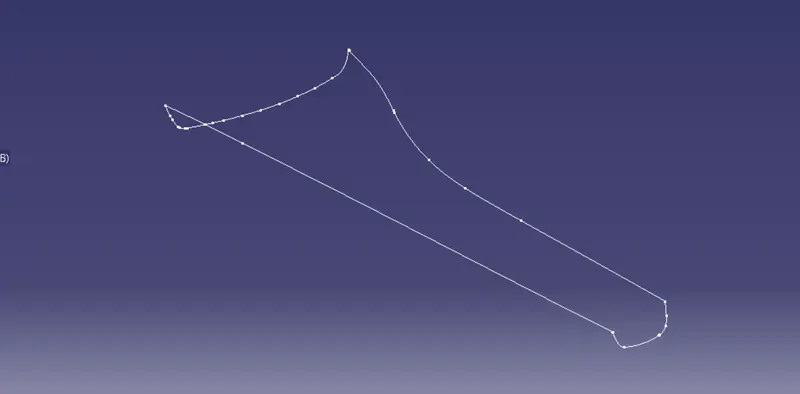
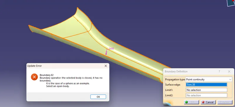
FINAL TRIM Class B with Joined Class A & C
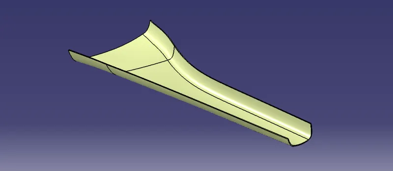
Now we have to check boundry of final trim, below we clearly see that getting error it means final trim is fully connected
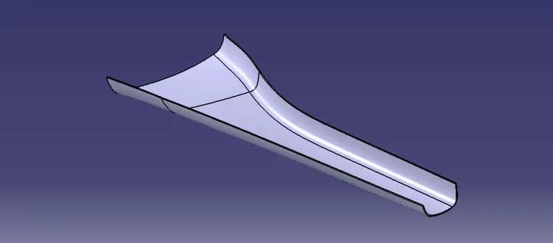
The Close surface is now converted into solid part using close body command in part workbench.
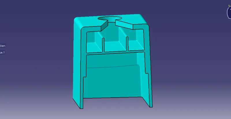
DOG HOUSE CREATION THROUGH MASTER SECTION:
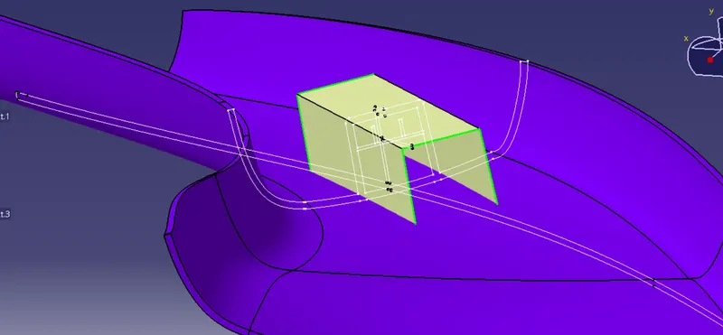
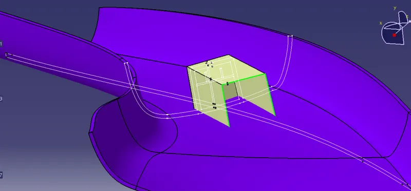
By studing the master section it looks like doghouse on A-PILLAR.
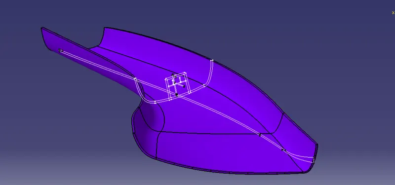
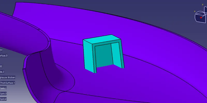
- By following the Design guidelines Dog house is created.
- Sketch is made by using the Master Section provided.
- Then it is converted into a Close body.Draft is provided according to guidelines max 0.5 degree.
- Fillet is provided to the edges according to the Master Section and minimum fillets.
Surface thicken
DogHouse CORING
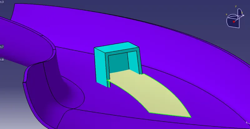
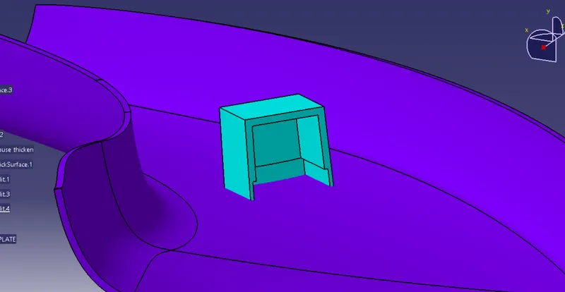
Now Creating BASE PLATE, RIB 1 and RIB 2 on DogHouse
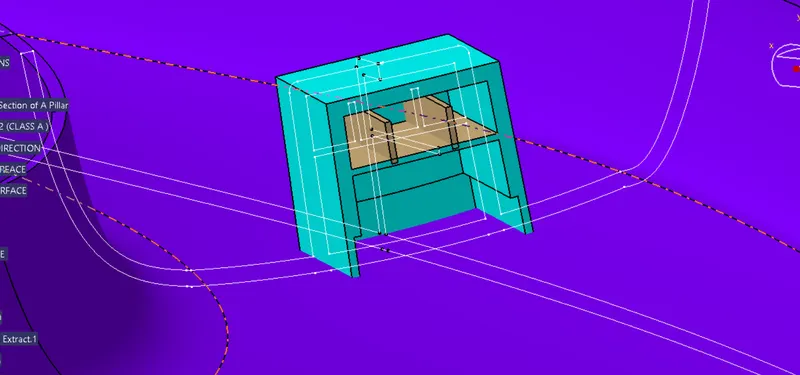
DogHouse TOP SECTIONING
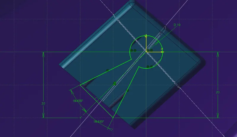
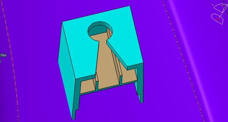
Drafting and giving edge fillet
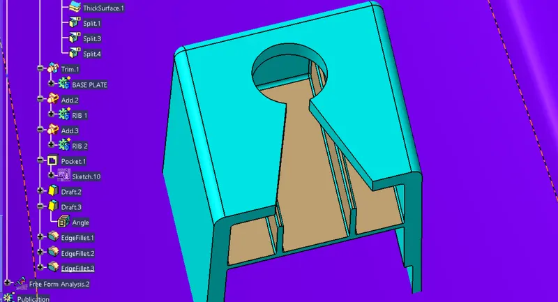
DOG HOUSE
Trim with clsoe body of class A
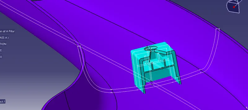
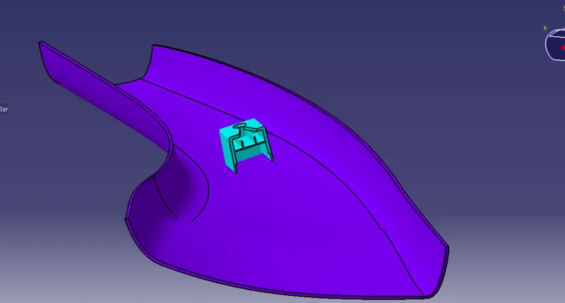
DRAFT ANALYSIS OF FINAL BODY
DOG HOUSE ANALYSIS ( Draft angle vary so i took 0.2deg becouse drafted body is cut at 0.2degree along with pulling direction and base plane)
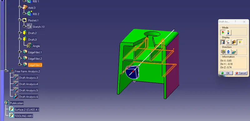
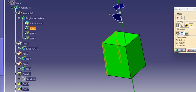
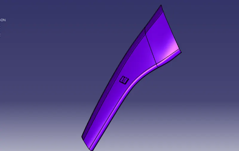
Whole BODY DRAFTING ANALYSIS ( Draft angle is 3 deg)
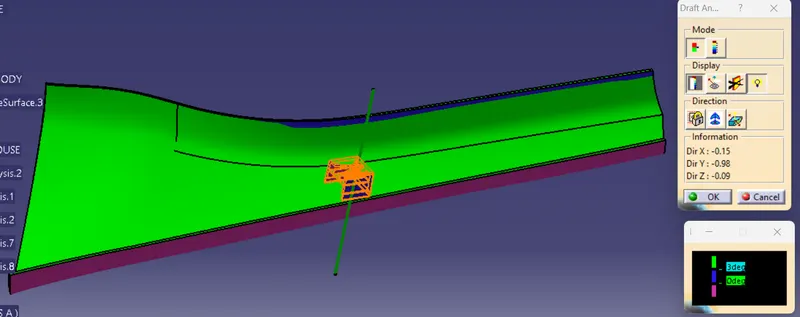
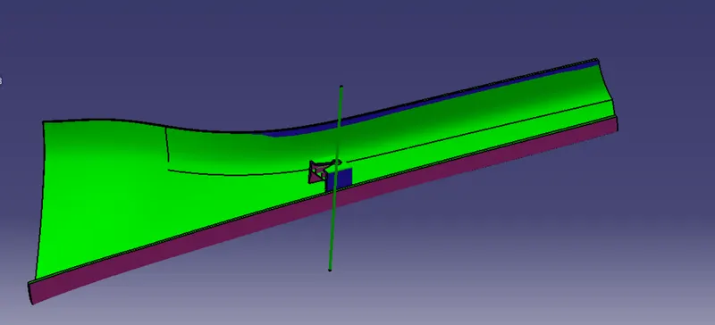
Back view of analysis
ISOMETRIC VIEW
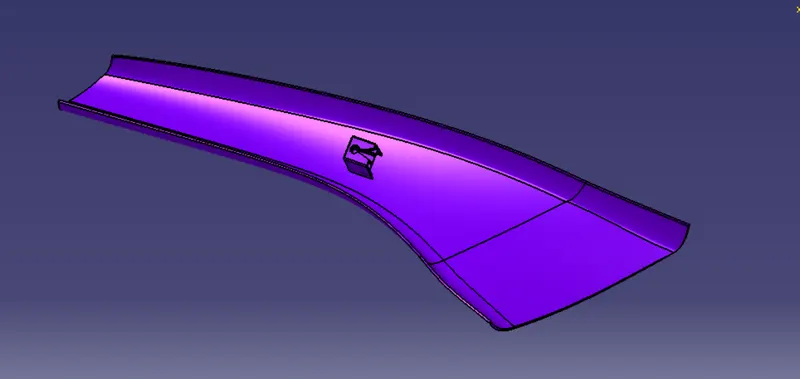
RIGHT SIDE VIEW
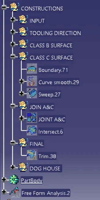
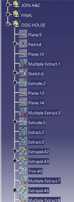
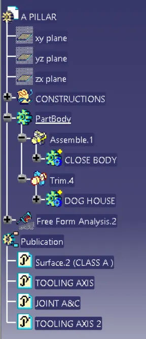
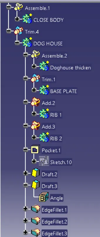
TREE STRUCTURE:
CONCLUSION:
Here we studied A PILLAR with Master Section where we use different tools in surface design and part design workbench in CATIA V5 software. In this project first we create solid body of given input class A surface with master section and attach enginnering feature like DogHouse on solid body by the use of master section, also analyse the draft.