Week 11 - Project - A pillar Design with Master Section
A pillar Design with Master Section
AIM:
To create the A Pillar Design with the master section given as the intersection sketch with the Class A surface and create the tooling axis and perform the Draft analysis for the final solid part.
INPUT MASTER SECTION AND CLASS A SURFACE:
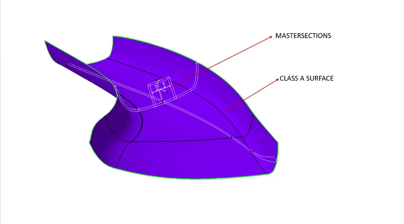
STEP 1- TOOLING AXIS CREATION:
- Its is the axial direction in which mold opens and closes during the operation.
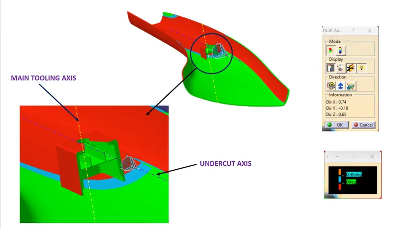
- Here in this case we required two tooling axes one for the whole component and second for dog house.
- It is the first and very important step in the product design procedure.
- using bisecting method and input mastersections it is going to be created as shown in fig.
- And similarly undercut axis is also created by using mastersections and plane.
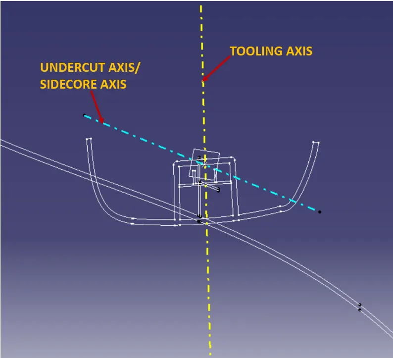
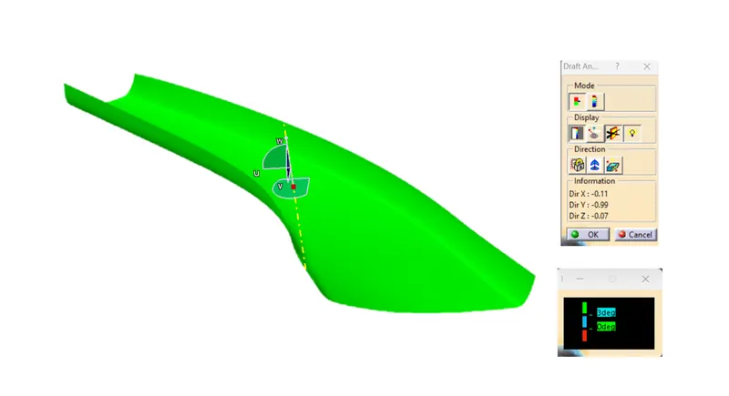
STEP 2- CHECKING WHETHER THE PROVIDED DRAFT FOR GIVEN CLASS A IS CORRECT OR NOT:
- For that select the tool option insert a analysis> feature draft analysis
- Don't forgot to change material mode before selecting the tool.
- Now, drag the campass and aligned it with the tooling axis correctly then lock it.
- Then give a nominal draft value of 3 degree and calibrate the provided draft match or not .
- Here u can also check the draft of respective surface using option draft under running point available in display section which helps you to analyse it better. If it seems correct, you can proceed further to steps-3.
STEP 3- CREATION OF CLASS B SURFACE:
- Offset the class A surface to required thickness of 2.5 mm which is the thickness of component.
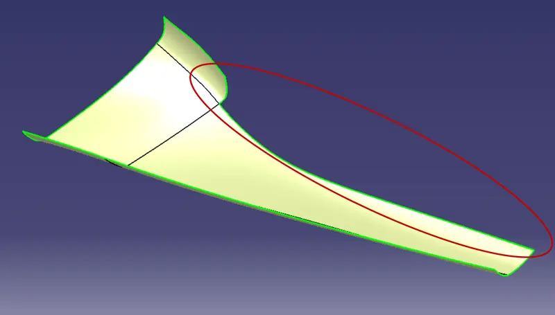
- It seems like not complete object offseted properly one big patch is missing here so try to use mastersections to correct it make join it using join cammand and make final b surface as followwing one.
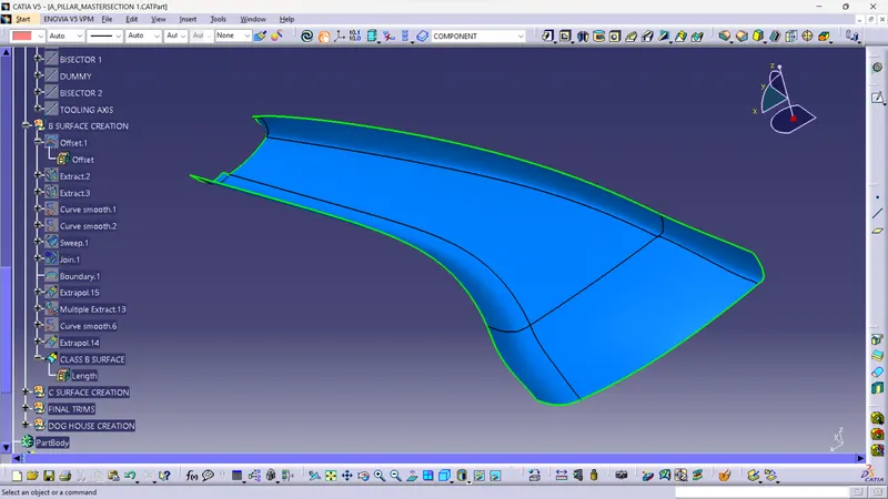
STEP 4- CLASS C SURFACE CREATION:
- Extract the surface and respective boundries of them.
- Using sweep cammand and its sub-types make single and closed profile of c surfaces.
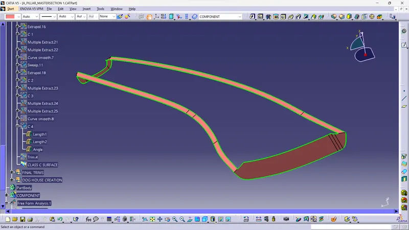
STEP 5- TRIMMING AND JOINING:
- Finally join the class c and alass A surface together
- And now trim the joined surface with respect to class B surface then we get our final 3D surface.
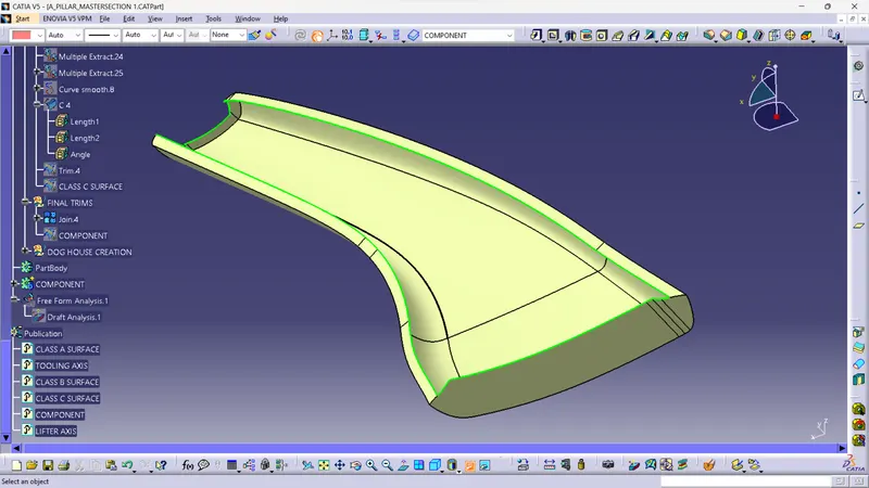
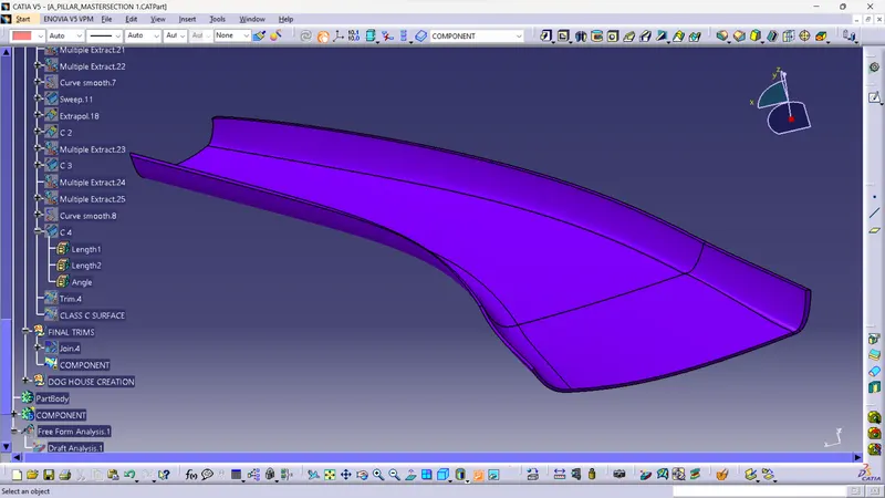
STEP 6- CREATING A SOLID OBJECT
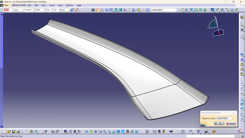
- Insert a body and convert the 3D surface to a solid component using close solid option.
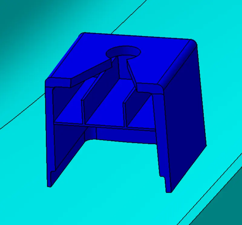
STEP 7- CREATION OF ATTACHMENT FEATURE DOG HOUSE:
- Now, use a mastersectons as a referance and create a sketch for dog house.
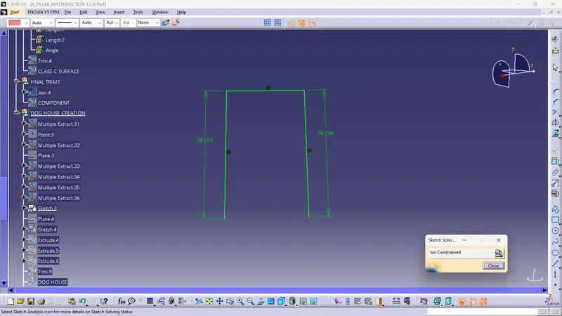
- similarly create a sketch for another side of dog house and in which use it as output feature.
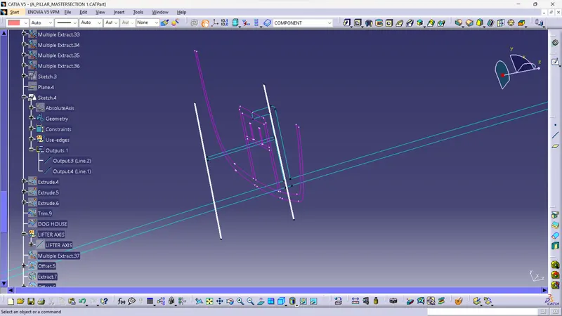
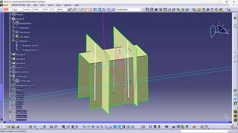
- then extrude them all and finally trim them with respect to each other to get 3D version of dog house.
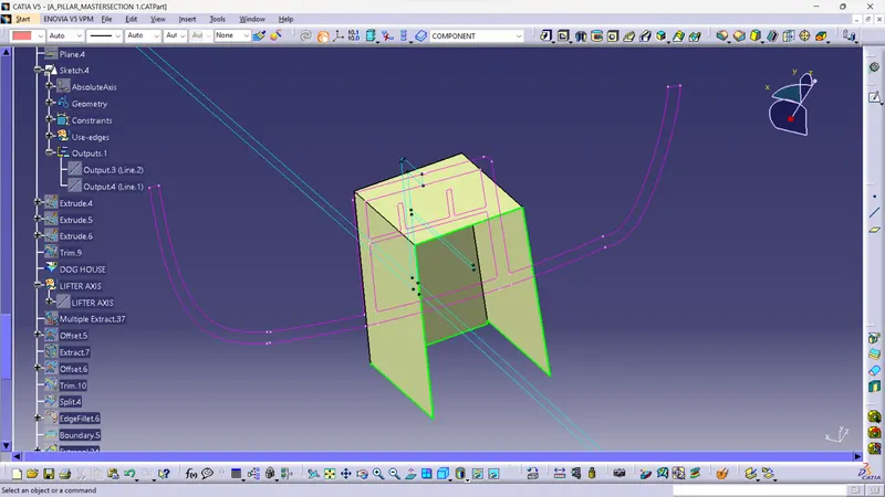
- similarly insert a body for dog house and transform it to a solid feature using Thicken option.
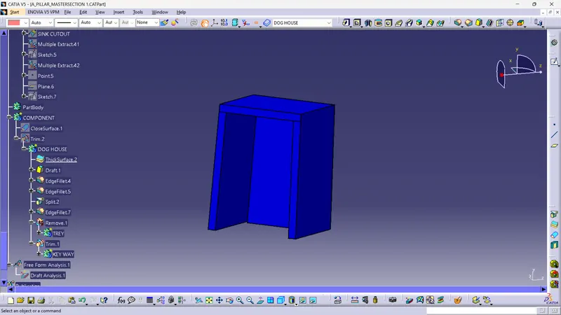
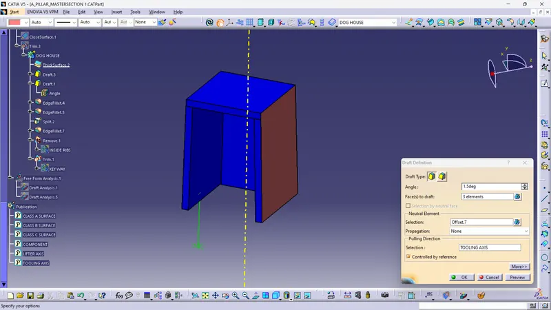
- Draft provided for mastersections was very minimum provide proper required draft of 1.5 mm for the outer surface wall of dog house.
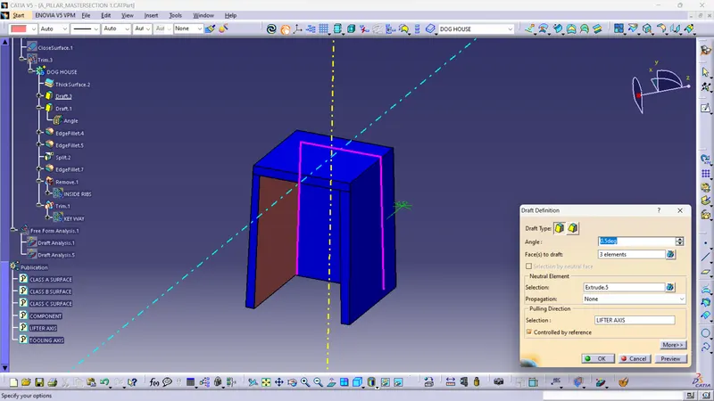
- similarly provide internal draft for 0.5 mm with referance to lifter axis of dog house.
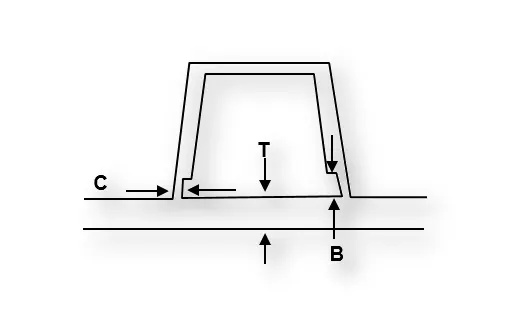
- To avoid sink mark defect on the final component providing an undercut below dog house with considering al its design rule
-
Doghouse wall thickness at the intersection of the part wall ( C ) should be 40% or less than the main wall stock ( T ).
-
The height of ( B ) should be between 3.0 – 6.0 mm
- then split it from the dog house body.
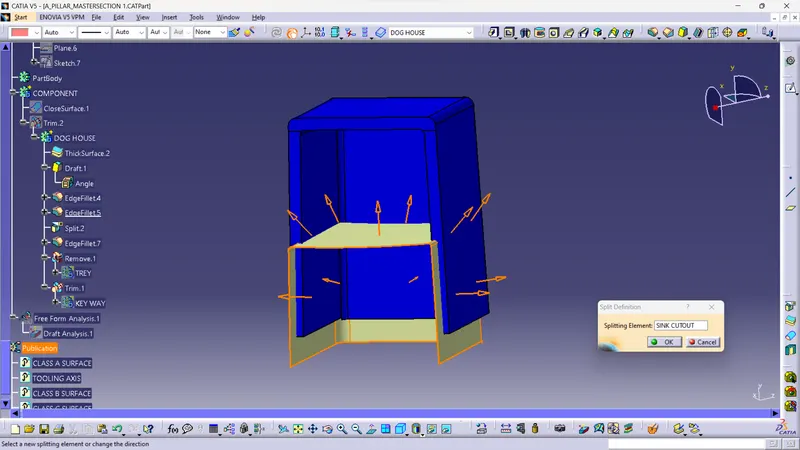
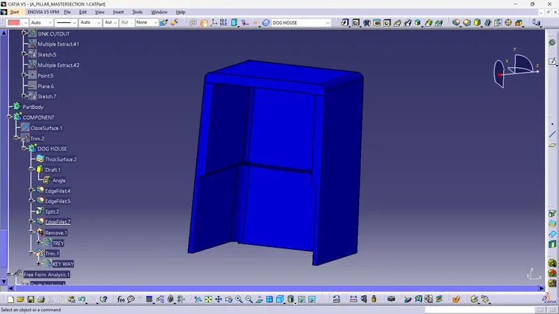
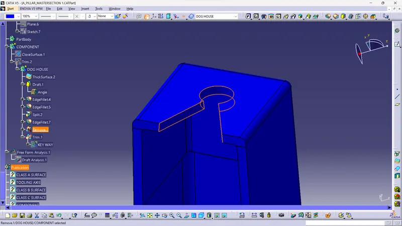
- create a key slot over the dog house top face for attatching another feature to dog houseand remove it using bolean operation.
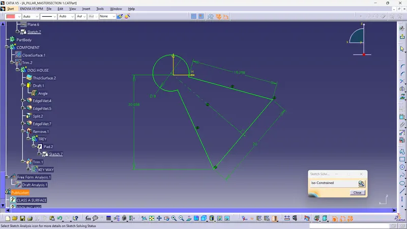
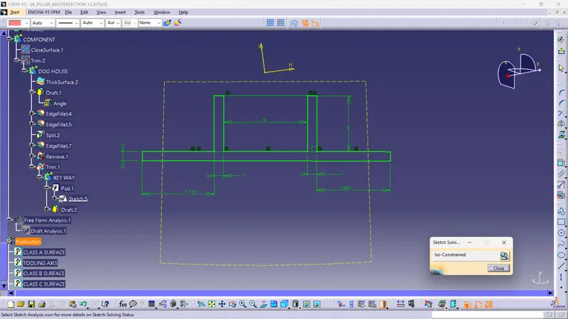
- finally creation of ribs inside the dog house feature.
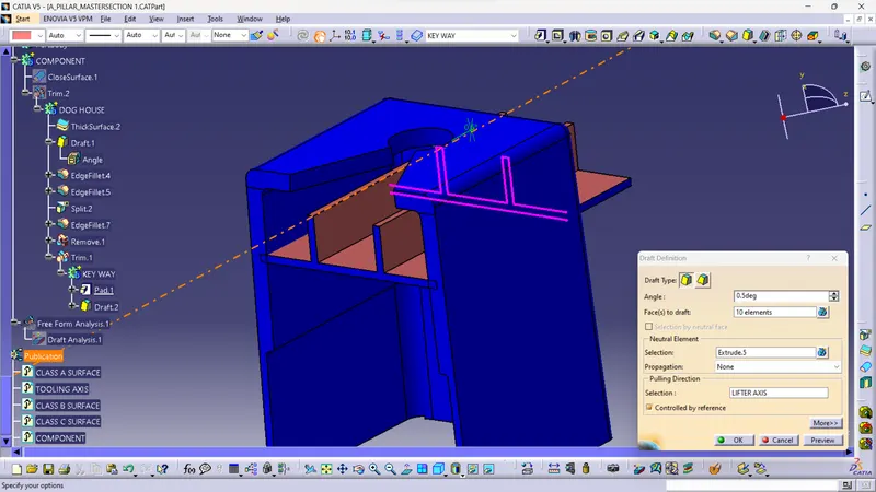
- also draft the ribs along with side core axis created for dog house with draft value of 0.5 degree.
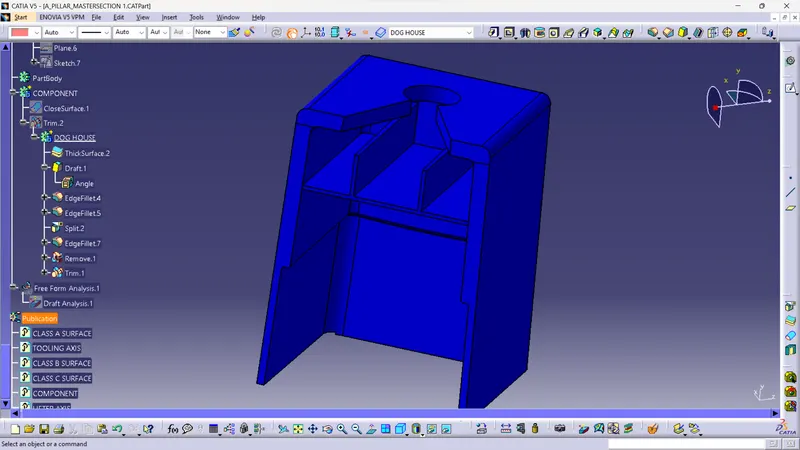
STEP 8- DRAFT ANALYSIS FOR FINAL COMPONENT.
- In this step we are going to check the draft of final component we created by considering all design rules is correct or not by repeating same procedure as we did for class A surface.
- But the diffrence is here we have to check it first for whole component w.r.t main Tooling axis and then for dog house seperately w.r.t. undercut axis.
- so first for draft analysis with main tooling axis
- select draft analysis cammand in the toolbar
- align the compass with the tooling axis and lock it
- select thr draft direction
- give input value of 3 degree and check whether the draft is correct or not.
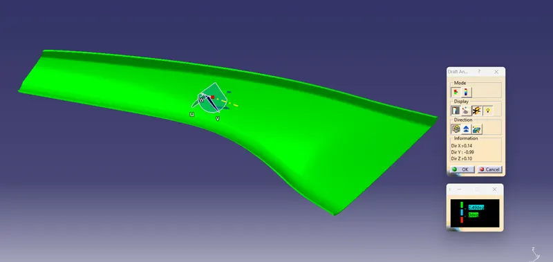
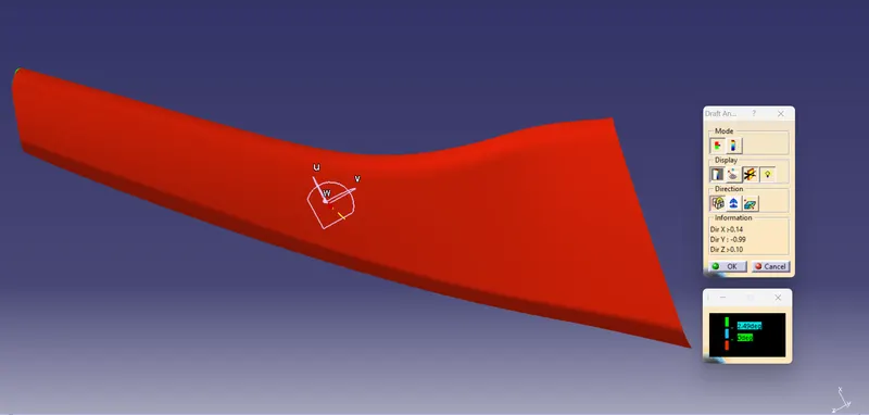
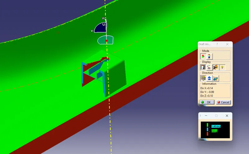
- now checking draft analysis for dog house with its attachment feature w.r.t. undercut axis.
- repeat same steps from aligning compass to final analysis except the draft value is 0.5 degree and undercut axis.
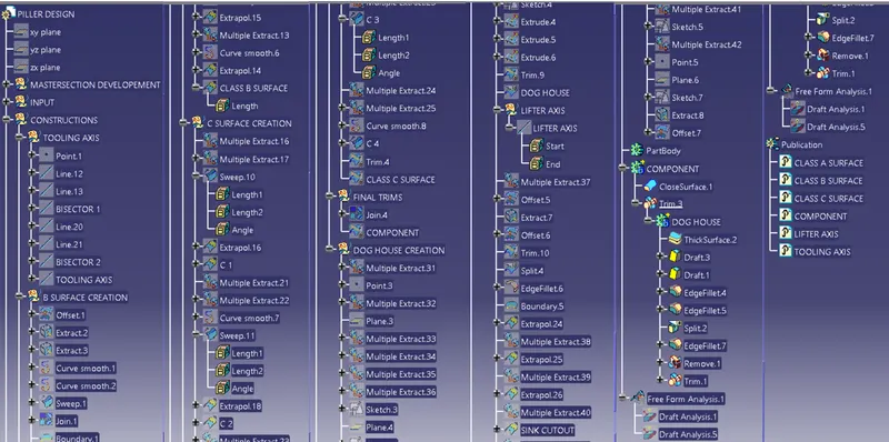
- Tree structure details.
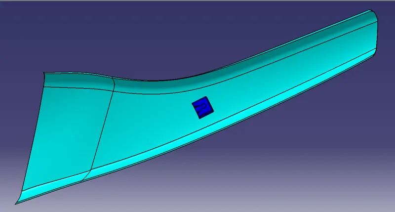
- Isometric view of component:
- CONCLUSION:
In this way i have sucessfully completed the project on A pillar Design with Master Section.